Program Design

Video Generation:
The code which draws the raster during the Timer 1 interrupt was borrowed from Professor Bruce Land's ECE-476 course website. In addition, the following portions were also borrowed from the same website:
- video_putchar() //draws a character on the screen
- video_puts() //draws a string of characters on the screen
- video_smallchar() //draws a small character on the screen
- video_putsmalls() //draws a string of small characters on the screen
- video_line() //draws a line on the screen
- video_pt() //draws a point on the screen
- video_set() //returns whether or not a point on the screen has been drawn
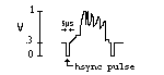
The purpose of the raster generation code is to generate a series of NTSC compatable voltage pulses which the television decodes and displays as an image. These pulses are generated from PORTD.6 in the following manner:
The signal on PORTD.6 traverses a DAC whose output is 0V when PORTD.6 is low, and 0.3V when PORTD.6 is high. The voltage drop is due to a 0.7V drop accross the diodes and a further drop accross the voltage divider.
The sync pulses are defined in the TIMER1 ISR. During execution of the ISR code, the CPU exits sleep mode and executes the timer1 ISR every 63.55us. If we start at LineCount =1, then first thing that occurs in the timer1 ISR is a horizontal sync pulse is generated by setting PORTD.6 = 0. Then some code gets executed (for 5us) and then PORTD.6 gets set 1. This effectively generates a 5us 0V pulse which is a horizontal sync pulse. This repeats 247 times, once for each line.
Then, a vertical sync pulse must be generated to signify the end of a frame. This is accomplished by setting PORTD.6 = 1 for 5us, and then PORTD.6 = 0 for the entire line (63.55us). This action results in 1 black line preceded by a 5us 0.3V pulse. Three such lines are generated from LineCount = 248 until LineCount = 251. Once LineCount = 251, then several "inverted" black lines are generated from LineCount=251 until LineCount=263. Each of these "inverted" lines are created by setting PORTD = b00000000 for 63.55us, followed by PORTD = b00100000 for 5us.
The horizontal sync pulses look like:
The vertical sync pulses each look like:
Brick Drawing:
The bricks are 7x2 pixels in size with 2 pixel spacing in both the x and y directions. We needed an algorithm that could draw many bricks in the fewest number of cycles in order to avoid screen flicker. To this end, we decided it would be best if the brick drawing algorithm were written in assembly language. We ultimately based our video_brick() algorithm off Professor Land's video_pt() method since it was very fast and could be easily modified to meet our needs.
Ball Trajectory:
The new reflection angle that the ball takes on as it bounces off the platform depends on where the ball strikes the platform. If the ball strikes the platform towards the platform's edge, the new ball trajectory will be more horizontal. If the ball strikes the platform exactly in its center, the new ball trajectory will be perfectly vertical. The trajectory after a reflection is calculated as follows:
dx = -(paddle_position-screenx)<<3;
dy = -(sqrt(speed - dx^2));
dx <<=3;
dy <<=3;
where dx and dy are the distances (in virtual space, not screen space) that the ball moves per frame in the x and y directions respectively.
Scoring:
For every brick destroyed, the player gets (10*difficulty level) points.
Every time a ball bounces off the platform, the player loses (1*difficulty level) points.
The player starts out with three lives, and upon completion of a level gains one additional free life.
Challenges Encountered:
We found several aspects of our project moderately challenging. First, screen flicker would occur as our intro splashscreen was displayed. We discovered that this problem was due to the fact that it took too many cycles to draw all the text to the screen in just one frame. We solved this problem by drawing one or two words on the screen each frame until all the text was displayed (7 frames later).
Second, building the standalone board ended up being more difficult that we anticipated because we spent a lot of time looking for bugs in the wrong places. For example, when our circuit's clock failed to produce a 16MHz sinusoid, we suspected that there must have been something (e.g. a short) wrong with our circuit's hardware. After testing many of its components including the capacitors, crystal, and all the wires, we ran out of ideas. The next day, we learned that the reason our circuit was not working was because we had failed to properly configure some project options in the compiler software.