| .:INTRODUCTION:. | ||||||||||||
|---|---|---|---|---|---|---|---|---|---|---|---|---|
| The DomMeter is a car performance meter that measures acceleration to compute values important to car enthusiasts. Specifically, the DomMeter calculates the 0-60mph time, 0-30mph time, 0-100mph time, quater mile, eighth mile time and braking time, the max acceleration during that interval, distance travelled in feet and max horse power generated (after drag, roll losses and drive train losses). This is all accomplished by sampling an analog accelerometer's output and performing computations on the value of acceleration. Integrating accerlation yields speed. Integrating speed yields distance. | ||||||||||||
| .:HIGH LEVEL DESIGN:. | ||||||||||||
|
We share a passion for performance cars. Our holy grail of a performance car is
a sub 5sec 0-60mph split. Additionally, Dominik works on the FSAE racecar here
at Cornell and desires a way to measure performance. There are commercial
products that do the same thing and even more, but this project gave us the
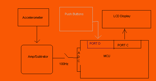
opportunity to have our own, at a cost of only our labor. There are basically 5 components to the DomMeter : The accelerometer, the lcd display, the analog amplifier, regulator, and the MCU.
Accelerometer:
We used a Kionix single axis accelerometer. The output at 0g's was already
centered at almost exactly 2.5 (2.48) V. There was a 0.4g swing in either
direction (-1g = 2.1V, 1g = 2.9V). The output was incredibly linear in that
range. Since we wanted maximum resolution from the ADC, we needed a way to get
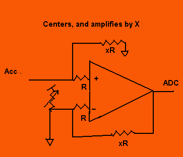
the output as close as possible between 0-5V instead of 2.1-2.9V. The analog amp was a subtractor/amplifier curcuit built using a 7111 opamp and several resistors. Basically the amp centered the output, and amplified that signal such that the resolution was 5x or 2.0V/g. LCD Display:The lcd display and pushdowns act as the user interface to the DomMeter. The combination allows the user to change settings, enter values and toggle modes. Regulator:MCU: Since we built at stand-alone board, there was significant work done to place the MCU and integrate the previously mentioned components. The MCU samples that accelerometer's output at 100Hz. |
||||||||||||
| .:PROGRAM DESIGN:. | ||||||||||||
|
The software multilevel state machine grew from initial code with one state.
As a result the code can seem dense and debugging became progressively more
difficult.
The program is divided into 5 modes: Calibrate, Get Weight, Type, Zero G Wait and Measure. All operation is controlled by timer1 interrupt. A 10msec time base was devised to provide the 100Hz sampling and sufficient time in between samples for computation. All three modes are run out of the interrupt service routine. The main loop only has code to capture the most accurate time in msec. The software integration is performed in the ISR. Calibrate: In the Calibrate mode, the mode entered to from Reset, the device seeks out 1) the max acceleration in the vertical direction and 2) the min. These are assigned the values of 1g and -1g respectively. The program takes note of the best possible values for these points over time by storing the max and min values respectively. Then the program can calculate 0g and the slope of the line. With these values, given any voltage the program can return the acceleration in [g] units. NOTE: When calibrating it is important to minimize any vertical movement because the resulting calibration values will be wrong. Get Weight: Since the program also measures peak horsepower, the user must enter the total weight in kg of the car and load (passengers, cargo, etc). Button 2 increases the weight by 5kg, while button 3 decreases the weight proportionally. These buttons were intentionally not debouced b/c the of the speed desired to approach the approximate weights and the inherent guessing/estimation on the user's part. Press Button 1 to enter the Measure mode. Type: In the Type mode you select the type of measurement you desire. You can choose from 0-60mph, 0-30, 0-100, braking time, quarter mile and eighth mile times. Zero G Wait: In this mode, the software is giving the user a chance to select among two options: 1) Manu[ual] start or 2) Auto[matic] start. A manual start begins the measuring as soon as button 1 is pressed. An automatic start begins the measuring once a reasonable threshold acceleration of 0.25g is reached. Since a car has tremendous initial acceleration inaccuracy due to Auto starts are negligable. The other useful feature of this state is the display of current acceleration. That allows the user to try and "level" the device prior to the run to get as accurate as possible. Measure: In measure mode, the LCD displays realtime values for g's, distance, and time (updated every 1/2 second). It continues to do so until the goal (Selected in Type mode) is reached. That this point the program enters a sub-mode of Measure, a display mode. By pressing button 2, you can toggle through displaying max hp, max accel, distance travelled and time in 10 msec increments. Pressing button 3 will take you back to Type mode for another run. |
||||||||||||
| .:HARDWARE DESIGN:. | ||||||||||||
|
We decided to build our own stand-alone board early on. This was quite
frustrating because no one was sure about the Mega32's settings off the
protoboard. After that hurdle, we proceeded to continue to build out all the
code around our functioning components. The wiring for the LCD is included in
the code listing. The LCD was connected to Port C. The Accelerometer went to
the operational amplifier circuit below (where x = 5). |
||||||||||||
| .:RESULTS:. | ||||||||||||
|
Performance: We tested our DomMeter both on the road and in the classroom. We are pleased to say that the meter provides very consistent and accurate results. Steady-state readings are within 1.5% error for distance, 0.5% velocity and an inherent ambiguity of 10msec in time. Readings of HP depend on drag, roll, drive train losses and other unaccountable factors. However, using error propagation, we can see that HP will be very accurate. Test Results are shown below. These tests were done in the lab because of the need for constant acceleration to verify experimental results.
Saftey: The device has no inherent saftey considerations. It is higly recommended that the dirver ask the passenger to help use the device. But even then, the device only needs attention before the launch. The passenger may help in recording more accurate times however by reducing the latency between when the measurement is started and the driver starts accelerating. Usability: The DomMeter is pretty usable. A novice user could be confused by the changing functions of each push button depending on the state of operation. There is a very short learning curve for this. |
||||||||||||
| .:IMPROVEMENTS:. | ||||||||||||
| We are considering making printed circuit boards (PCBs) for the DomMeter. In the future it would be nice to have another accelerometer in the vertical axis. This would allow us to compensate for tilting the DomMeter during runs. Another accelerometer in the y-axis would allow use to do skid pad/traction performance tests. Adding another axis would require vector math. | ||||||||||||
| .:CONCLUSION:. | ||||||||||||
| Our design was completely ours, based on our knowledge of the product we wanted and the features that existed on the market. We did not use anyone else's code. We don't believe that patent opportunities exist because of the existence of prior art. Also our project really didn't have much crossover with the IEEE code of conduct. All I can say I guess is that we didn't violate any of it... | ||||||||||||
| .:APPENDICES:. | ||||||||||||
| .:listing:. | ||||||||||||
| Code Listing | ||||||||||||
| .:schematics:. | ||||||||||||
This is the pin out of the MEGA32. Colored pins represent pins that were used
in the project.  PushButtons and OpAmp schematics
can be found in the Hardware Section. Dom will include more PushButtons and OpAmp schematics
can be found in the Hardware Section. Dom will include more
|
||||||||||||
| .:roles:. | ||||||||||||
|
Dominik: hardware configuration, component selection, circuit debugging Shyam: software configuration, ADC settings, OPAMP circuit, software debugging |
||||||||||||
| .:data sheets:. | ||||||||||||
|
||||||||||||
| .:parts:. | ||||||||||||
|
 The output of the opamp went to Port A, pin0- the input to the ADC channel we
were listening to in software. The push buttons are connected on Port D, pins
0-2, with the last button hardwired to the MCU's reset. The pushbuttons are
wired active low; we placed pullup resistors on the inputs to the push buttons.
The output of the opamp went to Port A, pin0- the input to the ADC channel we
were listening to in software. The push buttons are connected on Port D, pins
0-2, with the last button hardwired to the MCU's reset. The pushbuttons are
wired active low; we placed pullup resistors on the inputs to the push buttons. 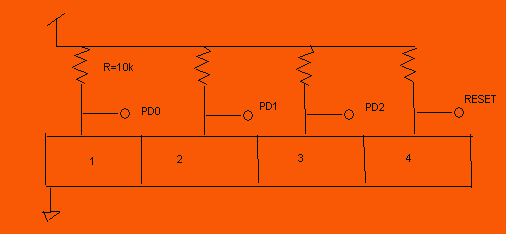 The accelerometer wiring was very straight foward. Vcc, Gnd and x-axis out . We also
have a conditioning circuit (regulator) to allow the DomMeter to be powered
from a car DC outlet.
The accelerometer wiring was very straight foward. Vcc, Gnd and x-axis out . We also
have a conditioning circuit (regulator) to allow the DomMeter to be powered
from a car DC outlet.