![]()
![]()
After cracking our heads for days about what to do, we were inspired by a couple
of projects done in the previous years that dealt with sound processing (such
as The Shredder). The high level design is summarized in the block diagram shown
below in figure 1.
Figure 1. Hardware block diagram.
The flow of the block diagram is rather straightforeward:
1) the audio input goes through an amplification and bias stage and then flows
through the ADC which is controlled via the SPI by the microcontroller.
2) the input is sampled at about 12,000 samples per second. We decided that
6 kHz and above will cover most of the frequency content of the expected audio
signal. 12 kHz made it sound better.
3) the microcontroller stores the input in an array and sends the output through
PORT D to the DAC while polling the buttons for user input
4) if no effects are turned on, the sampled output is sent straight out
5) if any of the effects are on, the microcontroller does the appropriate DSP
to the input and outputs theprocessed signal
6) the LCD will display which effects are on or off as well as the volume
The flow of the program
is summarized as follows:
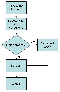
Figure 2. software block diagram
Our effects processor has the following functions:
| Function | Description |
| No effect | The microcontroller simply outputs the sampled waveform. |
| Volume control | button 6 will decrease the volume while button 7 increases it. Each press of the button will increment/decrement the volume by 1/8 of the waveform. |
| Reverb | button 5 will turn the reverb function on/off. Reverb is created by adding 25% of a previous signal and 12.5% of an even eariler signal to the current output. |
| Distortion | button 4 will turn the distortion function on/off. This effect is created by swapping the high and low bits of the sampled wave. |
| Bitflip | button 3 will turn the bitflip function on/off. This effect is done by zeroing every other bit of the output. |
| Slicer | button 2 turns the slicer function on/off. This effect is created by zeroing the output at regular intervals. |
All the digital signal processing was done in the microcontroller. The mathematics behind the various effects are detailed in the table below.
Function |
Mathematics |
Volume |
We first divided the input signal by 8(left shifting by 3) and then multiplied this input/8 signal by the volume number(1~16) to get the output. |
| Reverb | As mentioned above, we took 25% of a previous sample 900 samples before the current sample and 12.5% of a sample 1799 samples before and added it to the output. |
| Distortion | This was done by swapping the low and high nibbles of a byte. The signal was also forced to clip by setting the MSB to 0. |
| Bitflip | This was done by having a flag which was turned on every other byte and inverts every other bit of the byte. |
| Slicer | This was done using a flag which sets the output to 0 whenever it is turned on. at regular intervals. |