ECE 476 Final Project
Implementation of a (31, 16) BCH code on a
Microcontroller
Cezar Serban and Alexander Krol
Table of Contents:
Error
Correcting Codes and Finite Field Arithmetic: A Short Detour
Berlekamp’s binary BCH decoding Algorithm:
[4]
Implementing
a (31, 16) BCH code on the Mega32 microcontroller; Design Logic:
Patents
Copyrights and Trademarks:
Encoding
of the message stream:
Decoding
of the message stream:
Safety/security
considerations:
Standards,
Patents, and Intellectual Property Considerations:
Ethical
Considerations and the IEEE Code of Ethics:
Error correcting codes are used throughout digital communication systems today. Cell-phones, CD players, satellites, digital pagers and many other communication devices all use varying amounts of error control to achieve a certain degree of accuracy in transmitting information. The idea behind error control codes is very simple; one can insert some amount of controlled redundancy into an information sequence before transmitting it through an analog channel where it will be exposed to noise while on its way to a destination (the receiving end). The extra redundancy will help the receiver (to some degree) detect and possibly correct errors that occurred during transmission.
In our project we focused on implementing a (31, 16) triple error correcting binary BCH code. A BCH code is a type of block code; this means that information is split into blocks of a specified length and each block is separately encoded and decoded independently of the other blocks. In our code the number 31 represents the length of the code which is expressed in bits, and the number 16 represents the number of information bits per block. Thus our (31, 16) code has a redundancy of 31 – 16 = 15 bits per 31 bit block, which is a little under 50%. In general, the more redundant a code is, the smaller the data rate of the code is, that is the more total data one has to send per information bit.
In this project we designed and implemented our (31, 16) BCH code to run on the Atmel Mega32 microcontroller. We interfaced with the Hyperterm program on the computer in order to test our code on real data. When starting the project, we found that it was easier to first program and test our code at home on a C compiler and then later modify the program to work under the Cvavr embedded environment in lab.
High Level Design:
We were inspired to do a project on error control codes when thinking of the countless of times we handled, played with, and passed around burned CDs throughout our college careers. Making our own CD player seemed out of reach so we decided to design and implement an error correcting code that we could somehow run and test on the microcontroller. As a reach, we set the goal of interfacing whatever code we would choose with a wireless (802.11b) network card so that we could simulate a true wireless channel by sending data from the mcu to a nearby laptop. We were not able to reach this goal, since it took us most of the project allotted time just to program and test our code with Hyperterm using a software noise module.
Initially, we had to decide on the type of code that we could implement and turn into a full project. We knew that Hamming codes were very simple to do (besides they could only correct one error per block) and we also looked at some convolutional codes (which seemed to be too computationally intensive for the amount of error correction they provided). In the end we decided to try to implement a binary BCH code which we knew could correct a certain number of errors per block depending on the length and dimension of the code that we chose. Implementing a binary BCH code also seemed interesting because we knew their structure was closely related to the q-ary family of Reed-Solomon codes which are used in today’s CD players.
Before delving into the details of our specific BCH code, it is necessary to talk a little bit about the mathematics behind BCH codes.
Error Correcting Codes and Finite
Field Arithmetic: A Short Detour
The simplest possible error correcting code (and probably the worst in terms of redundancy) is the binary repetition code. For example in the length 3 binary repetition code, a 0 is mapped to the 000 code word and a 1 is mapped to the 111 code word. This code is highly redundant; it has a data rate of 1/3 meaning that only 1 in 3 bits is needed to perfectly reconstruct the message at the receiver if no errors in the channel occur. At the receiving end, decoding is performed by the majority rule, i.e. if two out of three bits are 0’s, the group of three bits get decoded to a zero. Using this code and assuming that the errors introduced by the channel are additive, one can easily see that this code can correct at most 1 error. That is if more than 1 error occurs in the code word, the decoder will incorrectly map the received data. For example if the original encoded message is 000111 and the channel flips the first two bits and the last one, the received data will be 110110. Hence if the receiver decodes by the majority rule, it will map the first three bits 110 to 111 (the wrong code word) and will also map the last three bits 110 to 111. In the first group the decoder made a mistake and mapped to the wrong code word because the number of errors that the channel added was 2, while in the last group of three bits the decoder again mapped 110 to 111 which happened to be correct since only one error occurred in the 3 bits.
We can measure the “Hamming distance” between two code words
as the number of coordinates in which the two code words differ. In the example
above, the Hamming distance of the 111
and 000 code words is 3 since they differ in all three coordinates. The minimum
distance of a block code is the minimum Hamming distance between all distinct
pairs of code words in the code. The example above suggests that the farther
apart (in minimum Hamming distance) code words are, the more errors a code can
correct. In general one notices that the length n binary repetition code has a
minimum Hamming distance of ![]() and can correct all
error patterns of
and can correct all
error patterns of ![]() weight, where the
weight of a code word or error pattern is defined as the number of nonzero
coordinates in the code word or error pattern.
weight, where the
weight of a code word or error pattern is defined as the number of nonzero
coordinates in the code word or error pattern.
BCH codes are a special type of linear cyclic block codes. A code is linear if and only if the set of code words forms a vector subspace over a finite field. For example, a binary linear code forms a vector subspace over GF(2), a field of 2 elements. The structure GF(2) is an example of a Galois or finite field. A Galois field is a mathematical structure that contains a finite number of elements upon which addition and multiplication is defined. A field F forms a commutative group under addition, with the additive identity element labeled as ‘0’. The field F without the ‘0’ element also forms a commutative group under multiplication, this time the multiplicative identity element is labeled ‘1’. A field F also satisfies the distributive property; that is a*(b + c) = a*b + a*c. Some important facts about Galois fields are as follows [1]:
- Every element in a Galois field has a unique inverse (this follows from the fact that a field F forms a commutative group under addition and multiplication).
- The size
of the Galois field (i.e. the number of elements in the field) uniquely
determines the field. The size of the Galois Field GF(
 ) for example, is elements.
- Galois
fields only exist for GF() where
 , where
  is a prime integer and
  is a positive integer.
- Every
finite field contains a primitive element; that is an element that when
multiplied by itself produces all of the other elements in the field. This
primitive element is sometimes called the generator of the field. Because
the result of a field operation on elements in a field must also be a
field element, it follows that in a field GF() the primitive element will cycle back to itself only
after multiplications.
- The
order of an element

 , is the smallest positive integer
 such that
  = 1. If is a primitive element, then from point 4 above it
follows that the order of is
= 1. If is a primitive element, then from point 4 above it
follows that the order of is  .
.
- The
field GF() where is prime, is formed from the integers {0, 1, 2,…., -1) under modulo addition and multiplication. For example, the binary
field GF(2) is formed from integers in the set {0, 1}. Addition modulo p
is as follows: 0+0 = 0, 0 + 1 = 1 + 0 = 1, but 1 + 1 = 0 (mod p).
Multiplication is as usual.
A linear block code satisfies the property that the linear
combination of any subset of code words is also a code word (this makes sense
since the set of code words forms a vector subspace, implying closure under
field operations). Linear codes have a specified block length and dimension;
for example an (n, k) linear code over GF(2) has length n and dimension k. The
length of a code is just the number of coordinates in each code word of the
code. The dimension k of the code is the dimension of the vector space of the
linear code. Thus the number valid code words of a (n, k) linear code over
GF(2) is ![]() . Another way of seeing this is to think of a message of
length k being encoded into a code word of length n (n > k ensures that
redundancy is added to the message). If the message is in binary (i.e. over the
field GF(2)), and each message produces a unique code word, we can see that the
total number of valid code words is exactly
. Another way of seeing this is to think of a message of
length k being encoded into a code word of length n (n > k ensures that
redundancy is added to the message). If the message is in binary (i.e. over the
field GF(2)), and each message produces a unique code word, we can see that the
total number of valid code words is exactly ![]() , corresponding to
, corresponding to ![]() possible messages. The code words of the code form a subspace
over the vector space of all n-vectors (that is over all
possible messages. The code words of the code form a subspace
over the vector space of all n-vectors (that is over all ![]() possible n-tuples).
possible n-tuples).
Not only is a BCH code linear, but it is also cyclic. In a
cyclic code, for every code word ![]()
![]() ,
, ![]() is also a code word.
Thus all n shifts of
is also a code word.
Thus all n shifts of ![]() are also code words. To understand cyclic codes and therefore
BCH codes we need to think of code words as code polynomials. For example the
code polynomial for
are also code words. To understand cyclic codes and therefore
BCH codes we need to think of code words as code polynomials. For example the
code polynomial for ![]() would be a polynomial of degree n-1 coordinates of
would be a polynomial of degree n-1 coordinates of ![]() , i.e.
, i.e. ![]() . It is very important to notice that code words are uniquely
mapped to code polynomials and vice versa. This one-to-one mapping allows us to
look at the properties of cyclic codes.
. It is very important to notice that code words are uniquely
mapped to code polynomials and vice versa. This one-to-one mapping allows us to
look at the properties of cyclic codes.
For any q-ary (n, k) linear cyclic code C the following statements are true. (These facts will allow us to understand how a message can be encoded by a BCH code).
- Within
the code polynomials of C there
exists a unique monic(i.e that has leading coefficient equal to 1)
polynomial
 with minimal degree r = n – k < n. is called the generator polynomial of C.
 - Every
code polynomial
 can be expressed uniquely as
  where is the generator polynomial of the code C and
  is a polynomial of degree less than
  (Later we will
see that will be associated with a message that we want to
encode).
(Later we will
see that will be associated with a message that we want to
encode). - The
generator polynomial of the code C
is a factor of
 with coefficients in the field
 (i.e. q-ary coefficients).
Encoding:
To encode a ![]() symbol message block
symbol message block ![]() we first associate it
with a code polynomial
we first associate it
with a code polynomial ![]() We then multiply
We then multiply ![]() by
by ![]() (where n is the length
of the cyclic code) and divide the result by a generator polynomial,
(where n is the length
of the cyclic code) and divide the result by a generator polynomial, ![]() to obtain a remainder
to obtain a remainder![]() . (Since the degree of
. (Since the degree of ![]() is r < n, the higher the degree is, the more redundancy
the code has, but more redundancy is needed to correct more errors per block
length).
is r < n, the higher the degree is, the more redundancy
the code has, but more redundancy is needed to correct more errors per block
length).
Polynomial division by ![]() is equivalent to
saying
is equivalent to
saying ![]() where
where ![]() is the quotient polynomial and
is the quotient polynomial and ![]() is the remainder polynomial with degree(
is the remainder polynomial with degree(![]() ) < degree(
) < degree(![]() ) =
) = ![]() . This is equivalent to
. This is equivalent to ![]() But since
But since ![]() is a multiple of
is a multiple of ![]() it must be a code
polynomial. Hence the encoding procedure
it must be a code
polynomial. Hence the encoding procedure ![]() =
= ![]() produces a valid code polynomial.
produces a valid code polynomial.
How do we choose a generator polynomial![]() ? The BCH bound states that in order to construct a binary
t-error correcting BCH code, one must first pick a field
? The BCH bound states that in order to construct a binary
t-error correcting BCH code, one must first pick a field ![]() that contains a primitive element
that contains a primitive element ![]() (i.e has order
(i.e has order ![]()
![]() -1). Therefore
-1). Therefore![]() must satisfy the equation
must satisfy the equation ![]() (i.e be a root of unity). The BCH bound also states that
(i.e be a root of unity). The BCH bound also states that ![]() must have as zeroes
must have as zeroes ![]() consecutive powers of
consecutive powers of ![]() . Hence if we look at the complete factorization of
. Hence if we look at the complete factorization of ![]() into primitive
polynomials, we will be able to find a generator polynomial that contains
into primitive
polynomials, we will be able to find a generator polynomial that contains ![]() consecutive roots of
consecutive roots of ![]() .
.
Decoding:
When errors are added to the code word by the channel, we
can write the received polynomial as the sum of the encoded code polynomial and
an error polynomial. That is ![]() where
where ![]() is encoded polynomial and
is encoded polynomial and ![]() is the error introduced by the channel. If we evaluate
is the error introduced by the channel. If we evaluate ![]() where
where ![]() ranges over the
ranges over the ![]() consecutive powers of
consecutive powers of ![]() , we know that
, we know that ![]() by the BCH bound,
therefore
by the BCH bound,
therefore ![]() =
=![]() which will give the location of the errors. All computations
of the syndromes
which will give the location of the errors. All computations
of the syndromes ![]() ,
, ![]() , are computed in
, are computed in ![]() . In order to evaluate the syndromes we must be able to add
two different powers of
. In order to evaluate the syndromes we must be able to add
two different powers of ![]() over
over ![]() . The easiest way to do this is to construct a look-up table
of all powers of
. The easiest way to do this is to construct a look-up table
of all powers of ![]() , up to
, up to ![]() In order to do this we
first find a primitive polynomial
In order to do this we
first find a primitive polynomial ![]() of degree
of degree ![]() and let
and let ![]() be a root; this
implies that
be a root; this
implies that ![]() We can now express all powers of
We can now express all powers of ![]() from
from ![]() to
to ![]() in terms of lower powers of
in terms of lower powers of ![]() up to
up to ![]()
A syndrome polynomial can be formed from the ![]() syndrome results. The polynomial has all the syndromes as
coefficients and is as follows:
syndrome results. The polynomial has all the syndromes as
coefficients and is as follows: ![]()
We can now run Berlekamp’s Algorithm which attempts to
iteratively find an error locator polynomial solution ![]() to the following:
to the following:
![]() where k ranges from 1
to
where k ranges from 1
to ![]()
Berlekamp’s binary BCH decoding Algorithm: [4]
Step 1: Set up the following initial conditions: k = 0, ![]()
![]()
Step 2: Have ![]() be the coefficient of
be the coefficient of ![]() in the product
in the product ![]() .
.
Step 3: Calculate ![]()
![]()
Step 4: Compute ![]() =
=
Step 5: Set ![]() If
If ![]() then iterate back to
step 2.
then iterate back to
step 2.
Step 6: Determine the roots of ![]()
![]() . If the roots are distinct and lie in the
. If the roots are distinct and lie in the
right field, then flip the bits corresponding to the error locations. Otherwise declare a decoding failure.
Berlekamp’s algorithm allows one to correct errors that occur in a BCH code. If there are more errors than the code can correct, the algorithm will return a decoding failure.
Implementing a (31, 16) BCH code
on the Mega32 microcontroller; Design Logic:
After this (rather lengthy) mathematical discussion on
algebraic block codes, we can now describe some of the reasons and logic behind
our code selection. After we decided to implement a BCH type of code, we had to
figure out the number of errors per block that we wanted the code to correct.
As we were not sure how fast the code would run on the microcontroller, we
decided to use a length 31 = ![]() code (we found that this code could potentially correct up to
7 errors). The next smallest length we could use for a binary BCH code was 15 =
(
code (we found that this code could potentially correct up to
7 errors). The next smallest length we could use for a binary BCH code was 15 =
(![]() ) and this could only correct up to 3 errors at a lowly data
rate of 1/3 (i.e. 1 bit of information sent for every 3 bits transmitted).
Looking at the cyclotomic cosets of GF(32) with respect to the binary field,
GF(2), we noticed that
) and this could only correct up to 3 errors at a lowly data
rate of 1/3 (i.e. 1 bit of information sent for every 3 bits transmitted).
Looking at the cyclotomic cosets of GF(32) with respect to the binary field,
GF(2), we noticed that ![]() perfectly factored
into 6 minimal polynomials each of degree 5 and one of degree 1. Since the
generator polynomial could be any of the factors of
perfectly factored
into 6 minimal polynomials each of degree 5 and one of degree 1. Since the
generator polynomial could be any of the factors of ![]() , we noticed that the number of errors the length 31 code
could correct had values between 1-7 (not including 4 or 6) [1]. Upon looking
at the dimension of the message, we conveniently found a (31, 16) code that
could correct up to 3 errors per block; this was nice because two characters
(equivalent to 16 bits) could be encoded upon every iteration without having to
add/subtract extra bits to the message. A length 31 code could also be easily
stored as an unsigned long data structure; this allows for efficient software
implementation. The redundancy of this code is a little under 50% (15 bits/31
bit block), while the redundancy of the (31, 11) 5-error correcting code (the
next allowable code which has a degree 20 generator polynomial) is much worse
(20 bits/31 bit block). Not knowing how fast the code would run on the
microcontroller until we programmed it, we decided to be conservative and use
the less redundant, more convenient, but only 3 error correcting (31, 16) BCH
code.
, we noticed that the number of errors the length 31 code
could correct had values between 1-7 (not including 4 or 6) [1]. Upon looking
at the dimension of the message, we conveniently found a (31, 16) code that
could correct up to 3 errors per block; this was nice because two characters
(equivalent to 16 bits) could be encoded upon every iteration without having to
add/subtract extra bits to the message. A length 31 code could also be easily
stored as an unsigned long data structure; this allows for efficient software
implementation. The redundancy of this code is a little under 50% (15 bits/31
bit block), while the redundancy of the (31, 11) 5-error correcting code (the
next allowable code which has a degree 20 generator polynomial) is much worse
(20 bits/31 bit block). Not knowing how fast the code would run on the
microcontroller until we programmed it, we decided to be conservative and use
the less redundant, more convenient, but only 3 error correcting (31, 16) BCH
code.
Hardware/Software Tradeoffs:
Besides the Mega32 microcontroller and the STK500, we did not use special hardware circuits to implement our BCH code; instead we designed and implemented them in C. The downside to this is that the code might not run as efficiently in software, but on the other hand, software allows different ways to implement the code and even combine it with other codes to achieve a desired level of error correction. If very high data rates are required for an application (hundreds or even thousands of megabits per second), a hardware implementation is not only a good idea, but is often the only way of implementing codes [1]. The application speed requirement could severely limit the complexity of the hardware circuits to the point where only simple elements can be used (special purpose circuits such as switches, shift registers, and finite field adder and multiplier circuits).
Error Control Standards:
Some standards in error correction systems exist, such as the Red Book Standard developed for audio CDs. CD players use CIRC coding(Cross-Interleaved Reed Solomon Coding) which can correct burst errors of up to 3500 bits (2.5mm) and can interpolate error bursts of up to 12,000 bits(8.5mm) [2]. In general different applications use different types of error control codes due to different design requirements (low power, high data rate, bursty channel, etc). Our BCH code follows the standard error correction capability of a block code based on the prior specification that it must be able to correct 3 errors per block length.
Patents Copyrights and
Trademarks:
We used Berlekamp’s Algorithm to efficiently decode messages while implementing our BCH code. Although Berlekamp’s algorithm is probably patented, it is widely accepted as a standard in the decoding of BCH and Reed Solomon codes.
Program/Hardware Design:
Our C program can be split into two main parts:
Encoding of the message stream:
Initially a pre-specified message (character array) is stored in the flash memory of the microcontroller. All encoding/decoding is done on this message. (If the user wants to change the message, he must store a new message to flash and recompile the modified c program. For long messages, this implementation avoids using a large buffer that would be needed if the message is to be changed through Hyperterm)
The function EncoderBCH grabs a 16 bit message (2 characters) and systematically encodes it into a 31 bit structure (which is stored as a 32 bit unsigned long). As mathematically described above, the 16 bit message is encoded by left shifting by the degree of the generator polynomial (of degree 31-16 = 15) and adding to this result a remainder. The remainder is found by dividing the shifted result by the generator polynomial. All addition, multiplication, and division is done over the binary finite field, GF(2). (As 1 + 1 = 0 in this field, the Xor function is extremely handy in implementing finite field arithmetic).
Upon encoding the message, an artificial noise module is added to the 31 bit code word. The noise error can be toggled on or off through Hyperterm and a user can add a varying amount of error when testing the BCH code. The noise module is implemented using the C function rand. In Hyperterm the user specifies the maximum number of bit errors that will be added to a 31 bit block. Thus on every block iteration, the noise module randomly chooses a number of errors ranging from 0 to the user specified maximum. Based on this number, the error module again randomly chooses the locations of the bit errors in the block. At each location the encoded bit is flipped and the encoded message plus error is sent to the decoder for processing. Through Hyperterm, the user can choose to print to the screen any intermediate encoding steps, such as the original message, the encoded message bit array, the encoded message with errors, the number and location of errors in a block.
Decoding of the message stream:
The function DecoderBCH grabs the encoded message array and calculates 6
syndrome values by evaluating the array at 6 different powers of alpha (a
primitive element in the field GF(32)). A lookup table (and a reverse lookup
table) are stored in flash for this purpose. Each lookup table is an array of
32 characters; each character value corresponds to a different power of alpha.
The lookup tables have been hard coded into flash due to their memory expense
(this is not as critical in GF(32), but for a bigger field such as GF(128) or
GF(256) it will be absolutely necessary) and the values are taken from the
field structure of GF(32) using the degree 5 primitive polynomial ![]() (if any other degree 5
primitive polynomial would have been used, the numbers would have been
different, but the field structure would still have been the same; there are in
fact five other choices for degree 5 polynomials, see appendix of [1] ).
(if any other degree 5
primitive polynomial would have been used, the numbers would have been
different, but the field structure would still have been the same; there are in
fact five other choices for degree 5 polynomials, see appendix of [1] ).
The next step in the decoding process takes the syndromes and forms a syndrome polynomial (implemented as an array of characters) proceeding to Berlekamp’s Algorithm for decoding. This is the most computationally intensive part of the decoding process because a couple of different functions that operate on GF(32) elements are called in the algorithm. The algorithm finds an error locator polynomial by iterating through the syndrome polynomial; the upside is that the number of iterations (and hence the complexity of the algorithm) linearly increases with the number of errors the code can correct. For a relatively small number of errors per block (3 for our code) the algorithm only needs to iterate 6 times before it stops.
Berlekamp’s algorithm produces an error locator polynomial which is tested to find the location of the roots. If the roots are not distinct, and/or do not lie in the right field, a decoding failure occurs and is printed to the Hyperterm screen. The current block is left alone, the message block with errors is displayed and encoding of the next block starts. Otherwise (if the number of errors is smaller or equal to 3) the roots of the error locator polynomial uniquely identify the error locations in the message array and the corresponding bits are flipped and corrected. The corrected message is displayed in Hyperterm and the next message block is processed.
There were a few parts (mainly specific functions) of our program that were tricky to implement. The division function over a binary field was written, but was not initially well tested for certain cases (i.e. signed versus unsigned chars); this brought up errors at a later programming stage and made it difficult to isolate the location of the bug. When writing the code, we realized two important things: First, regardless of how simple certain code looks, it needs to be tested as soon as it’s written. Many times we became tempted to move on to more interesting things without thoroughly testing seemingly flawless code. A lot of bugs came up later to haunt us for not paying close attention to innocent looking code. Second, we realized that programming at home on a C compiler and transferring our code to the Cvavr environment in lab are two completely different experiences; the Cvavr compiler is a lot more annoying and painful to deal with, sometimes refusing to do things that were easily accepted by the C compiler at home. (We even stumbled on a possible bug in one math library functions in Cvavr that cost us a couple of hours to debug).
All software written for this project is entirely our own, and we believe that the program is well commented and documented so that in the future another group could easily run and/or make modifications to it. In particular, a future group could take our BCH code and combine it with another type; maybe a convolutional code or a different type of block code, such as a Reed-Solomon code and compare the different performance levels. A more challenging idea would be for a group to use our code and interface with a wireless device so that information could be sent across a true noisy environment. There are other possibilities here; our software is general enough that it could easily be modified to implement other BCH codes in higher fields. The field lookup tables would have to be changed, and the code length and dimension would also change, yet a lot of the code would remain the same for higher fields and/or higher error correction capability.
Results:
Speed of Execution:
Our program encodes and decodes a typical message array (1 or 2 sentences) within a couple seconds. When all the printing functions are enabled in Hyperterm, the program displays intermediate information to the screen, and as a result displaying the decoded message to the screen may take a couple of extra seconds due to the extra information that is printed. Although we have tried to write good code, we believe that more efficient implementations exist out there. As a future project, it may be instructive to possibly rewrite all or parts of our code to increase the execution time on the microcontroller.
During the demo session we measured the baud rate of our encoder and decoder. We did this by removing all nonessential code (i.e. all of the functions that print to screen in Hyperterm). In order to measure the baud rate for every data block, we flipped PINB.0 – hence once complete cycle is completed for every 2*32 = 64 bits. Using the oscilloscope, we found approximate frequency values of 53.6Hz for the encoder and 43.2 Hz for the decoder. Multiplying these values by 64 results in approximately 3600bps for the encoder and 2800bps for the decoder. Therefore our encoder/decoder system could easily be used for a standard baud rate of 2400bps
Accuracy:
Our BCH code is 100% accurate when no noise is introduced in the channel. Every message is successfully encoded and decoded and the BER (bit error rate is zero) because the noise on the microcontroller does not affect any of the variables in memory. When we introduce noise (up to 3 errors per 31 bit block) the code again successfully corrects the entire message. With random errors between 0-3 occurring per block, we calculated an initial BER of approximately 5.5%. Since the code can correct up to 3 errors, the measured BER in the end is 0.
For higher artificial noise (for example up to 4 errors occurring per 31 bit block), the initial calculated BER is around 7.5% and the BER after error correction occurs drops to approximately 3.5%, a 4% improvement. For 5 errors/block we found an initial BER of around 9.5% and a corrected BER of approximately 6.5%, a 3% improvement in error correction.
Safety/security considerations:
As our project is almost all software oriented, physical safety was not much of a concern for us. The more interesting topic deals with the security of our design as compared to the security features of other real life designs. In a world where all kind of critical information needs to be sent across a communication channel, data protection is a real concern. Our BCH code guarantees error correction up to a certain degree (i.e. three errors per block), but it quickly fails if the amount of error surpasses that amount. Therefore in security critical applications, our BCH code should only be used if the amount of error introduced by the channel is known to be limited to the error correcting capabilities of the code. If for example a remote bank account transfer of a large sum is initiated, it may be well worth the effort to add extra measures of error protection to the transfer mechanism even if probability of error is tiny (for example a bit flip could turn a very significant 1 into an insignificant 0 or vice versa and if the decoder doesn’t detect that an error occurred, the result could be catastrophic for the client or the bank).
We did not have any problems with interference from other people’s design. Had we been able to implement our reach goal of wireless communication across two mcu’s or between a laptop and an mcu, we could have potentially had interference introduced from other projects in the lab.
Our project is very easy to use and test using Hyperterm. A menu function which clearly highlights all program choices is displayed to the user upon initialization of the program. A user can trace out the relevant steps of the encoding/decoding process by printing out all information to the screen. The user can toggle noise on or off and can add varying amounts of error to the message. The user can also compare the original message with the decoded message directly, or by displaying the bit error rates of the encoded/decoded message.
We were pleased with the results of our project. Initially we had some doubts about whether our code will execute encoding/decoding quickly on the microcontroller; if the mcu will have enough memory to operate; whether we would be able to smoothly interface with Hyperterm. As we were unable to find any past projects of error control code implementations on the microcontroller, we hoped that everything would work in the end. In the beginning it felt a little unsettling to commit to a particular code
(a (31, 16) BCH code) because we knew we would have to essentially start all over if something went wrong and the microcontroller couldn’t handle the required computation.
Upon looking back, we realize that given more time, we could add more codes and/or complexity to the program and it probably wouldn’t affect the microcontroller execution speed too much. We would have to be careful and more efficient about the amount of extra memory we would use; 2K of SRAM can go pretty fast when implementing multiple error control codes.
Standards, Patents, and Intellectual
Property Considerations:
As mentioned above, our design procedure is based on standard techniques for the software encoding and decoding of BCH codes. In particular we must owe our thanks to Elwyn Berlekamp for his efficient (but painful to implement) decoding algorithm (which he published sometime in the 1960s). His algorithm has set the standard for the decoding of Reed Solomon and BCH codes. All of our code is entirely our own, but we don’t believe any of it contains new ideas that would make it eligible for a patent.
Ethical Considerations and the IEEE Code of
Ethics:
Throughout our project, we have abided by the IEEE code of ethics. Some examples follow:
Point 1. to accept
responsibility in making engineering decisions consistent with the safety,
health and welfare of the public, and to disclose promptly factors that might
endanger the public or the environment;
We have accepted responsibility for making our engineering
decisions in a manner that is safe, healthy, and contributes to the welfare of
the public. We take pride in knowing that our project will be a useful and safe
learning experience for others someday.
Point 3. To be honest
and realistic in stating claims or estimates based on available data.
From the start of our project, we have attempted to make a realistic project plan and to try to stick to it in our objectives. To the best of our ability we have tried to verify the accuracy of all data generated by our project. Furthermore, we attempted to give credit and reference all claims that are not our own.
Point 7. To seek,
accept, and offer honest criticism of technical work, to acknowledge and
correct errors, and to credit properly the contributions of others.
We have appreciated all the help we received on this project
from the TA’s, our peers, and Professor Land. We have attempted to give credit
to all people and sources that have helped us complete this project.
Point 9. To avoid
injuring others, their property, reputation, or employment by false and
malicious action.
Being a software project, it is impossible for our project to directly injure anybody. We have been respectful to our peers in the lab, from the early half-empty weeks of the lab, to the overcrowded last minute sessions.
Point 10. To assist
colleagues and co-workers in their professional development and to support them
in following this code of ethics.
We have tried to be helpful and assist other students whenever they needed help, whether in class or in the lab. In return we have also benefited from the help of other peers and made a few friends in the process.
Click Here for the commented Source Code.
Below are some pictures of our project:
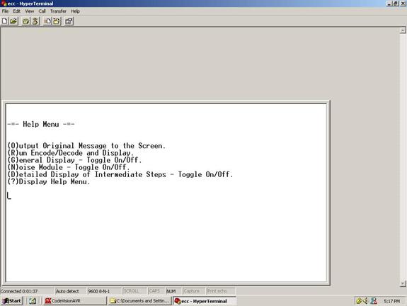
Figure 1: Picture showing the main menu of our project
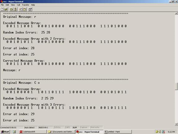
Figure 2: The original message, the error locations, and the corrected message
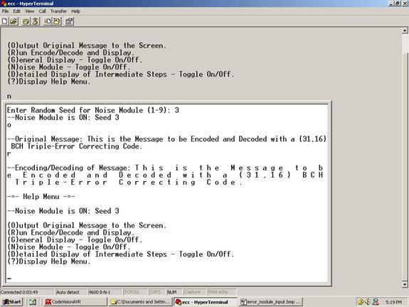
Figure 3: Original Message along with the Decoded Message
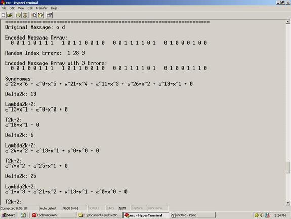
Figure 4: Detailed display showing specifics of the decoding process.
We had no hardware costs in our project other than the Atmel Mega32. Hence the total cost came out to $8 dollars.
Alexander Krol implemented most of the encoder functions and finite field arithmetic functions. Cezar Serban designed the noise module and wrote most of the decoding functions. We both worked on implementing and debugging Berlekamp’s decoding Algorithm and both wrote the final project report.
[1]. S. Lin and D.J.
Costello, Jr. Error Control Coding:
Fundamentals and Applications,
[2]. Hanley, Stan. “Reed Solomon Codes and CD Encoding.”
http://web.usna.navy.mil/~wdj/reed-sol.htm
[3]. “Algebraic Decoding” http://math.berkeley.edu/~berlek/alg.html.
[4]. E.R Berlekamp, Algebraic
Coding Theory,
[5]. F. J. MacWilliams and N.J.A. Sloane, The Theory of Error Correcting Codes,
[6].
[7] Atmel Mega32 DataSheet
http://instruct1.cit.cornell.edu/courses/ee476/AtmelStuff/full32.pdf