Introduction High Level Design Hardware Design Software Design
Conclusion & Results Code Appendix State Machine
“to build a navigating robot that can move from one place to another avoiding obstacles placed in its way.”
We decided to do this project due to our keen interest in the robotics. We were also looking for a project that involved a perfect mix of hardware and software complexity. This project enabled us to use new hardware such as sensors, stepper motors and their integration in big projects.
The robot was made from a metal sheet as its base. This navigating robot is basically a car, which is operated by two stepper motors and an omni directional wheel at the other end to move it in any direction. IR distance sensors were used to identify the obstacles placed in its way. Gears were used for the wheels, which gave us a mechanical advantage of speeding up the robot. We also made a grid from a board, which is used as a track on which robot moves.

Navigating a robot without any obstacle was our first goal. To do that first of our problems was to measure the distance covered by the robot. Due to wheel slippage it is not possible to calculate the distance with respect to the number of motor rotations. We then decided to make a grid with black lines on it, which will be detected by phototransistors. This approach simplified moving robot from one location to another.
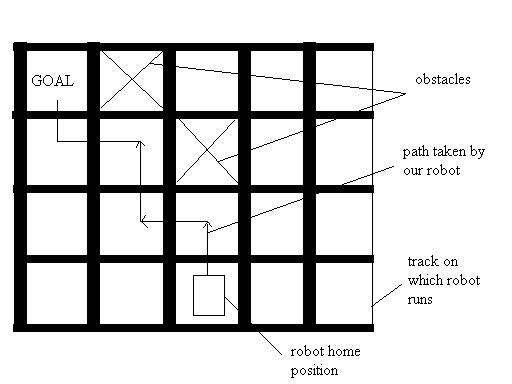
Figure1: typical navigating robot scenario
One more problems that we came across was robot losing its alignment and moving waywardly in random direction. This happens because practically it is not possible for two different motors to move by same angular distance. We discovered that same phototransistors could be used to solve this problem. Whenever one of the wheels crosses the black line, it stops and allows other wheel to rotate so that it can match with this. This solved the problem and robot realigns itself at every black line moving in desired direction.
After achieving robot movement without obstacles we decided to integrate obstacle avoidance. We use SHARP proximity distance sensor to detect obstacles. Though we ordered analog distance sensor, which generates voltage depending on the distance between sensor and obstacle, we used it in digital mode by amplifying the output. We do not really need to know the distance but the presence of obstacle in the next grid position. So whenever robot detects an obstacle it takes left or right turn depending upon the final destination.
A basic hardware schematic is as shown in the figure below.
(Please note that the picture of the chip shown below is not the same as the Atmel Mega32 it’s a general Atmel microprocessor schematic from OrCAD – all details of the stand alone MCU have been ommited because of )
The LO voltage source is a regulated 5V input.
The HI Voltage source is a
unregulated 12-15V input for the

The hardware essentially consists of:
Electrical Parts
- MCU – Atmel Mega32
- Stepper Motors (2 in Number) - the motors used here are the mono-polar type.
- Op – Amps (3in Number) – for amplification of the sensor signal.
- (2 in Number) – for the detection of the lines
- Sharp GP2D12(1 in Number) – for the detection of obstacles and the distance
- Misc – Resistors, capacitors, 16MHz oscillator, piezoelectric speaker, wires etc.
Mechanical Parts:
- 20cm x 13cm Steel Plate – to serve as the chassis of the robot
- .5 cm Shaft to mount the gears and also the rear omni wheel
- 2 2cm gears to serve as the wheels of the robot
- Sheet Metal to mount the GP2D32 and the motors
- 2 inch aluminum standoffs and locks to hold the board.
- Misc – screws, bolts, hot glue , duct tape etc.
Mechanical Assembly and Design:
Mechanical fabrication to create something that moves around was a challenge that had to be dealt with considerable effort.
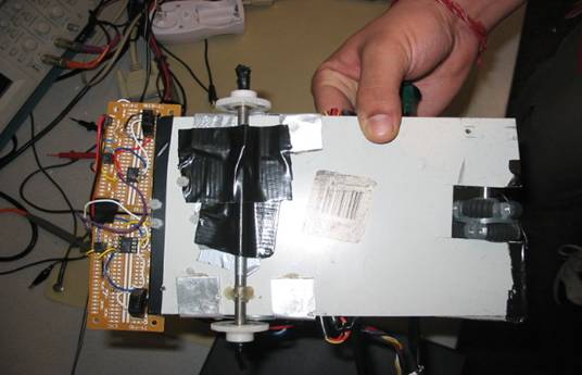
A steel plate of 20x13 cm was taken and a notch of about 2.5x3 cm was cut on one of the sides to accommodate the omni-wheel.
Next shafts were hack-sawed and secured in place with the help of hot glue and some tape with the gears and wheels in place.
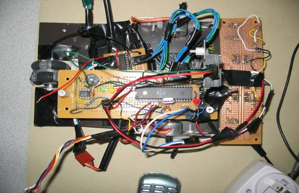
The design is shown below with the bottom view and the side view.
Apart from the design shown above, two holes were drilled in the front of the robot and three random holes to mount our circuit board using aluminum standoffs.
Electrical Design:
The electric design was more of a challenge simply because we had a lot of things being interfaced with the MCU at once.
To this end we followed a very systematic approach towards our project and interfaced every thing one at a time. Providing final software touches right at the end.
The schedule and the order of design is as shown:
|
Friday |
2nd |
stand alone board |
|
Monday |
5th |
stepper motor |
|
Friday |
9th |
AI routing algo |
|
Monday |
12th |
basic tests on sensors |
|
Wednesday |
14th |
test on sensors+functions for sensors |
|
Friday |
16th |
mechanical fabrication |
|
Monday |
19th |
integration(grid and other) |
|
Wednesday |
21st |
integration(mech and s/w) |
|
Friday |
23rd |
debug |
|
Monday |
26th |
debug |
|
Wednesday |
28th |
report |
|
Friday |
30th |
report |
Most of the electrical work was debugging of the board and the sensors.
The sensors that we have used are:
1. Sharp GP2D12 – This range finder is one of the most commonly used in autonomous robotics applications for hobbyists and also in academic research. The reasons for this are essentially its low price, its compact (~40x14x13mm) and lightweight package. The GP2D12 is based on the triangulation principle with a collimated infrared LED for the emitting element and a PSD (Position Sensing Device) which constitutes the receiver.
|
|
|
|
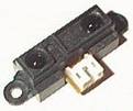
The main motivation for this choice is that the digital version is almost twice slower than the GP2D12 (update period about 75ms against 40ms for the analog version). Table 1 gives a brief overview of the GP2D12 specifications.
|
Range: |
|
10 to 80cm |
|
Update frequency / period: |
|
25Hz / 40ms |
|
Direction of the measured distance: |
|
Very directional, due to the IR LED |
|
Max admissible angle on flat surface: |
|
> 40° |
|
Power supply voltage: |
|
4.5 to 5.5V |
|
Noise on the analog output: |
|
< 200mV |
|
Mean consumption: |
|
35mA |
|
Peak consumption: |
|
about 200mA |
|
|
||
The Sharp GP2D12 was used primarily for distance sensing. Output of the sensor was fed into an OPAMP with a gain of 1.5 – this gives a high level TTL signal for a distance of about 7 inches which is what we need for obstacle detection.
2. Fairchild QRB1114 - consists of a infrared emitting diode and an NPN silicon phototransistor mounted side by side on a converting optical axis in a black plastic housing. The phototransistor responds to radiation from the emitting diode only when a reflective object passes within its field of view. The area of the optimum response approximates a circle of .200 inch in diameter.

Two QRB1114 sensors were used to detect black and white parts of the track and was the sense to navigate and align the robot. Their operation was critical because they compensated for the lack of mechanical performance of the robot. The output from the Sensor was fed to an OPAMP with a gain of 2 – this gave a TTL high for white and a low for black, making the sensing of the lines possible.
This gives a good outline of all the hardware used in our Robot.
Designing software for this project was completely new experience. We did not use any of the components in previous projects so interfacing them with software was difficult. To achieve the software goals we moved in steps along with the hardware we built.
Software design can be broken into four sections as stepper motor control, line-sensing unit, obstacle detection and avoidance, path calculation.
Stepper motor control was very straightforward. We started with a small program generating pulses in required sequence. After successful execution of this program we moved motors in such a way that robot can move forward, backward and can turn left, right. To move forward both motors move in forward direction whereas to move backward both motors move in backward direction. To take turns we need to turn motors in opposite directions.
For line sensing unit we used to phototransistors, which were placed near front wheels. They can sense black line and its detection are used to keep track of the distance. Whenever robot identifies a black line, it increments distance in X or Y direction depending on its current orientation. We keep track of the orientation on every turn we take. Robot can have plusX, minusX, plusY and minusY as its orientation. This orientation is initialized in plusX direction. One more important use of these sensors is to realign robot. Due to slippage of wheels due to traction robot loses its alignment during the course of navigation. Whenever single sensor sense a black line, it turns robot in such a way that robot realigns itself. This step is very important because if we lose our alignment all our distance measurements will no longer be valid with respect to the starting position.
We used distance sensor to find the obstacles placed in robot’s way. Whenever state machine is executed we check for an obstacle. If there is an obstacle it takes turn depending upon the final destination and orients itself. We also keep track of previously identified obstacles as history so that they can be used if robot comes to the same position again. In this case we take it to some random place and start ultimate navigation.
Path calculation employs simple method of moving in short goals. If no obstacle is present, robot moves in X direction till it matches with X co-ordinate of the destination and then it takes left or right turn depending upon the Y co-ordinate of the destination. Now in presence of obstacles first it will try to go along the normal path and when obstacle is identified it takes turn and tries to make to the co-ordinate of the destination in current orientation.
Constraints: To handle L-shaped obstacles robot keeps track of obstacles that came in its way in previous attempts. We used only two history flags in this project due to small grid, so whenever more than obstacles are placed next to each other in robot’s path it oscillates between those. Number of history flags can be increased easily depending upon the size of the grid and user interest.
/*----------------------------------------------------------
NAVIGATING ROBOT
Spring 2004: Fianl Project ECE476
Presented by:
Pranay Ahlawat (pa63)
Abhijeet Dhanapune (ad284)
---------------------------------------------------------*/
#include<Mega32.h>
#include<delay.h>
//define directions
#define straight 0
#define back 1
#define left 2
#define right 3
#define stop 4
#define stepleft 5
#define stepright 6
//the turning var
#define leftturnvar 300
#define rightturnvar 300
#define forwardvar 400
#define t1 3
//define sensors
#define LS PIND.5 //top left sensor
#define RS PIND.4 // top right sensor
#define obstacle PINB.3 //distance sensor
//define varriables
char time=t1;
char a=0;
unsigned char x=1+8;
unsigned char stepL;
unsigned char stepR;
unsigned char dir;
//hardcode the final destinations for the sensors
#define ultimatex 3
#define ultimatey -2
char xfinal=3;
char yfinal=-2;
char interx=0;
char intery=0;
char temp1x=0; //for one of the history
char temp1y=0;
char temp2x=0; //for the other history
char temp2y=0;
//define directions as numbers - this will be used as the orientation refference
#define plusx 1
#define minusx 2
#define plusy 3
#define minusy 4
//varriables to keep track of the current location
char currentx=0;
char currenty=0;
//define initial varriables
char orientation=1; //the list of orientation is given in the#difines
above
char temp;
int count,i;
//define the functions
void initialize(void);
char backward(char x);
char forward(char x);
void move (void);
void ai(void);
void rightturn(void);
void leftturn(void);
unsigned char obstacleflag=0;
void sound(void);
void force(int);
//ISR 0 definition
interrupt [TIM0_COMP] intaaaa(void)
{
--time;
}
//initialization of the data direction bits and also the timer constants
void initialize(void)
{
DDRC = 0xff; // MSB for L and LSB for R
DDRD = 0x00; // higher byte debug with led and lower byte for line sensors
DDRB=0x00;
DDRA = 0xff;//00000010;
TCCR0= 0b00001011;
OCR0=249;
TIMSK=0b00000010;
#asm
sei
#endasm
PORTD.4 = 1;
PORTD.5 = 1;
PORTD.6 = 1;
for(i=0;i<50;i++)
sound();
//for motor
dir = back;
count = 0;
}
//force function - force moves in a particular direction
void force(int a)
{
for(i=0;i<a;i++)
{
move();
delay_ms(2);
}
}
//begin the main routine
void main(void)
{
initialize();
//Intellifent determination of the final coordiantes
//interx=char(ultimatex/2);
//intery=char(ultimatey/2);
interx=1;
intery=1;
while(1)
{
if (time==0)
{
time=t1;
//realign
PORTA.6=0;
//realign
if (!LS) PORTA.5=1;
else PORTA.5=0;
if (!RS)PORTA.4=1;
else PORTA.4=0;
if (obstacle)
{
sound();
switch(orientation)
{
case(plusx):
{
if (yfinal>currenty) {xfinal=currentx;yfinal=currenty+1;leftturn();orientation=plusy;}
else if(yfinal<currenty)
{xfinal=currentx;yfinal=currenty-1;rightturn();orientation=minusy;}
else {xfinal=interx;yfinal=intery;rightturn();rightturn();orientation=minusx;}
break;
}
case(minusx):
{
if (yfinal<currenty) {xfinal=currentx;yfinal=currenty-1;leftturn();orientation=minusy;}
else if(yfinal>currenty)
{xfinal=currentx;yfinal=currenty+1;rightturn();orientation=plusy;}
else {xfinal=interx;yfinal=intery;rightturn();rightturn();orientation=plusx;}
break;
}
case(plusy):
{
if (xfinal<currentx) {yfinal=currenty;xfinal=currentx-1;leftturn();orientation=minusx;}
else if (xfinal>currentx)
{yfinal=currenty;xfinal=currentx+1;rightturn();orientation=plusx;}
else {xfinal=interx;yfinal=intery;rightturn();rightturn();orientation=minusy;}
break;
}
case(minusy):
{
if (xfinal>currentx) {yfinal=currenty;xfinal=currentx+1;leftturn();orientation=plusx;}
else if (xfinal<currentx){yfinal=currenty;xfinal=currentx-1;rightturn();orientation=minusx;}
else {xfinal=interx;yfinal=intery;rightturn();rightturn();orientation=plusy;}
break;
}
}
if ((temp2x==currentx && temp2y==currenty) || (temp2x==currentx
&& temp2y==currenty)) //if its any one of
//the previous two encountered then goto the middle
position and then refind the way
{xfinal=interx;yfinal=intery;}
if (obstacle) {xfinal=interx;yfinal=intery;} //if you find another obstacle then move
//to the middle position - this is again to avoid an L shaped obstacle
//update the history of the robot
temp1x=temp2x;
temp1y=temp2y;
temp2x=currentx;
temp2y=currenty;
}
if(!LS) //if the left sensor is detected then turn left to allign
{
dir=left;
}
if(!RS) //if the right sensor is detected then take a right to allign the robot
{
dir=right;
}
if (LS && RS) // if none then keep moving straight
{
dir = straight;
}
if (!LS && ! RS) //if the sensors become alligned
then move straight and call the ai
{
dir=straight;
PORTA.6=1;
force(forwardvar);
ai();
}
move();
}
}
}
void move (void) //move the robot depending on the action requested
{
if (dir == stepleft)
{
stepL=backward(stepL);
}
if (dir == stepright)
{
stepR=backward(stepR);
}
if(dir == straight)
{
stepR = forward(stepR);
stepL = backward(stepL);
}
if(dir == left)
{
stepR = backward(stepR);
stepL = backward(stepL);
}
if(dir == right)
{
stepR = forward(stepR);
stepL = forward(stepL);
}
if(dir == back)
{
stepR = backward(stepR);
stepL = forward(stepL);
}
if (dir == stop)
{
stepR=0;
stepL=0;
}
PORTC = (stepL <<4)|stepR;
}
char backward(char x) //for a wheel to go left
{
switch(x)
{
case (8+1):
{
x=4+8;
break;
}
case 1+2:
{
x=8+1;
break;
}
case (2+4) :
{
x=1+2;
break;
}
case 4+8 :
{
x=2+4;
break;
}
default:x=8+1;
}
return x;
}
char forward(char x) //for a wheel to go forward
{
switch(x)
{
case (8+1):
{
x=1+2;
break;
}
case 1+2:
{
x=2+4;
break;
}
case (2+4) :
{
x=4+8;
break;
}
case 4+8 :
{
x=8+1;
break;
}
default: x=8+1;
}
return x;
}
void sound()
{
PORTA.3=1;
for (i=0;i<100;i++);
PORTA.3=0;
}
void ai(void)
{
// char xdiff; //define varaibles
that will be the differece in the final and the
current position
//char ydiff;
switch (orientation) //update the value of the current coordiantes
because the robot just crossed the line
{
case (plusx):
{
currentx++;
break;
}
case (minusx):
{
currentx--;
break;
}
case (plusy):
{
currenty++;
break;
}
case (minusy):
{
currenty--;
break;
}
}
//if there is an obstacle then change the finalx and finaly coordinates to make the thing go to the left block
switch(orientation)
{
case (plusx):
{
if (currentx>xfinal)
//if you have overpassed the point and the direction
is plusx take a u turn
{
rightturn();
rightturn();
orientation=minusx;
}
if (currentx==xfinal) //if
you have covered the x coordinate ..
{
if (yfinal>currenty)
//and you are away from y - take a left
{
leftturn();
orientation=plusy;
}
if (yfinal<currenty)
//otherwise take a right to hone in on the target
{
rightturn();
orientation=minusy;
}
}
break;
}
case (minusx): //if the orintation
is -x
{
if (currentx<xfinal)
//take a uturn if you are opposite to where you have
to go
{
rightturn();
rightturn();
orientation=plusx;
}
if (currentx==xfinal)
{
if (yfinal>currenty)
//if you have achieved x then take a right if you have to treverse
positive y
{
rightturn();
orientation=plusy;
}
if (yfinal<currenty)
//take a left turn if you have to go to a y that is negative with respect to position
{
leftturn();
orientation=minusy;
}
}
break;
}
case (plusy) : //if the orientation is plusy
{
if (yfinal<currenty)
//take a uturn if you are going in the opposite
direction
{
rightturn();
rightturn();
orientation=minusy;
}
if (currenty==yfinal) //if
the y direction has been acheieved then
{
if (currentx<xfinal)
//if you have to go to x take a right
{
rightturn();
orientation=plusx;
}
if (currentx>xfinal)
//otherwise if you have a negative distance take a left
{
leftturn();
orientation=minusx;
}
}
break;
}
case (minusy): // if you are going in the negative y
direction
{
if (yfinal>currenty)
//if you are travelling away from the target take a u
turn
{
rightturn();
rightturn();
orientation=plusy;
}
if (currenty==yfinal) //
otherwise if y has been achieved
{
if (currentx<xfinal)
{
leftturn(); //and you are away from x in + - take a
left
orientation=plusx;
}
if (currentx>xfinal)
{
rightturn(); //otherwise take a right
orientation=minusx;
}
}
break;
}
}
if((orientation!=plusx) && (orientation!=minusy) && (orientation!=minusx)
&& (orientation!=plusy))
while(1)
{
sound();
}
if (currentx==xfinal
&& currenty==yfinal)
// if you have achieved the temporary target
{
xfinal=ultimatex; //change
the target to the final destination
yfinal=ultimatey;
}
if (currentx==ultimatex
&& currenty==ultimatey)
// if you have achieved the final destination
{
while(1) //stop and make a sound
{
sound();
}
}
}
void rightturn(void) //to turn right
{
dir=right;
force(rightturnvar);
dir=straight;
}
void leftturn(void) //to tuen
left
{
dir=left;
force(leftturnvar);
dir=straight;
}
Results & Conclusion
We think we achieved what we set out to achieve and we are also very satisfied with the way our robot runs and navigates. The robot works according to the specification that we have set for it and in most cases – lands at the destination with the shortest path.
There are a few things that could be improved:
- AI
could be made more robust
- Mechanical
Fabrication needs a lot of work
- Intelligent
Surface error algorithms could be implemented
- More
sensors could be included
All in all it was a very satisfying project for us and we enjoyed thoroughly.
We would like to thank Prof. Land and the TAs for 476 for all the help rendered. We would also like to acknowledge the team Intellibot from where we took the ideas for driving stepper motors and robot design.
Throughout the project we have adhered to the IEEE code of ethics and we also declare that:
1. We accept responsibility in making engineering decisions consistent with the safety, health and welfare of the public. Our project objective does not contradict this goal.
2. Our work was consistent with the spirit of improving the understanding of technology. This project has been a great learning experience. It was immensely enjoyable with lots of intellectual satisfaction. We understood our limitations in Analog Design, and appreciated the fact that people have designed and commercialised very useful analog circuits.
3. We will strive to maintain and improve our technical competence and to undertake technological tasks for others only if qualified by training or experience, or after full disclosure of pertinent limitations. Our project decision described in the Summary section proves that we did not venture into a field in which we lacked expertise, namely Kalman filtering. We accepted our limitations in Analog Design, and used commercial sensors.
4. We will seek, accept, and offer honest criticism of technical work, acknowledge and correct errors, and credit properly the contributions of others. We sought the advice of Professor Land and our class-mats while encountering different problems, while offering our own opinion to fellow students in their undertakings.
5. We will treat fairly all persons regardless of such factors as race, religion, gender, disability, age, or national origin. Our project will definitely excite a person regardless of his caste, colour, or creed.
For any further information the authors of this paper can be contacted:
Pranay Ahlawat pa63@cornell.edu
Abhijeet Dhanapune ad284@cornell.edu
Parts Details
|
Part Description |
Part Number |
Quantity |
Total Cost |
|
Micro controller |
1 |
0(sample) |
|
|
Circuit Board |
|
1 |
3 |
|
Stepper Motor |
|
2 |
4 |
|
Optical Sensors |
2 |
2.6 |
|
|
Distance Sensors |
1 |
11 |
|
|
Big Boards |
|
3 |
7.5 |
|
Small Boards |
|
4 |
3.2 |
Total Cost: $32