Hardware Design
Now to the real meat and potatoes of the project. The actual building of the scanner. We salvaged the wood from a crate behind Thurston and much of the metal came from ceiling tile anchors found behind Phillips. The mouse sensor were collected from old mice that were no longer useful, and other parts of the mice were incorporated into the axles for movement. The threaded rods were cut by hand which ended up taking about 30 minutes and a lot of brute strength.
Glue and screws were used throughout the project to hold all different types of materials together, and copper wire was utilized to hold the gears and axles in place. A part of a pen and some straws were utilized in creating the holder for the sensor. Of all the task required to create the physical portion of the scanner it was the gluing that was the most frustrating and time consuming. Certain types of glue would not bond two types of plastic together and super glue is totally useless since it doesn't bond fast enough to be used to bond a metal screw to plastic.
The scanner is pretty close to square, off by a little under 1/8" which is decent considering the inaccuracy in every cut we made. For the most part there was a very general idea of what the scanner was to look like which was highly dependent on what materials we could actually come upon to use.
If someone would like to build a scanner of similar attributes as this one feel free to contact Andy Hocker aeh28@cornell.edu for more info, it would be to tedious and also too confusing to explain on a web page. But for a little more clarity we have included some photos of the scanner with some of the important areas focused on.
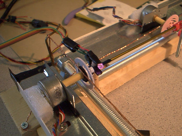
One can see the infrared sensor (mouse sensor which is glowing purple) and the incredibly fine detail of the threaded rods and gears as they move over the metallic surface, which happens to be one of the ceiling tile pieces.
The actual electrical hardware was rather easy to build. The mouse sensors were the hardest to setup since we had no idea what the pin layout was. But after blowing one device out we were able to establish the layout and then made the decision that if we used an op amp for comparison we could convert the output to TTL logic level which would make using these sensors in our project easy and also would make it incredibly fast to determine if one of the axles had returned to its starting position. To compare we had to fool around with voltage dividers until we found a happy combination that would activate the sensor in an acceptable manner. A really cool trick that helped us determine if our infrared diodes were on was that the diodes glowed green to white in my camera cell phone, actually any CCD, which made it much easier to setup the corresponding sensor. As can be seen from the above picture the sensor is basically held together with superglue, a portion of a straw, some electrical tape, and some hot glue.
The sensor for light and dark detection was even easier to build. After a little searching about how the device worked we came to establish a setup that would magnify the output of the sensor by a factor two which seemed to yield a very good range of white being near 4.5 Volts and black at around 0.9Volts. We then could use AREF as the comparison for the ADC for establishing the color of the pixel.
The schematics in the schematics section are a good reference for building the above circuits.
From here we first made all of our circuits on protoboards to test and then converted the whole setup to solder-boards.
The Hardware design was a lot of hard work and a lot of trial and errors, even with the scanner in a very good working state we still occasionally have some mechanical glitches and errors and are constantly fixing and mending the mechanical pieces of the project. We have a much deeper respect for mechanical engineers and all the headache that goes with creating a reliable design.