High Level Design
Many will probably wonder where this crazy idea and design for a scanner came from. Well it developed in Andy's mind about 6 years ago, when he owned a Lego Mindstorms and read on some random website about how some user had developed a scanner. After only see a very small dark image of what the scanner looked like he made a valiant attempt to create his own scanner with his extensive collection of Legos. Unfortunately not enough Legos were to be found and the design and the idea were left to collect dust. Till one day..
Then came along the 476 ECE Final Project where the idea jumped back to life but this time it would be designed out of scrap parts and every aspect built or written and tested thoroughly.
The way in which the scanner actually goes about scanning is an incredibly essential and very well throughout method. In a traditional scanner the actual scanning sensor is a fix width wide and as a result only requires one fixed pass of the image (i.e. moving vertically across the image) to scan in the entire image. Now maybe if we had really searched around and begged for samples we might have received one of these wonderful scanning sensors, but instead we decided to opt for the $1.29 solution of a Phototransistor reflective object sensor (QRB114). This meant that the sensor would be reading one pixel at a time which implies that our design would have to move both in the vertical and horizontal direction. The upside of this design is that we could, at least in theory, scan any imaginable size image (actually the area scan-able is approx. 12in by 9.4in). Unfortunately there are a few large downsides to this method; It is very slow and all this back and forth movement requires rather precise control of exact position of the scanner head.
We couldn't really do much about the slowness other than try to create faster ways to scan, like the zig-zag method as we call it, where you take sensor data as the sensor head moves in the positive direction, then when it hits the maximum x distance you move the y distance down one and take sensor data as the sensor moves back to the starting x position.
To maintain precise position of the sensor head we implemented a rather clever design, at least we think it is clever and probably the coolest part of the whole project, the treaded rods and gears connected to stepper motors. The threaded rods are nothing but incredibly long screws, which can also be visualized as a very large gear that has had the teeth on the circumference laid out in a straight line. Therefore the actual gears can move with great precision on the threaded rods and we can maintain a more discrete way of representing distance in the x and y direction. To create this discrete positioning also required the use of stepper motors. The stepper motors used in this lab where some remaining ones from years before, with little documentation but luckily due to The Postage Meter Project (sp 2002), we were able to hook them up and after some rudimentary work determine that the angle was 15 degrees which made the half step 7.5.
We made the determination that we would do all the stepping of the motors in software which at the time of writing this might have been a slight mistake considering the motors after hours in operation are occasionally acting rather odd.
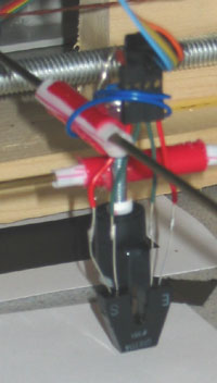
With the x y position figured out we had to hook the sensor onto the crossing of the x and y axles (which are just coat hangers), this turned out to be a major headache which required a couple different gluing attempts and a lot of jerry-rigged wire setups to hold the sensor in place. (See image below showing a blue wire holding sensor in place)
The final piece of the design was the use of cannibalized mice position sensors. We used these sensors to define the starting (home position) for both the x and y direction. We realized that we need some specific location to start scanning from especially given the fact that every time we reset up the scanner the gears and the axles had shifted way out of whack.
Below is a simple diagram as to how we mapped out how the software would function in this lab.
The intent was to create a simple user interface with buttons that allowed the user to select a resolution of scanning and a possible mode.
Types of tradeoffs involved:
We could have implemented the stepper motor control in hardware which would have required more logic which might have implied another solder board (I think 3 is enough) and may have save some of the painful determination of which brush to run next depending on if the motor is now going forward or backward.
There really isn't much that we built in hardware that we could implement in software, except maybe make the mouse sensor outputs feed straight into the ADC, but this would have slowed down the scanner even more and we think the op-amp setup we created is more superior since it converts the analog signal to a TTL logic level.