Program Design
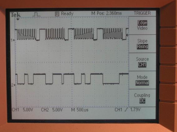
We spent much time getting the PS/2 communication protocol working. Our MCU is able to generate data and clock signals for it to be recognized by the computer boot up sequence. After the BIOS boot up, Windows (or other operating systems) is able to detect our mouse and show it on the screen. We are also able to send movement byte packets to the computer that represents movement and clicking of the mouse. Upon boot up sequence, we also were able to identify ourselves as a Microsoft scrolling mouse and were able to send a four-byte movement packet including the scrolling data byte. The Microsoft scrolling mouse send movement packets of four bytes, whereas the normal PS/2 mouse sends movement packets of three bytes. We followed closely to the PS/2 communication protocal by following the information given on Adam Chapweske's page. We also used Joseph Weaver and Rob Buels's host emulator to test our mouse software design. We used the AVR protoboard with the 90s8515 chip for the host emulator. We also intercepted signal from a real Mircosoft's scrolling mouse to follow the delay between bytes and packets exactly. We used a state machine for transmitting and receiving mouse packets. There are four states in the state machine. First is an IDLE state. In the IDLE state the outputs will float high if the mouse is not sending anything. If the mouse has anything to send, it will go to the BUSY state. Depending on weather the mouse is sending packets to the host or receiving the packets from the host, it will set corresponding output flags 'transmitting' or 'receiving'. The PS/2 communication is two-way, and the host can inhibit mouse's activity by pulling the clock signal to low for more than 100 microseconds. Since the clock period of the mouse is 80 microsends, the mouse can check if the host has been trying to inhibit communication by checking if the mouse is outputting high clock but is actually reading a low from the clock because the host is pulling it low. Our clock frequency is 12.5 kHz, which is acceptable for a PS/2 protocol which requires frequency from 10 kHz to 16 kHz. After the mouse sees the host inhibits for more than 100 microseconds, it the state machine will transition into the INHIBIT state, stop all transmission and float both clock and data to 1. Note however, if the host inhibits transmission before the mouse finishes sending a byte (bit 10 of the byte), the mouse will prepare to resend that byte again whenever possible. The host can request to send information to the mouse by pulling the data line low after he pulls the clock line low for more than 100 microseconds. This makes the state machine to transition into the REQUEST state. By the next clock cycle the state machine will transition into BUSY state with output 'receiving' equals to 1. When the host pull the data line low this is a signal for start bit for the mouse, and the mouse should start generate clock signals by first making clock to high. The host will then send the 11 bit data when the clock is low, and the data becomes valid when the clock is high and then the mouse can check the data when the clock is high. After receiving the stop bit from the host the mouse will send an ACK bit to the host when the clock is high and the host will read that ACK bit when the clock is low.Please refer to Adam Chapweske's page for more information. It is important to note that in a digital design with clock signals such as the PS/2 mouse we need to be careful about the states and the signals and should avoid hazards. This means that all state machines should be driven by the same clock and we should avoid clock skews. Failure to do so will result in unpredictable behavior for both the state machine and the signals. In our design found out that we should only change the state and the output when timer 1 interrupts for the signals to be synchronous. We spent much time trying to debug our digital design and signals and were finally able to get our mouse recognized by the BIOS and Windows. PS/2 Mouse Port Mouse Motion Report Formats: Microsoft IntelliMouse Explorer pointing devices with IntelliEye optical tracking technology support three different PS/2-compatible packet formats, depending upon the following operational modes: �E Standard mode Standard Packet Format: Microsoft "3-Button" IntelliMouse Z-Mode Report Format A Microsoft IntelliMouse 3-Button Z-mode motion report consists of a 4-byte packet defined as shown below:
Symbol definition: Xov, Yov: Overflow. Indicates more than 9 bits of movement detected. X8-X0 or Y8-Y0 should be set to maximum magnitude in the appropriate direction. X8-X0: 9-bit signed twos complement integer that presents the relative displacement of the device in the X direction since the last data transmission. A positive value indicates motion to the right; a negative value indicates motion to the left. Y8-Y0: Same as X8-X0. A positive value indicates device motion
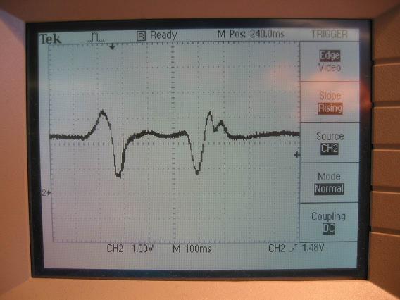
upward; a negative value indicates motion downward. Zs: Z-wheel twos complement sign bit. Zse: Z-wheel sign extension bits. Always the same as Z3. Used for compatibility with old drivers. MS Extension: Many Microsoft mice use 8-bit internal counters and sign extend the values into X8 and Y8. Microsoft mice do not use the Yov or Xov bits, and they set them to 0. Besides the PS/2 standard of byte transmission, there is also PS/2 mouse specific commands that we implemented. They can be found in Adam Chapweske's page. For example, a host can request for send and then sends an 0xFF to the mouse, which is a reset command to reset the mouse. The mouse should respond all the host commands with an ACK byte (0xFA), plus any additional data that the host requires. Note that the delay between the 0xFF command and the ACK byte should be 700 microseconds, while the delay between other commands and the ACK byte should be about 200 microseconds. The host does not expect to receive the ACK from the mouse too soon because the mouse is resetting. Also, after the mouse sends the ACK byte when the mouse received an 0xFF command, it should wait for about 350 miliseconds, then sends to the host an 0xAA byte initilization) and an 0x00 (device ID). If the 350 miliseconds wait was too short then the host may generate an error packet (0xFE) and the BIOS or Windows boot up sequence might fail to recongnize the mouse. We reused Luke Hejnar and Sean Leventhal's queuePut and queueGet functions for implementating a queue to send the bytes. We also recoded Joseph Weaver and Rob Buels's processcommand function and changed their assembly code to c code for our mega 32 chip. Other than the software to drive the PS/2 signal, we also have software to convert the ADC reading to mouse movements. We put the first acclerometer in our mouse horizontally, and we take the tilt reading of X and Y as compared to a calibarated flat value when we first acquire when the mouse resets. Then we set the packet bits and store that packet into the queue. For scrolling, we use another accelerometer that is stacked perpendicularly to the first accelerometer to measure the vertical acceleration and movement. We detect scrolling up by an swift upward than download movement, and we detect scrolling down by an swift downward than upward movement. To correctly interpret this, we needed another state machine, first by checking if the z value is around zero, then it checks for a maximum and minimum value followed by the zero. If the mouse is scrolling up, the sequence should be zero-minimum-maximum-zero. If the mouse is scrolling down, the sequence should be zero-maximum-minimum-zero. After some tweaking we were successfully able to implement scrolling.
|