Do you love to smash? Have a need to crash? But are low on cash?
We introduce to you a cost effective Mini RC car to satisfy all your demolition derby needs. The basic concept behind the Demolition Derby RC Car is a radio control car with a MCU to detect physical collisions. These physical collisions are then calculated into “performance penalties” depending on how hard and where the collision occurred. Get hit hard too many times and your car will break down.
All three of us loved playing with radio control cars when we were younger. Taking a cue from our childhood, we wanted to develop a fun and addictive radio control car game that would entertain us as well as demonstrate our knowledge of microcontrollers. We feel that creating an interactive, adaptive, radio control car game with the previously mentioned specifications will require a strong understanding of both hardware and software to accomplish. In addition, our project will introduce us to a new topic not yet explored in class, wireless communication.
At the top most level we wanted to create a game involving two radio controlled cars which would be able to detect collisions, an integral part of demolition derby. Each game starts with two regular radio control cars operating at optimum levels. As collisions and “hits” occur, the performance of each car would alter depending on the type, location, and force of the impact it recieved. Performance degradation includes reduction of total power to the rear motors, random stalling, reduction of steering response, and even disabling certain parts of the car. A 10 output led indicator placed on the top of the car will show the overall current damage the car has recieved. Once the 10th led is lit, indicating 100% damage, the car shuts off until it is reset by the user. The winner is the last person to have a working car.
Due to time and money constraints we are unable to produce two working prototypes. The purpose of the project is to create a single working radio controlled car with force detection that could be used for a remote controlled car demolition derby at a later date.
Other then a project from last year which we consulted, we looked at many websites for ideas on H-bridges and servo motors. Below is a list of sources which we viewed and obtained ideas from:
Taking a cue from the 2003 ECE 476 RC Car project, we decieded to rebuild our RC car from the ground up instead of hacking the original circuity to save time and to have full control over the hardware.
Whatever we do must be compliant with FCC rules under Section 47, Chapter 1, Part 15, entitled “Radio Frequency Devices”. This section lays out the rules and regulations involved with operating a radiator without a license. Our device must not cause harmful interference, and it must accept any interference that may cause undesired operation. 15.23 specifies that “home-built” devices need only be compliant with FCC regulations to the best of the builder’s extent, but does not have to comply otherwise.
Since these are radio controlled cars, they should not be used around small children or unassuming pets, as these cars have the potential to cause bodily harm. In addition, it is possible that these cars may be damaged in such a way that they can be hazardous to the health of those using them. We will try to avoid dangerous situations such as these, but we will make no guarantees. All electronics will be sealed within the chassis of the car. We are not going to redesign the controllers, so people will need a certain degree of coordination in the hands to use them.
We do not violate any copy right laws since we are constructing this device solely for our own enjoyment. All ideas and circuit designs are completely original and the entire system will is not being made with intention to sell under a registered name. The most we can do is void the warrenty, but since the car itself is 8+ years old there is no warrenty to even void.
Initially we had planned to only hack into the current radio controlled car to interface an accelerometer and MCU with the already built car system. However, after experimenting with the original car system we were unable to decipher how it worked and were forced to rebuild the circuitry of the car from the ground up. Thus, are fairly moderate project became a much more ambitious project involving rf transmission, off board MCU operation, force detection, 2 different forms of motor control, and signal mapping.
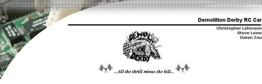
To transmit signals to the car we replaced the internal circuitry of the original remote control unit with our own 433HZ RF transmitter and Mega 32 MCU. There are two control joysticks on the RC unit; one for the back motor which controls forward/reverse directions and the other for the front motor which controls left/right steering. Each joystick is connected to a potentiometer whose output voltage changes depending on how the joysticks are moved, with respect to the midway reference voltage for when no direction/steering is chosen. For example, pressing forward on the “direction joystick” will produce a higher 3.6V voltage on the output of its potentiometer while pressing downward on the on the “direction joystick” will produce a lower 1V voltage on the output of the direction potentiometer. When the joystick is left alone, the output voltage of the potentiometer is at a constant midway voltage of 2.8V.
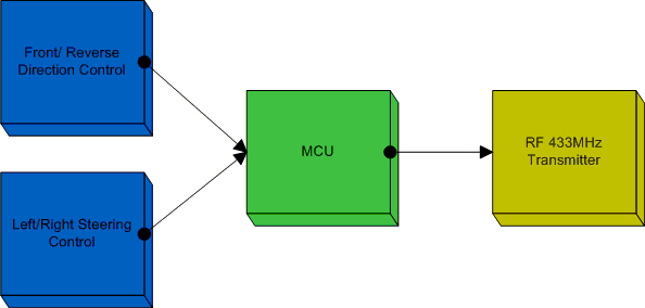
Figure 1: RF transmitter Flow Diagram
Each potentiometer is connected to its own ADC input pin located on the MCU. The MCU is coded in such a way that the ADC samples every 50 ms based on a timer 0 interrupt. However, since only one ADC pin can be
sampled at a time, the two pins take turns being sampled every 50 ms. Thus it takes 100ms to get a “truly” new direction and steering reading from the joysticks. Testing showed this was more then enough time to suffiently control the motors.
Immediately after taking an ADC sample from an input, the MCU scales the digital 8-bit ADC value to a 4-bit code value. The 4 bit-code contains the direction/steering information which will used by the car MCU. For this project we scaled and grouped the DAC values in such a way to only produce 2 variable forward/backward and right/left movements and 1 stop direction. This allowed us to have a 5 variable movement control for the forward/backward motor and the left/right motor. For example, in the case of the back motor the user can make the car go full-forward, forward at half speed, stop, back at full speed, and back at half speed. In theory we could have up to 15 variable movement controls for each joystick, but we keep it at 5 due to time constraints and signal sericuty
The two separate 4-bit code values are then OR'd together to create a single 8-bit character which will be transmitted to the receiver. We chose this method of encoding because it allowed the instructions to the direction motor and steering to be easily decoded and separated from each other. The first 4 MSB contain the steering information while the four LSB contain the direction information. To transmit, the 8-bit character is sent to the transmitter via the MCU's UART because the transmitter transmits according to the RS232 transmission standard at a baud rate of 4800. However, unlike the transmitter, the receiver requires an 8-bit pulse signal to initialize and correct itself every so often. To account for this, the transmitter transmits the 8-bit character 0xaa when ever no direction and no steering is selected. During transmission of any other direction and/or steering character 0xaa is transmitted every 5th consecutive transmission. This ensures that the receiver is highly responsive at all times.
The car unit receives RF transmissions though a 433Mhz RF receiver whose signal is then decoded by the car’s MCU. Like the transmitter, the receiver operates according to the RS232 standard at a 4800 baud rate. Signals taken from the receiver are sent to the MCU via the MCU’s UART receive pin and are read by the MCU when a UART receive interrupt is triggered.
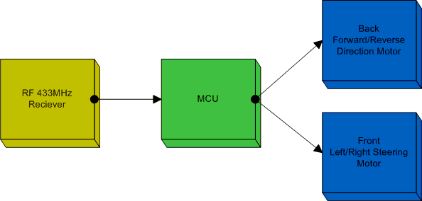
Figure 2: RF receiver Flow Diagram
The car’s MCU then breaks the 8-bit transmitted character into two separate 4-bit chars: the 4-bit back motor control and the 4-bit front motor control. Each 4-bit character is then handled and decoded separately in determining how to control their respected motors. In the case of the back motor, if no direction is selcted (i.e. the car is at "stop"), a kill signal is sent to the back motor control to ensure no forward or reverse direction.
The accelerometer we used was an Analog Devices ADXL250. This IC is capable of sensing +- 50 g’s on two axis. Zero g’s corresponds to a DC output on the accelerometer of approximately 2.5 Volts. Any acceleration causes the output voltages to swing relative to the acceleration, up to 5 Volts or 0 Volts.
We were unable to implement the accelerometer as a device for detecting collisions on our car, but we were able to get it working correctly. By sampling the accelerometer every 100 microseconds (each channel at 200 microseconds, each taking turns), we were able to read the accelerometer and detect collisions.
The back motor is a 10 to 15 volt DC motor that controls the forward and reverse directions of the car. The motor has 3 leads into it, a ground connection and two control leads. These two leads will connect up to the output of each side of the H-Bridge. The H-Bridge is controlled by a hardware PWM circuit. The PWM is created by comparing a hardware generated triangle wave to an input voltage, which is a control voltage from the MCU. The duty cycle of the PWM is directly related to the control voltage. If the control voltage is 2.5 Volts, then the duty cycle is 50%. Five Volts gives 100% duty cycle, while 0 Volts gives 0% duty cycle.
This PWM signal is fed into a set of NOR gates, which serve to invert a copy of the signal, sharpen the edges, and implement a logic shutdown control. If the shutdown control input is grounded, then PWM signal is able to pass through to the H-Bridge. If the shutdown signal is high, then the transistors in the output stage will be all turned off. In this way we are able to conserve current by not running the H-Bridge when not needed.
From the NOR gates, the signal passes through optoisolators, which then control the H-Bridge. The H-Bridge is comprised of IRF520 and IRF9520 power MOSFETs.
Figure 4: Back Motor Operation Flow Chart
Once the car’s MCU has extracted the 4-bit back motor control, the 4-bit code is mapped back to an 8-bit character value. The purpose of the 8-bit character is to convert the transmitted signal into a corresponding voltage value between the rails of 0 to 5 volts with the help of am 8-bit Bourn 4310-R2R-103 resistor network DAC. This voltage in turn goes on to set the duty cycle (and thus power output) of the back motor’s PWM.
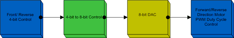
Figure 5: Back Motor Control Flow Diagram
For our project, there are 5 possible voltages that can be sent to the back motor because of the 5 variable movement control signals we restricted the remote control unit too. The mapping is as follows:
- Forward at full speed translates to 5.0V
- Forward at half speed translates to 3.75V
- Stop translates to 2.5V
- Reverse at half speed translates to 1.25V
- Reverse at full speed translates to 0.0V
The front motor is a servo motor which controls the car’s steering. Attached to it is a potentiometer which reads the servo motor to produce a feedback voltage that describes the state of the front wheels. The MCU on the car outputs 4 signals to control the front motor, and takes the feedback from the front motor as an input. The outputs of the MCU go into a 4 BJT H-bridge that allows the front motor to turn in two directions, right and left. Opto-isolators are placed between the MCU output and the H-bridge to eliminate additional noise. The H-bridge is driven by fixed length pulses to ensure that the servo motor does not turn the wheels too fast. There is no need for a formal PWM signal to control the front wheels. As a result, H-bridge will then turn the motor on, and depending on the input to the H-bridge, the motor will either turn right or left. As the motor turns, the potentiometer inside the servo motor turns as well. The potentiometer will output Vcc if the wheels turn all the way to the left, and will output GND if the wheels are turned all the way to the right. This voltage is feed back to the MCU through the ADC on pin A.1, which uses that feedback, and decodes it to compare it with the user input to either turn the motor on in one direction, or the another direction, or off.
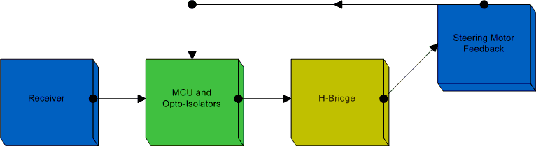
Figure 6: Front Motor Operation Flow Diagram
The MCU generates the four signals that control the H-bridge from pins 3 to 6 on Port D. Using the potentiometers feedback, the MCU will continue to adjust the 4 input signals to the H-bridge until the desired steering setting is reached. The signals are sent through Opto-isolators to reduce noise and then passed into a simple H-bridge that allows the motor to turn in both directions. Because there are 5 variable steering selections, the possible settings are left, half way left, straight, halfway right and right. A particularly tricky aspect of the entire setup is getting the correct resistance values in the resistor networks of the Opto-Isolator/H-bridge interface. After some experimentation we were able to determine that 10K resistors were the optimum choice.
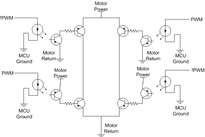
Figure 7: H-Bridge Diagram
The motor itself has six terminals. Three terminals are for the actual motor and three terminals are for the potentiometer to generate the feedback signal. Two out of the three terminals that control the actual motor are connected to the H-bridge, and the other is simply connected to GND. The three ends of the potentiometer are pretty standard. Two of them will determine the maximum and minimum values that the feedback will be able to have. We set those terminals to GND and 2.5 V respectively. And input the actual feedback terminal to PORTA.0 of the MCU for ADC. The reason the potentiometer is constructed to hit ranges between 0 and 2.5V is because the MCU ACD will convert voltages in that range when using the internal Aref in the MCU. In addition, the ADC is checked and then restarted once every time the main loops executes and right after the MCU has decoded the latest steering code.
Sadly, we were unable to complete our final goal of completing a remote control with force detection. Despite being a 3 man group and starting 4 weeks early, the project proved to be too large to incorporate everything we had hoped for. However, we were very pleased to at least rebuild a working RF car from the ground up using our own skill and ingenuity.
The car works surprising well. The RF transmitter and receiver respond with incredible accuracy as does the back motor. However, our front steering motor is a bit sluggish since the transistors we selected for its h-bridge are unable to supply a large enough current. In the future, we would use more powerful TIP transistors instead of our current 3904/3906 series BJT transistors.
To keep the car safe and from blowing up, heat sinks are used on the power transistors used in the back motor H-bridge to keep their temperature down. To prevent wires from shorting or moving around, all the circuit boards are securely fastened using duct-tape and what ever screws we didn’t lose.
We came across little to no problems with interference from other groups and their projects. Because our project uses RF we had expected to at least come across some RF problems at least once or twice. Surprisingly this never happened even when multiple groups were using RF in the nearby area. However, this might be because we happend to get a very strong RF transmitter/receiver pair where we caused all the RF interference. If so, we deeply reget any problems our RF transmitter might have caused.
The great thing about our project is that any just about any one can use it given that they can control a simple remote control. The only requirements are that you know the basic directions of forward, reverse, left and right, and that you are mechanically proficient and competent enough to simultaneously operate two joysticks with your thumbs.
Surprisingly our project was under budget. We credit it this to our tenacity for requesting free samples and luck for finding free parts.
| Part Type |
Cost |
| 2 5V Voltage regulator |
$3.00 ($1.50 each) |
| 8 Opto-isolators from Prof. Land |
$2.70 ($0.35 each) |
| 2 ATML Mega 32 MCUs |
One free; Second $8.00 |
| 1 Transmitter/Receiver Pair |
$5.00 |
| Accelerometer |
free |
| Transistors |
free |
| 3 large solder boards |
$7.50 ($2.50 each) |
| Op-amps |
free |
| Original Car/Remote |
free |
| Resistors |
free |
| Diodes |
free |
| Wire |
free |
| Solder |
free |
| Dremel |
loaned for free |
| Grand total: |
$26.20 |
Our design satisfied many of our expectations. Having a functional remote control vehicle in hand is definitely satisfying. However without further functionality our project does seem a bit generic. It would have been much better if we were able to implement additional features that you would not find in most commercialized remote control cars like performance degradation upon collision. We originally planned to integrate an accelerometer into our car and detect collisions with it; however given the time constraints we were unable to incorporate that into our design.
If we were able to do this project again, we would not start with a 3rd party car which has very few specifications about motors and circuitry and custom built parts. A great deal of our time and blown circuits were spent reverse engineering the two motors and remote controller. If we were to do it again, we would purchase a generic car body and new motors with well documented specifications so that we can speedily construct the remote control car and be able to implement additional functionality from there on.
1...to accept responsibility in making engineering decisions consistent with the safety, health and welfare of the public, and to disclose promptly factors that might endanger the public or the environment;
Our engineering decisions are consistent with the safety, health and welfare of the public,and we will promptly disclose any factors that might endanger the public or the environment.
2...to avoid real or perceived conflicts of interest whenever possible, and to disclose them to affected parties when they do exist;
Through our construction of circuits we have improved our understanding of many devices and the degree at which devices like transistors could destruct or catch fire.
3...to be honest and realistic in stating claims or estimates based on available data;
We properly contributed a lot of our ideas as originated from a group that did a very similar project last year. We looked at a lot of their results and ideas and accredited them as the originators of the ideas.
4...to reject bribery in all its forms
Our finished product will be available to anyone who wishes to try it, regardless of factors as race, religion, gender, disability, age, or national origin.
5...to improve the understanding of technology, its appropriate application, and potential consequences;
We diverted from our original idea of crashing cars in a Demolition Derby game to further ensure the safety of all personnel involved in the project.
Daren Zou:
Initial project research; Servo Control research; Front Steering Motor Control Code, Front and Back Motor Reverse-Engineering; Back and Front Motor Testing; Final Report Write Up.
Steve Lowe
Front and back Motor H-Bridge design and construction; Back motor PWM design and contruction; Front and Back Motor Reverse-Engineering; Back and Front motor testing; Accelerometer testing; Hardware Soldering; Final Car Construction; Final Report Write Up.
Christopher Lehmann
Stand alone MCU’s design and constrcution; Webpage, RF transmission design and RF coding/decoding code; Radio Controller Unit Reverse-Enginering; New Radio Controller; Back Motor Control code; Hardware Soldering; Dremel Master; Back and Front Motor testing; Final Report Write Up.
The following are the two spereate code files we used for the project:
A few pictures featuring us in our full glory:
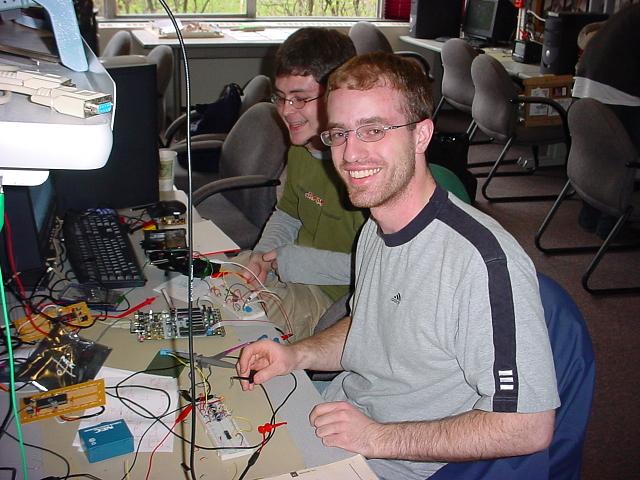
Steve and Chris hard at work on the car.
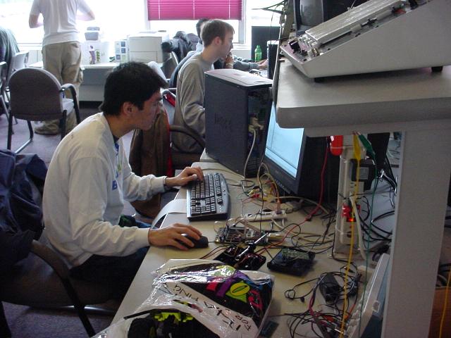
Daren hard at work on the car.
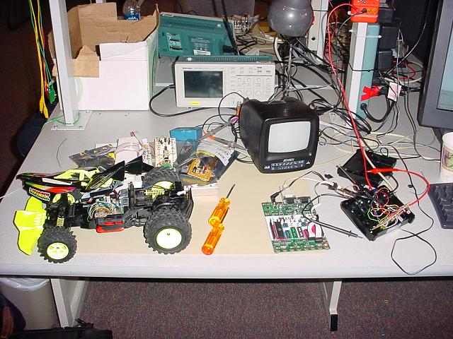
The orginal car before we "improved" it.
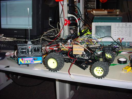
The final car after 4 weeks of "improvements" it.
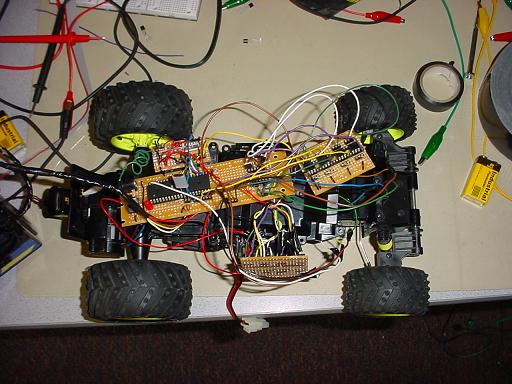
Our new car up close and personal.
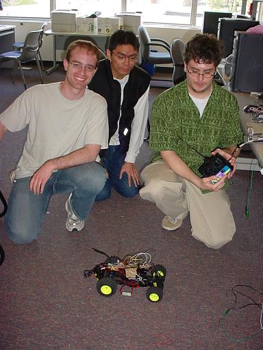
Steve, Daren, and Chris demo-ing the newly built car.