Electr-O-Sketch
By: Jason Levin & Chris Hopkins
Cornell University ECE 476
Spring 2004
Introduction - High Level Design - Design - Results - Conclusion - Ethics - Appendix
We created a project in which a user could control the movement of an Etch A Sketch using a typical serial mouse.
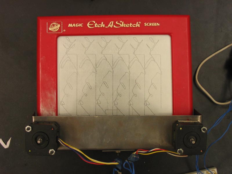
The public was introduced to the EAS in 1960 and since then it has stayed virtually the same. This nostalgic toy is recognized by many generations and we decided to put a new spin on the device. Most Americans are familiar with the two knob design which allows a user to control the movement of a stylus by turning each knob. The left knob controls horizontal motion and the right knob moves the stylus vertically. Turning both knobs at the same time causes the stylus to draw out a diagonal line. We decided to mount a stepper motor on each knob and control those with the Atmel Mega 32. By connecting a serial mouse to the microcontroller and using our line drawing algorithm, we could move the stylus directly by moving the mouse. The ability to record movements and play them back is available for creating more interesting designs.
In designing this project, we decided to create something that was a mix of mechanical and electrical components and would ultimately be fun to use. Using an EAS would be a throwback to our childhood but adding the mouse also revitalized the toy. Many students who saw us working with the EAS were immediately interested in what we were doing because it is such a popular childhood toy. Though the control of an EAS with a mouse is not necessarily a practical project, we thought it would be a good way for us to practice our engineering skills and would be something entertaining to do.
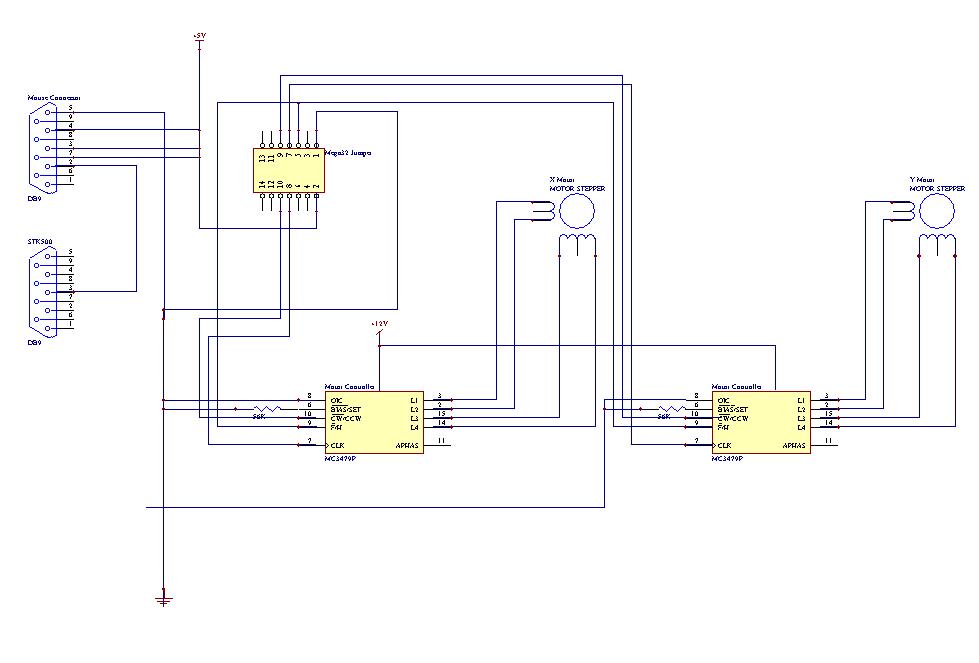
The source for this idea was an old 476 project that utilized 2 stepper motors on an EAS to draw pictures that were received from a computer via a serial connection. We wanted to work off of this idea, but let the immediate user create the picture with ease. A simple block diagram of the design is provided.
There were only a few tradeoffs that we ran into. The one major one being the choice of a stepper motor driver IC over that of several H-bridge resistor networks. The resistor network would simply add more complexity and a possible point of failure. By using the IC from Motorola we were able to simply output a few digital signals from the MCU and move the motors in any direction we want.
A small tradeoff in software was the use of automatic changing of the step size. Originally the step size was set via a button on the STK500, but once we realized that we could change this automatically with the amount of mouse movement, this was eliminated. The user is then not in direct control of the step size, but rather the software will do this for him/her.
We decided that it would be best to use a serial rather than a PS2 mouse in our project because of the simplicity of interface. For our purposes, the serial mouse would suffice and because the crux of the project was the actual control of the stepper motors, we decided not to worry about the PS2. PS2 is a synchronous bidirectional protocol which is much more complex than the serial mouse. However, in order for us to interface with a Microsoft serial mouse, it was crucial to understand the serial mouse protocol. First, it has a baud rate 1200 which is actually so slow that it is undocumented in the Atmel Mega 32 datasheet. We had to calculate the proper values for the USART register to read the data in at the correct rate. The mouse then sends data packets in groups of three bytes each with a single stop bit. To separate the packets, the first byte has a 1 in the second most significant bit whereas the other two bytes have a 0 in that location. The mouse transmits data each time it changes states, updating up to 40 times a second. Each packet contains information for the buttons and for how much the mouse moved in the x and y direction relative to its last position. Each directional movement is a byte in length and is in two’s complement.
The layout of the transmitted information is as follows, where X7..0 and Y7..0 are the change in the respective direction since the last update. LB and RB are the left and right mouse buttons, which are active high.
|
|
D7 |
D6 |
D5 |
D4 |
D3 |
D2 |
D1 |
D0 |
|
1 |
1 |
|
LB |
RB |
Y7 |
Y6 |
X7 |
X6 |
|
2 |
1 |
0 |
X5 |
X4 |
X3 |
X2 |
X1 |
X0 |
|
3 |
1 |
0 |
Y5 |
Y4 |
Y3 |
Y2 |
Y1 |
Y0 |
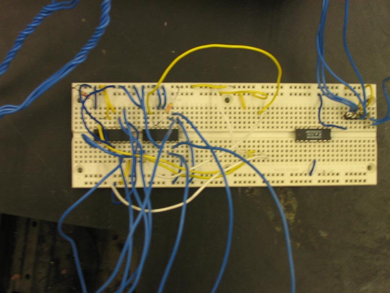
This originally posed a problem for us since we thought that the mouse would not be powered by the STK500 serial port. To work around this we decided to power the mouse from Vdd off the STK500 and run the TX line from the mouse directly into PORTD. This ended up not working since the output from the mouse is TTL serial and the Atmel will not recognize this. The serial port on the STK500 has some circuitry before connecting the input to the Atmel so that the signal is modified to correctly meet the specs of the Atmel USART input. To use the serial port and Vdd from the board, we setup a jumper on a whiteboard to give the correct voltages to the mouse and then output the mouse TX line directly into the RS232 port on the STK500.
The EAS name is a trademark of The Ohio Art Company as is the configuration of their product. We understand and respect the fact that it is trademarked and also a children’s product. In this project we are attempting to simply create an interesting control for such a beloved product and in no way would attempt to harm the image of the toy or company.
We also recognize the patents for the EAS and our serial mouse held by The Ohio Art Company and Microsoft respectively.
This project was created solely for academic use in Cornell University’s ECE 476 course and was not intended for profit.
The line drawing algorithm that was used was a variation of the Bresenham algorithm, since our design needed to use a plotting type function. The stepper motors need to turn in such a way as to connect 2 points in the xy-plane. This is very similar to that of connecting 2 points on a pen plotter or 2 pixels on a computer screen for basic graphics.
The only way a individual knob on the EAS can move is one step of the stepper motor in either direction, this corresponds to one pixel movement at a time. So the line can now be drawn from a single point either up, down, left, right or diagonal one pixel. This can be accomplished by moving one motor in either direction, or both motors in a direction to achieve a diagonal. Now that we can have a slope of 1, the task of creating the appearance of different slopes was tackled. To do this the EAS starts at the beginning point and finds the slope to the desired end point and tests if its greater than 1 and determines where to move one pixel. After this move is completed the start point is now the current location and the slope to the end point is re-evaluated in a loop until the end point is reached. The code to complete this can be made much simpler and quicker by adding in shifts and several variables to track the change with each movement.
To step the motors a Motorola MC3479P integrated circuit was used. This IC enables simple control of the MCU over the bipolar stepper motors. Since switching currents in the coils via an H-bridge or other methods was not desired and more difficult, the IC was used for quick, robust control. The main inputs to the IC are the step clock, step direction and the step size. The IC will output the correct signals to the motor once a rising edge of the step clock is seen. The step direction, clockwise or counter-clockwise, and step size, half or full step, have an effect on the signals from the IC at this rising edge. There is a certain setup and hold time for these signals before the step clock. To take this into account the outputs from the MCU to the IC were run on a TIMER0 run state machine. TIMER0 was set to go off every 0.25ms, or 250us, and thereby going through the state machine at a desirable speed.
The initial state sets all of the outputs to be 0, which holds the motors in the current position, and waits for a flag to signal that it is time to step the motors. The next state simply decides whether the slope is more or less than 1 and then sends the state machine to the correct path. The direction bits are then set on the appropriate state followed by a state which sets and holds the step clock high on the calculated motor’s input. The state machine then runs until the end point of the line is reached.
Timing for the step clock was figured out from the number of mouse inputs that were received in a second. Since there are a possible 40 mouse updates per second, this meant that for maximum resolution all of the stepping for a current mouse movement had to be completed in 25ms. By experimentation, it was found that the stepper motors would not have the required torque to move the EAS knobs when the stepping frequency was above 500 Hz. To keep the frequency below this, the maximum number of steps in a given mouse update was set to 10, and from there the hold time of the step clock could be calculated to allow the state machine to achieve accurate timing.
One of the problems we encountered in the final testing phase of the project was that the EAS lacked the precision we were hoping to achieve. Fine details were distorted or missing because of stepping problems. The original configuration of our code was designed so that a mouse while moving quickly would still be correctly drawn on the EAS. To do so required us to make long, quick steps so that the drawn line would be complete by the next update from the mouse (1/40 sec later). However this rush to cover large distances did not correctly interpolate fine details. Ideally, when the user desires fine detail, the motors could take more time and have shorter steps causing the picture to appear less discrete. We then modified the code to allow the user to switch between a fast, full step mode and a slow, half step mode. Following this, we realized that when a user is concerned with fine detail, he would be moving the mouse slowly, thus the original concern for not completing the line before the next update would be nonexistent. Current software checks the speed of the mouse and adjusts the step size to fit accordingly. Using a half step at the same clock rate, causes the motors to only draw half of the possible distance but gives twice the resolution. Switching between the two speeds may sound alarming, but it is not noticeable to the user. Hence newest code can switch automatically for the user to allow him to draw both fine details and large movements.
The reset position function is designed to center the stylus in the middle of the EAS from starting anywhere on the board. However without any feedback, the microcontroller would not know where the stylus is at any point in time. This is caused by slippage in the knobs and random positioning during startup. We quickly discovered a phenomenon of the EAS that allowed simplification in software. The EAS knobs can be turned even when the stylus has reached the edge of the drawing surface and amazingly will move back on screen as soon as the knob is turned in the opposite direction. Our state machine works by moving the mouse down hundreds of steps, so that the stylus ends up at the bottom of the screen. It then is moved left hundreds of steps so that it will end in the bottom left corner. The motors proceed to turn back to the right and then up a set amount of steps so that the stylus ends in the center of the screen. Thus the EAS can be centered without the use of any feedback.
The final feature we decided to implement on the EAS was the teach function. A user can press the record button and the microcontroller will remember the next 500 moves made. The EAS will continue to draw as usual, but following the press of the play button, the microcontroller will draw out the image that was stored. Our implementation begins by storing each x and y movement into an array once the button is pressed. The mouselookup and draw functions will continue to be called as usual and more values will be stored into the array. Once 500 values are stored or the button is pressed again, no more values are stored into the array. Following the press of the play button, the playback function disables the mouse and begins to read out the data in the two arrays. The draw function is called as usual and is fed the values from the array, rather than the mouse. This continues until all the values are read out and the EAS returns to its normal functionality.
The stepper motors that were chosen were part 163395CL from Jameco. They are bipolar 280 mA motors with 4 wire inputs. Through testing it was determined that they would supply sufficient torque to move the EAS knobs when moving at less than 550 Hz. This was the way we chose the maximum number of steps that could be done at one time, hence limiting the speed of the EAS movement.
The integrated circuit that was used was the Motorola MC3479P. This IC takes in a couple digital TTL inputs and outputs the correct voltages to the bipolar stepper motor. There is a Vm and Vd input which are the voltage that will be supplied to the motors, we chose this to be 12V, since a 12V power supply was readily accessible. There is then the digital inputs of direction, clock, and step size. The last input is the bias input which is connected through a 56k resistor to ground. This size resistor was chosen through the following calculations, based on 280 mA rating for the motors.
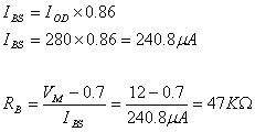
So a 56K resistor was chosen to be on the safe side and not run the motors at the maximum current.
The mount for the motors was made with 0.040” scrap sheet metal that was procured from the outside the GM Auto Lab. This was then cut and bent into a shape to hold the motors in the correct position on the EAS. A set of 4 nuts and bolts was then found in the miscellaneous bolt bucket inside the GM Auto Lab. This was all assembled to securely fasten the motors once the couplers were mounted. The couplers were purchased from Jameco and fit the stepper shaft as well as the shaft on the EAS. A rubber spider was then inserted between the couplers to allow removal of the metal mount for adjustments.

The speed of the program is such that it has no negative effects on the system. The mouse is only updated 40 times a second and the motors are stepped just as fast. This code does not rely on the speed.
The accuracy of the motors is only as good as the speed at which they are limited. They are limited to 400Hz which is not ideal. If the motors could move faster the usability would be higher. The changing step size with the amount of mouse movement increases the usability since the user can draw very small details and then still have the speed to make long lines very quickly. The accuracy of replaying the movements that have been recorded is rather good, the only drawback is the occasional slippage in the motors. This could be improved greatly with higher torque motors and a mount that was more professionally made.
With respect to safety, there is little concern for either mechanical or electrical problems. The mount for the stepper motors was designed so that it enclosed the majority of the moving parts. The motors also have fairly low torque compared to something that could be harmful. Because we used motors, we did have to use a larger power supply at 15 V providing roughly 280 mA to each motor. If this toy were to be designed for children the proper enclosures would have to be fabricated to prevent any risk of shock. However as electrical engineering students taking care in the lab, we had no safety problems.
The design did not use any RF transmitters in our design that would cause problems with other groups. We also did not notice any problems with other groups around us regarding RF or cpu noise.
The results of this design met all of our expectations and even exceeded them. Originally we had hoped to only be able to get the mouse to control the stepper motors and draw simple lines on the EAS. With the addition of a simple and efficient line drawing algorithm this was taken care of and we could proceed to work on more complex features. The speed control and ability to record and playback were not even thought of at the start of this project and worked well enough to be included in the final design. The accuracy of the mouse to draw on the EAS was also better than we had expected initially.
This design did not use code from anyone else, whether it is the internet or past projects. The design also incorporated no reverse engineering, and has some possible patent opportunities. A working electronically controlled EAS may be a product that people would want to buy…..

1) “to accept responsibility in making engineering decisions consistent with the safety, health and welfare of the public, and to disclose promptly factors that might endanger the public or the environment;”
We have kept safety in mind throughout the design of this entire project. In no way do we feel it will cause harm to any person nor is there anything that could end up harming somebody.
3) “to be honest and realistic in stating claims or estimates based on available data;”
All statements made in lab and on this webpage have been honest and the content of the pictures on this site have been unaltered.
6) “to maintain and improve our technical competence and to undertake technological tasks for others only if qualified by training or experience, or after full disclosure of pertinent limitations;”
We undertook this project with the goal of expanding our knowledge of electrical engineering yet knowing that we were qualified to take such a venture.
7) “to seek, accept, and offer honest criticism of technical work, to acknowledge and correct errors, and to credit properly the contributions of others;”
We were open to advice of those who critiqued our work, most notably the design of our mount. Input from mechanical engineers during our fabrication of this mount was very valuable.
9) “to avoid injuring others, their property, reputation, or employment by false or malicious action;”
Though we worked in tight quarters in the lab, at no time did we modify or destroy any other student’s work.
Parts list
|
Part Description |
Part # |
Quantity |
Price |
Total |
Supplier |
|
|
|
|
|
|
|
|
Stepper motors (Bipolar) |
163395CL |
2 |
$4.95 |
$9.90 |
Jameco |
|
Etch A Sketch |
|
1 |
$0.00 |
$0.00 |
Old parts |
|
Serial Mouse |
|
1 |
$0.00 |
$0.00 |
Old parts |
|
Aluminum coupler |
161998 |
4 |
$1.09 |
$4.36 |
Jameco |
|
Rubber coupler |
162000 |
2 |
$1.29 |
$2.58 |
Jameco |
|
Atmel Mega 32 |
|
1 |
$8.00 |
$8.00 |
|
|
Breadboard |
|
1 |
$5.00 |
$5.00 |
|
|
Stepper motor drivers (Motorola IC) |
MC3479P |
2 |
$3.38 |
$6.76 |
Digikey |
|
RS232 male connector |
|
2 |
$0.30 |
$0.60 |
Clark Stockroom |
|
0.040" sheet aluminum & screws |
|
1 |
$0.00 |
$0.00 |
FSAE Lab |
|
12V Power Supply |
|
1 |
$0.00 |
$0.00 |
Old parts |
|
|
|
|
Total |
$37.20 |
|
Tasks
The entire project was carried out entirely with both of us working on a topic at the same time. When making the mount each of us would be doing a task to complete the design. While writing code we would switch off times typing and doing the hardware debugging. The website was also written together and then designed by Jason.
References
Motorola MC3479P Stepper Motor Driver Datasheet-
http://www.leang.com/pat/umouse/datasheets/mc3479.pdf
Jameco –
Digikey –
Serial Mouse info –
http://www.hut.fi/~then/mytexts/mouse.html
Etch A Sketch –
http://www.etch-a-sketch.com/html/
Stepper Motor –
http://www.jameco.com/Jameco/Products/ProdDS/163395.pdf