A Wand Based Barcode Scanner
An ECE476 Final Project from:
Wyatt Schweizer (wws6)
Mike Fenn (mtf23)
Introduction High Level Design Program/Hardware Design Result Ethics Conclusions Appendix
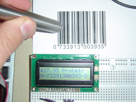
Introduction: Our project is a UPC-A Barcode Scanner complete with a pricing/description database interface.
Our original goal for this project was to build a standard
barcode scanner from scratch, but as the project evolved so had to our
specification of the project. We
initially sought to build a charge-coupled device (CCD) scanner, which scans the
entire barcode at once. This,
however, required parts beyond our budget, namely a high-resolution CCD array,
as well as knowledge of optics well beyond our own.
We then shifted our focus to a pen or wand style scanner, where the user
drags the tip of a pen evenly across the barcode to read it.
This, however still required substantial optical work.
We discovered that we could purchase a “dumb” scanner wand on E-bay
for around $10, thus our ultimate implementation.
The so-called “dumb” wand simply gives the user a TTL output stating
whether it is reading from a black or a white surface.
This essentially shifted most of the design challenge from optics to
software, especially error correction, which we felt was more appropriate
considering the nature of this course.
The major design challenge we encountered surrounded
dealing with the inaccuracy of the initial readings.
Because of the small size of most barcode features, only a few samples
could be taken over some of the smaller ones during a pass with the wand.
This necessitated substantial error correction to attain reasonable
accuracy for a given scan. The
nature of the wand scanner, as even detailed by commercial producers, requires a
steady and well-trained hand to scan.
1.
Idea and motivation
There was no real spark for the idea to build a barcode scanner, it just seemed
like an interesting and challenging concept for a project.
2.
Design Overview
We approached our design process by working separately on two distinct fronts
and merged them once each was complete and functioning in isolation:
reading the barcode and decoding it.
Reading the barcode: This
task centered around first learning the capabilities of our wand scanner.
Its interface is simply an open-collector TTL output which reads at 5V if
the scanner is over a black bar and 0V if it is over a white space.
The scanner itself features a red-light phototransistor and a red LED
focused through a lens. The
phototransistor will detect if the light is reflected off the surface below,
thus reading a white space in the barcode.
The trick to reading one of these barcodes is tracking the number of
white/black transitions. As
detailed earlier, each section of the barcode is guaranteed to have a certain
number of these transitions, effectively clocking the scan. We used a state machine to track the transitions and detect
where the wand is in the barcode. The
relative widths of each segment (bar or space) in each digit section gave us the
7-bit encoding for each digit, which can then be decoded.
We approached this part of the design by first tackling the
parts over which we would have complete control before introducing the
uncertainty of the scanner. I began
working with a standard C compiler to test code to handle the transformation of
the relative widths of the bars and spaces into the 7-bit encoding by using some
simulated reads. I later found out
that due to code speed I would not be getting so many samples, which introduced
the need for error correction.
3.
Hardware/Software tradeoffs
We shifted most of our design challenge from hardware into software, mainly
because those particular hardware challenges would have been primarily optical
in nature and likely require precision equipment to which we did not have
access. Had we been able to scan
the entire barcode with a CCD array in one shot, we would not have had the error
variable of the user dragging the wand. Had we been able to build such a scanner, our accuracy would
have greatly improved. But again,
after much evaluation we deemed it an unreasonable goal.
To compensate for this, we had to develop a multi-stage error correction
algorithm, which greatly improved the scanning success rate.
4. Standards
EAN-13 Barcode:
The EAN-13 encoding is split up into four groups:
Fig 1: A EAN-13 Barcode with each character shown in alternating colors
Picture from: http://www.barcodeisland.com/ean13.phtml
After scanning the barcode, it must be verified as valid. This will be accomplished by calculating the checksum on the first twelve digits and comparing the output to the checksum digit. This will be extremely valuable in our testing process. We have decided that if the checksum fails then we will rescan twice before sending an error to the user. This scheme is meant to increase the accuracy of the Barcode scanner making life simpler for the human operating it.
NOTE: Due to error correction considerations, our barcode scanner will only read UPC-A Barcodes, which are a subset of EAN-13 Barcodes. This simplifies one dimension of the encoding allowing for more accurate error correction.
RS-232 asynchronous serial communication:
We used the RS-232 standard for our serial communication with the PC just as in earlier labs in the class, by hiding the the output interface through the use of the standard input/output library in C. We then implemented the input interface with a non-blocking receive interrupt mechanism, as done in in Lab 3. This serial interface served as the link for our emulated database.
5. Intellectual Property considerations
The only intellectual property consideration surrounds our use of another company’s wand scanner, so our product could be marketed as a decoder for it. Otherwise all of our ideas and methods were original. The only code that was not completely original dealt with receiving characters from the USART from the Security System lab.
Program Details:
For the sake of versatility there are two compile-time
options, implemented through the frequent use of the #ifdef directive, built
into the program: a debugging mode and a terminal interface mode, each of which
makes use of the serial connection to a PC.
Debug mode: Displays
a plethora of important information regarding the scan on the PC terminal.
This was incredibly useful when evaluating scanning accuracy and
developing error correction. By watching for trends in the errors we were able to discern
patterns that directly influenced the error correction schemes, especially the
favoritism toward correction to a width of four, as described earlier.
Terminal mode: This
mode adds the serial interface to the terminal used to emulate a database system
for the scanner. If this mode is
off, the LCD simply displays the UPC number and the country of origin.
When this mode is activated, the MCU sends the UPC to the terminal, which
could then be used by a database to return the relevant product information.
For our emulation, a user can type in the information for which it is
prompted, including price and a product name, which are sent to the MCU and
subsequently displayed on the screen.
The guts of the program is split into two major segments,
one handling the reading of the barcode and the other decoding that data into
the actual barcode and displaying the information, including that received from
the terminal.
Barcode read:
We immediately recognized that we would need an organized
program to read in the barcode digits piece by piece and to do so quickly to get
enough data samples. This immediately suggested the necessity of a state machine
driven by a compare match interrupt on Timer1 running as fast as possible,
effectively running as software polling. To get optimal performance, we deactivated the register save
on both the ISR and the state machine update and designed them such that they
used only global variables. Therefore
we needed only to save and restore the status register on each call, saving
approximately 60 cycles per call. The
ISR read from the scanner on PORTB tracked both the current and previous read to
watch for transitions. Upon reading
the first three transitions, the scanner has finished the left guard and has
moved on to the left-side digits. These
digits each contain four bars/spaces, whose widths are recorded by the ISR which
counts the time between each subsequent transition.
Upon finishing the sixth digit, the state machine watches for the five
transitions of the center guard before reading the right digits in the same
manner as the left. The barcode
then finishes with a three-transition right guard bar.
Because a user can abort a scan at any time by lifting the pen or
stopping it, the state machine required a timeout mechanism to reset it and be
ready for the next read. Because transitions are expected, the timeout check simply
check to see if there has been a specified length of time since the last
transition.
Once the widths have all been recorded, they must be
reduced to their 7-bit encoding, so effectively the widths must be scaled down
to a total width of seven. Because
so few samples are taken, there is an interesting problem created by integer
math; often the numbers will not work out perfectly and adjustments will need to
be made. First, any width that
evaluates to zero is automatically increased to one and likewise any width over
four is reduced to four, since otherwise the scan would be invalid.
Second, and also a consequence of integer math, if the scaled width is
still less than seven, then the closest bar or space which is the next closest
to the next step up is incremented; this is achieved by checking the size of
remainders. This step is carried
out until that total width of seven is reached.
Error Correction:
These relative widths are then easily converted into a string of seven bits for that digit. The most difficult part of this process follows: error correction. Because of the crudity of a wand scanner, a clever method of error correction is necessary, using the one guarantee: parity. First, for the UPC-A standard, every digit on the left hand side of the barcode must be encoded in “odd parity,” and every digit on the right in “right parity.” These parities define the set of bit strings for each number to which a digit might evaluate. If a particular scanned digit does not meet the parity requirement, it must be error corrected. Our error correction method is based on the reasoning that most errors are likely to be single bit errors, in that no width will be off by more than one. So, the software iterates through all possible combinations of single-bit adjustments until it finds the first parity match, which is then tried by the decoder. However, these results were not satisfactory. For each misread, there are several single-bit corrections that will yield the correct parity – and only one will be correct. This suggested the possibility of examining every combination until one passes its checksum. However, we decided that there was too great a risk of returning a valid barcode that is still incorrect. We felt it safer to have the error in that case. So, we opted to examine patterns in the errors and found one major one. The scanner had a tendency even out the relative widths of the bars and spaces, that is in many cases where two segments should have been read as widths of four and one, they are instead seen as a three and a two. So, before searching for the first single-bit adjustment, the code automatically looks for this condition and tests that adjustment for parity. This addition to the error correction scheme fixed more than half of the errors. Note in the example figure below, output from the debug mode terminal, the transformation of the digit widths and where they are “reformed” to match parity, which yielded the actual valid barcode.
--------------------
Fake Barcode Database!
---------------------
-DEBUG MODE-!
4,12,4,8, => 1,3,1,2,
3,15,4,3, => 1,4,1,1,
3,14,3,4, => 1,4,1,1,
8,3,3,5, => 3,1,1,2,
6,6,5,3, => 2,2,2,1,
2,11,3,2, => 1,4,1,1,
8,6,3,3, => 3,2,1,1,
8,5,2,3, => 3,2,1,1,
2,9,3,2, => 1,3,2,1,
reforming... 1,4,1,1,
9,3,2,5, => 3,1,1,2,
3,9,3,3, => 2,3,1,1,
reforming... 1,4,1,1,
3,5,7,3, => 1,2,3,1,
UPC = 0733913003935 (USA & Canada)
Enter price: 29.98
Enter Name(MAX 8 char):Scanner
Figure: Example of Terminal Output on HyperTerminal when both Debug and Terminal mode are on.
Barcode decode:
A barcode is organized into two equal halves seperated by a
center guard. This center guard consists of five lines of the form 01010, where
0 represents a white line and 1 a black line. For the EAN-13 format, everything
to the right of the center guard is encoded using a Right-Hand Encoding and
everything to the left of the center guard is encoded using a Left-Hand Encoding
. The Left-Hand Ecoding can be either Odd or Even parity.
Note: In UPC-A Barcodes the Left-Hand Encoding can only have Odd parity. There
does not exist an Even parity Left-Hand Encoding for UPC-A.
A EAN-13 Barcode consists of 13 digits, but only twelve are directly encoded.
The first digit is encoded in a special way. The first digit decides the pattern
of Odd and Even parity in the first 6 encoded digits. This mean that the first
digit can only be decoded after the the next six digits are already decoded. In
order to find the first digit, we had to keep track of the pattern of Odd and
Even parity encodings. The Right-Hand Encoding doesn't distinguish between even
and odd parity.
The Barcode decoding is done by keeping arrays of all the different possible digit encodings in memory. When we try to decode something to the left of the center guard, we look at all Left-Hand Encoding and find one that matches what we have. This tells us both what the digit is supposed to be and the parity used to encode it. By keeping track of the Odd/Even parity of each digit we can identify the pattern and thus the first digit. When we decode something to the right of the center guard, we always check the Right Hand Encoding, which is also in memory. After we have decoded all the digits, we caclulate the checksum and compare it to the the decoded version. If they match we return a properly decoded barcode. If at any point, the decoder cannot match an encoding or if we fail the CRC check, then we print an error to the LCD so the user knows to try again.
The checksum is calculated by taking all the decoded digits, multplying every other digit by 3, and adding everything together. The checksum value is the digit that makes this result evenly divisible by 10.
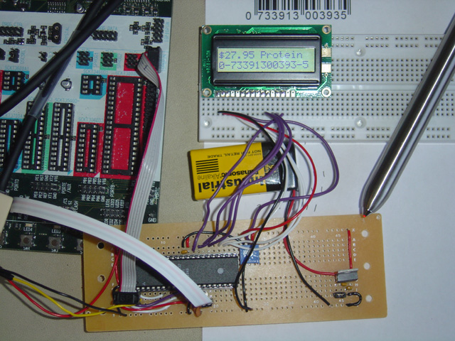
Hardware details:
Accuracy:
The major fault in the accuracy arose from the lack of samples on each bar or
space segment in the barcode digits. However,
we were able to adjust for this error reasonably well.
Once a user has been trained and practiced at scanning with a wand, they
can expect accuracy of 80% or more. Very
seldom will the scanner read a barcode and return a valid barcode that is
different from what it should have read.
Safety:
The only real safety considerations with such a device would be of a financial
nature. Imagine, for example, if
one goes to buy a TV and pays on the price of a pack of gum.
We feel that we enforce safety well by not error checking too
aggressively, which could lead to exactly this circumstance.
For the entire set of single-bit corrections on each digit, it is
expected that some will have a valid checksum!
By being somewhat conservative with our error correction, we make this
highly unlikely. Otherwise there
are no real dangers with out device.
Usability:
At this stage, our scanner is not accurate or rapid enough to compete with the
other available types of scanners; these include the CCD scanner discussed
earlier, as well as the laser-based scanners.
Our scanner compares reasonably well to other wand scanners, thought its
accuracy is likely somewhat lacking. It
is, however, still functional even if it requires an extra scan here or there.
A. to be honest and realistic in stating claims or estimates based on available data;
We have taken great care to guarantee that our project has been
honest about both its successes and its failures.
1. We can accurately read a UPC-A barcode most of the time.
2. We fail to accurately read a EAN-13 barcode that is not
UPC-A most of the time.
B. to avoid real or perceived conflicts of interest whenever possible, and to disclose them to affected parties when they do exist;
The UCC Council has
announced that as of Jabuary 1, 2005 all barcode scanners must be able to read
EAN-13 Barcodes. This was done to make it easier for foreign products to be sold
in the US. If we were to try to market our product, it would be unfair to the
consumers if we did not disclose this fact.
C. to seek, accept, and offer
honest criticism of technical work, to acknowledge and correct errors, and to
credit properly the contributions of others;
Throughout the project development we continually discussed our project
between ourselves, with our TA, and with our professor. We have added references
at the bottom of this report for any websites that we used for our project and
discuss intellectual property considerations. We have also acknowledged that our
barcode scanner does not always scan the barcodes properly.
D. to assist colleagues and co-workers in their professional development and to support them in following this code of ethics.
Whenever we were in lab, we often spoke with other groups about there projects. This included what if any problems they were having. We gave suggestions as to things they might try, most of which had already been tried. But in general, we were civil, supportive, and helpful.
E. to reject bribery in all its forms;
We saw through Professor Land's cunning attempt at bribing us with free points for finishing early. We have prepared our demo for the day it is due, not early and not late. We will not accept any free points.
Results vs. Expectations:
Our results met our expectations reasonably well. We maybe expected a little more consistency with our accuracy, but we did not foresee the limitation on our ability to sample quickly over such small physical features while moving the wand at a steady but quick pace. After realizing we would need to switch to the wand-based scanner, our expectations were lowered. We rebounded well with our error correction schemes and were able to easily meet our adjusted expectations from that point. If we were to approach this problem again we may consider writing in assembly all of the code must be executed on each read. We might first analyze the situation again to be certain that code speed is indeed the problem, considering that there is not too much code that executes on each interrupt.
Conformity to standards:
We had no difficulty in conforming to the RS232 standard,
as it is very straightforward. We
were also able to successfully implement our UPC-A standard barcode scanner.
Our efforts to internationalize the design for the EAN-13 standard, a
superset of UPC-A greatly hindered our accuracy.
EAN-13 does not guarantee uniform parity of the left-hand digits, which
greatly tied the hands of our error correction algorithm by doubling the set of
valid bit strings.
Intellectual property considerations:
All of our ideas and algorithms for reading the barcode were completely original and we reused minimal code from the security system lab dealing with the USART. Since all of our algorithms for approaching the barcode scanning process were original there would be opportunities for both design patent and copyright protection for some of the software. However, we do not feel that our results were outstanding enough to merit such pursuits.Appendix A: Program Listing
barcode.h
barcode_decode.c
barcode_read.c
Appendix C: Cost
| Parts List: | Cost: |
| MSH-119 Wand scanner (E-bay) |
$10.00 |
| Atmel MEGA32 MCU |
$8.00 |
| LCD-64 display |
$5.00 |
| Large solder board |
$2.50 |
| LM340 regulator |
$1.00 |
| RJ-11 double socket (found) |
Free |
| 6 x 0.1uF capacitor |
Free |
| 2 x 22 pF capacitor |
Free |
| Trimpot potentiometer |
Free |
| 16 MHz crystal |
Free |
| Headers and jumpers |
Free |
|
Total: |
$26.50 |
Appendix D: Tasks
Mike:
-
Identified the particular barcode scanner wand as the basis for the
project.
-
Developed all of the code for reading from the barcode, including the
transition-based state machine and the relative width transformation
-
Developed the error correction scheme and found patterns in the chaos of
the errors themselves.
-
Added the serial interface for the database emulation.
-
Built standalone solder board.
-
Wrote the relevant sections for this report.
Wyatt:
- Developed all the code for decoding an
encoded EAN-13 barcode.
- Added the LCD as a display for the user.
- Created the Webpage layout.
-
Tested LCD output, barcode decoding, and webpage links to guarantee
proper outcomes.
- Wrote relevant sections for this report.
Appendix E: References
Barcode Island - This site describes almost all the different Barcode Standards in existence and was a valuable tool during our project.
Datasheet for LCD - This is a .pdf of the datasheet for the LCD we used in our project. This link can also be found on the ECE476 website.
Datasheet for Opticon MSH-119 scanner wand - This is a datasheet for the wand scanner we used for our project.