Fig. 1 - plotter space definitions
High Level Design
The Non-Orthogonal Plotter was inspired by the Vertical Plotter project completed in Spring 2001. We adapted the idea of using two motors in a non-orthogonal fashion from this project, but built a horizontal version of it and significantly extended its functionality. As in the Vertical Plotter, the motors on our project are controlled through software that makes use of simple calculus and differential equations. Based on the desired user-function, this math controls the rotation speed and direction of the two stepper motors. These two motors are connected via fishing line to a center piece which holds the pen. The user can navigate through the menu to perform the various functions of the Non-Orthogonal Plotter.
Because of the geometry of our project (diagrammed below), we used the rules of right triangles to determine the change in the hypotenuse of a triangle given changes in the other two sides.
Fig. 1 - plotter space definitions
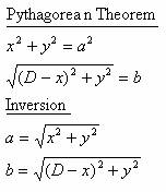
The following math shows how the Pythagorean Theorem was used to find equations for a and b in terms of x and y.
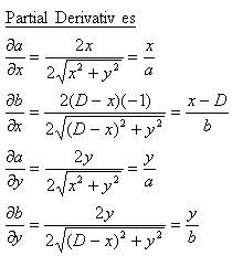
The next equations show the partials derivatives of each string with respect to each dimension.
This last set of equations shows the partial derivatives in Jacobian form.
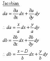
With this last set of equations, we now have a very useful relationship between the changes in the strings and the changes in the coordinates. In fact, this is all we need to make our motors move as desired. Since we will know the current values of a, b, x, and y, and can choose dx and dy as desired, we have all the information necessary to change a and b correctly.
The pen in this project is controlled by the motors, which in turn are controlled by the software. There are four possible modes the user can choose from, free draw, plot coor, plot text, and plot prog. The software uses a large state machine which changes states depending on the current state and the buttons pressed by the user. Based on the state it is in, the software accepts information from the user, prints messages to the LCD, rotates the motors, and turns on/off the solenoid. Because we know the steps the motors takes per centimeter of the string, we are able to keep track of distance on the board. This allows us to indicate when the user is going out of bounds. It is also the key information which allows us to draw lines of specific lengths and angles.
The only real trade-off we were confronted with was related to the speed at which we incremented steps in the motors. We discovered it was much easier to control the drawings and solenoid at slower speeds for the user. Slowing down the motors was also necessary to allow the hardware to physically keep up with the fast-paced software.
There are a couple traditional xy plotters that we have found. The following are the links to the websites for these plotters.
The most similar plotter to ours is the one completed in Spring 2001, called the Vertical Plotter.
However, our design is unique because not only is it unconventional by being non-orthogonal, but it is also horizontal.