
INFRARED TRACKING SYSTEM
Cornell University
ECE 476 Final Project (Spring 2004)
Arun Israel (aai2@cornell.edu)
Reda Dehy (rd73@cornell.edu)
Introduction High-level Design Hardware Software Results Conclusions Appendix
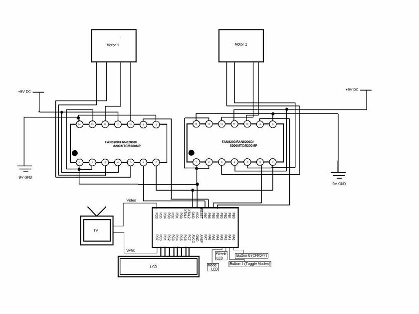
Our project is an infrared (IR) tracking system. A beacon, placed on the object to be tracked, continuously emits infrared signals in all directions. The signals coming from the beacon are detected by 2 IR receivers mounted on 2 stepper motors, which rotate independently and are in separate locations. The direction each receiver is pointing towards allows the CPU to determine the position of the beacon via triangulation. The position of the tracked object is then displayed on the TV, where the center point is the middle point of the 2 receivers, and the distance and direction are displayed on the LCD.

Figure 1. Basic system organization
Idea and Motivation:
Our initial idea was to design a system
consisting of an emitter and a receiver which would keep track of the emitter.
We wanted to build a cheap beacon that you could throw in a car or laptop, or
attach to your pet (or maybe individuals?), and be able to monitor its motion on
a screen in real-time, similar to those gadgets in spy movies. Our goal was not
to locate very accurately where the tracked object is, but rather to alert the
user when the object is undesirably moving (car being stolen) or moving outside
a given perimeter (pet has escaped), and give enough location information to
allow plain tracking and/or recovery of the object.
We originally considered Radio frequency, since its range
is good enough for the applications we had in mind and it goes through walls so
can be used outdoors. Similar existing system are GPS (using satellites), and
Radio triangulation (using antennas on buildings), but these are very expensive
(over $600 for Lojack car security system). Since there is no accurate unvarying
relationship between signal strength and distance, we decided to use 2 rotating
directional antennas. However, we quickly abandoned RF because of the issues of
cost, multipath, fading, interference from other sources, and the difficulty of
making reliable directional antennas. So we decided to use infrared instead.
However IR requires line of sight, so we could only test it indoors, and within
a small range. Since IR emitters are very directional, we just placed several of
them to point in all directions.
Search algorithm:
When the system is turned on, the 2 motors start turning in opposite directions until an IR source is found or a full rotation is completed. The motors stop independently when each sensor detects the beacon, and the motors remain while the beacon is not moving (low inputs from the IR receivers). Once the input gets high (target moved), the motors immediately turn a few steps in one direction, then in the other direction, increasing the step size every time until the target is found again. The motors “remember” the previous direction they had to turn in, so that next time it starts looking in that direction first, because we are assuming that if the target is moving, it is more likely to keep going in the same direction. This enabled us to continuously keep track of fast moving object.
Triangulation:
From the diagram below (Fig. 2), it is not difficult to derive the coordinates for the position of the target beacon. We used the following equation to determine the beacon position:
x = d* (cos(α1)*sin(α2)/sin(α1+ α2) – 1/2)
y = d* sin(α1)*sin (α2)/sin(α1+ α2),
where d is the distance between the 2 motors and α1, α2 are the angles each motor makes with the line connecting them. The distance D of the beacon from the center point is then given by:
D=(x2+y2)½

Figure 2. Coordinate system used in our project to track the beacon
Hardware/software tradeoffs:
Since we made use of the NTSC video code, we had to adhere to strict timing requirements in the software. To this extent, it forced us to keep the interaction between hardware and software as minimal as possible. We tried to be as conservative as possible and only kept the code that was absolutely vital to our application. The result of this is that the hardware became slightly more complex to make the software simpler. For example, we used control circuitry to handle operation of the bipolar motors which made the software simpler as we only needed to specify two outputs per motor instead of four. Also, we used the LMC555 oscillator to generate the 38kHz infrared wave on our emitter object. This hardware saved us from having to generate the signal in software and simplified our lives greatly.
Intellectual property considerations:
We did not explicitly reuse code from
earlier projects or anything found on the web since the majority of work we
found online involved the use of unipolar motors while we built our project
around bipolar motors. The difference lies in the control circuitry we had to
use (FAN8200 vs. ULN2003) as well as in the pulse sequences that need to be
generated by the control circuitry. The video code we used was provided to us by
Professor Land. We did not reverse engineering a design nor did we use anybody
else’s design. As far as we could tell, no earlier project attempted to track
and find an object using infrared sensors. We do not believe there are patent
opportunities for our project as there exist more sophisticated tracking devices
already on the market (GPS, etc) with greater range than our small scale system.
We did not encounter any existing patents, copyrights or trademarks
which would affect our project. All code referenced in our project was available
in the public domain and we credited all sources we used in the project. There
are no copyrights or patents on the search algorithms we used to track the
moving object.
Standards:
Our
project requires the use of a black and white television (provided by lab). As a
result we followed the EIA RS170 and NTSC video standards. EIA RS170 is used to
generate black and white video signals for televisions in the US, (different
standards apply in Europe and in the rest of the world). This standard specifies
three different voltage levels (sync, black, and white) as well as two sync
pulses for horizontal and vertical alignment. The voltages levels we used were
white = 1V, sync=0V, and black=0.3V. We followed the schematic given to us in
Lab 4 to achieve this voltage levels using a resistive network. The NTSC
standard specifies 525 lines/frame with a frame rate of 30 frames/second. NTSC
uses interlacing to reduce flicker. This is accomplished by displaying the odd
lines first then the even lines. In the video code provided to us by Professor
Land, this is modified since we are displaying only about 200 lines (100 odd
lines, 100 even lines). There are no applicable standards for infrared
transmission in our project since we are simply sending out an IR signal and
attempting to determine its location
The IR Emitter:
The IR emitter is simply an LED which emits light with wavelength typically around 950nm. Our first dilemma was to choose between IR phototransistors (transistors acting as variable current sources with the base voltage determined by the amount of light hitting the transistor) and IR modules (whose outputs are normally high and are set low when an IR signal at a specific frequency is detected). We tested both types of receivers, and we found that IR phototransistors were very sensitive to daylight and had a very small range of usage (it would not detect any signal coming from a source more than 5 cm away). The IR modules, on the other hand, are quite robust and detect signals farther than 3 m, but the transmitted signal needs to be frequency modulated. Another disadvantage is that the output of the modules is either high or low, whereas it is analog for the phototransistors, which would have allowed us to quickly determine whether the receiver is rotating in the right direction (the signal would get stronger) while searching for the beacon (as it moves, the signal strength goes down).
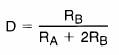
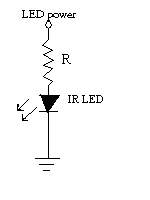 IR emitter |
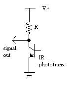 IR phototransistor |
Figure 3. Schematics of IR emitter and IR phototransistors
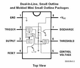
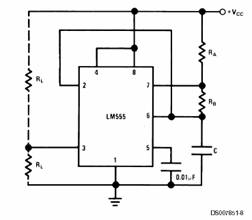
We used a LM555 with a 9V battery to drive 6 IR LEDs emitting in 180° (with 36° between LED directions). We tested a 180° angle IR LED, which does indeed radiate in every direction in a half-plane, but it had a very limited range (a few cm). We used the LM555 (from National Semiconductors) in astable mode (in which it triggers itself and free runs as a multivibrator) to generate a square wave at 38kHz. We used the circuit shown below (Fig. 3) as a starting point for our emitter. The circuit we built is shown in at the bottom of figure 3.
![]()
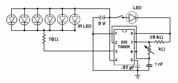
Figure 4. LM555 pinout, oscillator in astable mode and our emitter circuit
The frequency of oscillation f and the duty cycle D are given by:

With the values of R = 20k and C = 1nF we used and a 10k trimpot, the frequency of our square wave can be set in the range 36kHz < f < 72kHz. Setting the potentiometer to about 8.9kΩ, we get f = 38kHz, and D = 0.24. We also added a switch, a red LED which illuminates when the switch is closed to indicate current flow and proper operation of the circuit.
We were happy to see that the circuit worked as desired the first
time we tried it. Then we tested different ways of connecting the IR LEDs and
tried different resistances to drive them. All the 6 IR LEDs are connected in
parallel for optimum radiation power. However, in the end, we realized that the
IR receivers made directional did not detect the emitter as far as expected.
This is because not enough current was drawn to flow into the 6 LEDs in
parallel. We thought about improving the circuit by connecting the LM555 output
to a TIP31 (npn transistor) through a 5V voltage regulator LM340T5. This way the
6 IR LEDs would draw current directly from the battery (which would thus shorten
the battery life though). However, we were unable to finish testing our new
circuit and stuck with our original design.
The IR receiver:
We tested a couple different IR receivers, and the best we found was a TSOP41 38kHz receiver module from Vishay (although this was a sample part). The module is shown along with its internal block diagram in figure 4 and the circuit we used it in.
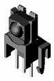

Figure 5. TSOP41 Reciever, block diagram, and test circuit.
Because the receiver detected signals coming from a 60° angle, we attached a white straw covered with black electrical tape on top of the sensitive area to make it directional. Since the outputs of the modules are either 0 or 1, we could connect them to any port on the microcontroller and read them simultaneously. However, when testing the system with a phototransistor (with analog ouput), we had to use the ADC in port A and perform the A/D conversion for each sensor one at a time, which is another reason why we abandoned phototransistors in favor of these “digital” receivers. This allowed us to avoid using the ADC which helped avoid timing issues given that we extensively use the NTSC code and there is limited time there to handle location, tracking, and displaying of the beacon.
Stepper Motors:
We used two bipolar stepper motors to control the rotation of the IR receivers in our radar system. The receivers were mounted on the motors which were then rotated in a “sweeping” pattern around the system space to determine the location and path of the emitter object. We started out building our radar system using the simple unipolar motors available in the lab before we received our bipolar motors from Jameco.
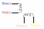
Figure 6. Bipolar Motor Coil schematic
The coils are hooked up as shown above in Figure 6. Bipolar motors lack the center taps present in unipolar motors and as a result they require more complex drive circuitry to reverse the polarity of each coil pair. We used the FAN8200 stepping motor driver shown below in Figure 8:
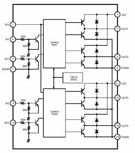
Figure 7. FAN 8200 Schematic used to control our bipolar stepping motors
Vcc and SGND were connected to MCU power and GND respectively. VSx and PGND pins were connected to 12V DC power and GND. We tied the enables to power to simplify our breadboard circuitry. We used IN1 to control the first coil pair (blue/red) by connecting blue to OUT1 and red to OUT2. Similarly we used IN2 to control the second coil pair (yellow/white) by connecting OUT3 to yellow and white to OUT4. We used Table 1 below to drive the motor to the right and left:
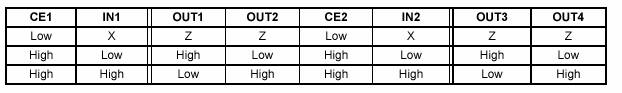
Table 1. Input Sequence to FAN8200 Circuitry
|
Step |
Blue (OUT1) |
Red (OUT2) |
White (OUT4) |
Yellow (OUT3) |
|
0 |
- |
+ |
+ |
- |
|
1 |
+ |
- |
+ |
- |
|
2 |
+ |
- |
- |
+ |
|
3 |
- |
+ |
- |
+ |
|
4 |
- |
+ |
+ |
- |
Table 2. Excitation sequence for our bipolar motors for 1 rotation CCW.
Since we used 2 bipolar motors, we needed two FAN8200 control circuits. We needed to specify the inputs (IN1 and IN2) on each FAN8200 in order to achieve the correct excitation sequence shown above in Table 2. We hooked up Motor2’s control inputs IN1 and IN2 to PORTB.7 and PORTB.6, similarly, we connected Motor 1’s control inputs IN1 and IN2 to PORTB.5 and PORTB.4; this allowed us to write the following sequence to PORT B.7 and PORTB.6: 11, 01, 00, 10, 11 in order to get Motor 2 to turn 1 turn (1.8 degrees) to the right. By writing this sequence of bits to PORTB.7 and PORTB.6, the FAN8200 then supplies the correct outputs to OUT1 – OUT4 in order to get the motor to turn precisely.
The FAN8200
simplified our circuitry because it includes all the control logic and H-bridge
circuitry built in. Bipolar motors require an H-bridge control circuit for each
coil which allows the polarity of the power applied to each end of the coil to
be controlled independently.
Similar to Lab 5, the MCU ports need to be protected from voltage
spikes caused by turning off power to the motor. This protection is built into
the FAN8200 through the use of diodes. Furthermore, the FAN8200 control logic
prevents us from shorting the power supply by ensuring that diagonally opposite
switches are closed as shown in Figure 8 below where in forward mode, switches A
and D are closed while in reverse operation, switches B and C are closed (Figure
taken from Reference 7)
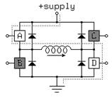
Figure 8. Simplifed H-bridge Schematic used in FAN8200 (control logic not
shown)
Although our motors supported ½ stepping operation, we did not feel a need to make use of such a feature given the limited scale our system is operating on. If we wished to expand our simulation to a bigger scale, such a feature will definitely provide greater accuracy in the triangulation calculations, but at the expense of a longer pulse sequence shown below in Figure 9.

Figure 9. Stepping Sequence for ½ step on our bipolar motors
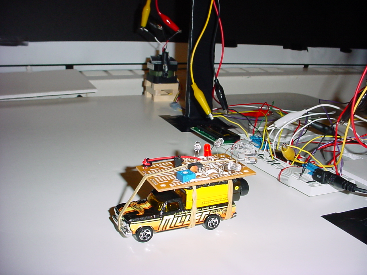
The receiver block:
To mount the IR receiver on top of the motor, we used fome core™ (foam board) because it is very light yet quite rigid, easy to cut, and cheap. We glued a fome core platform (covered with black tape) on top of the motor’s spinning rod. We then attached the IR module (with wire soldered on its pins) on top of it, adding cardboard for more stiffness. The tricky part was to connect the IR module to the microcontroller; simply connecting the wires form the modules to the board would make the wire twist when the motor would turn and pull it back, thus corrupting everything. So we designed a system that would allow the wires from the modules to turn around a group of 3 wires twisted together and connected to the microcontroller, while constantly making connection with only one wire. However, because the connection between the wire from the module and the wires to the CPU is not supposed to be tight (otherwise the wires would not revolve properly), it would sometimes fail to establish an electrical connection. So since we did not have the time and the means to improve it, we got rid of this design and simply used alligator clips. The wires connecting 2 clips are quite flexible enough, and we attached them to towers over the motors so as not to block the rotation of the motors.
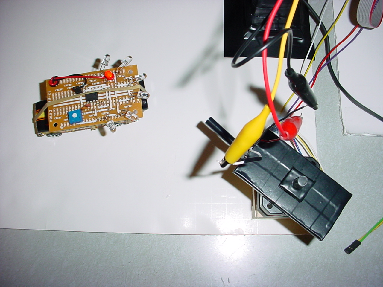
Figure 10. Diagram of IR Receiver Block construction
The motors were mounted on top of wooden pegs glued on a fome core board. The 2 motors were separated by 65 cm. The CPU consists of an Atmel Mega32 microcontroller on a STK500 board with pushbuttons and LEDs.
TV Screen/LCD output:
We used the TV to display the position of the beacon. The center of the TV screen represents the middle point between the 2 motors. There are 2 modes of operation: display only current location or display all previous positions (follow the trajectory). In the first mode, only one blinking point appears on the screen which shows where the beacon is relative to the monitor. In the second mode, we observe a trace of the motion of the beacon. We changed the TV code slightly to use PortD.7 to output the sync pulse and PortD.6 to output the video signal, this involved changing a few lines in the Lab 4 code given to us by Professor Land.
We also used the 16x2 LCD display available in the lab to display the distance of the beacon and the quadrant in which it is located (NE, NW, SE, SW). The LCD was connected to port C on the board. The switch buttons on the STK 500 board were also used. Buttons 0 is the on/off toggle and button 1 allows the user to switch between modes of display. The on toggle causes the motor to scan the area, find the initial max, and lock on to it. It then proceeds to track this max (the object) as best it can. If it loses the object it begins to search for it. The off toggle causes the motors to return to their initial state of operation. We used 2 LEDs on the STK 500 board. LED 1 is lit when the system is on, and LED 2 starts blinking when the beacon leaves a specified perimeter (alert).
Our software implementation broke down into the following areas: motor control, object tracking, display results. We first started by experimenting with the unipolar motors available in lab. We referenced two earlier 476 Projects (Ref 5, Ref 6) to see how students before us had written code to obtain a smooth, clean rotation of the motors. It was clear that we would need some sort of control circuitry to handle the pulses we sent. For the unipolar motors, this is achieve simply by using a ULN2003 wired as shown below in Figure 11:
Figure 11. Unipolar Motor Control Circuitry (Ref 5)
The unipolar motors differed in the sense that they had two brown wires to be connected to +12V DC and 4 colored wires corresponding to the two coil pairs while the bipolar motors have no such power wires. We noticed that both groups made use of a timer counter variable between successive pulse sequences sent to the motor. This is necessary because otherwise, the MCU will blast the sequences out at too fast a rate for the motor to process properly and turn accordingly. Using the unipolar motors, the max performance we achieved (without significant motor jitter) was by waiting approximately 1.95ms between writing successive pulse sequences to the MCU. By playing around with this timing counter, we were able to get the motor to turn at various speeds (increasing the interval between pulse sequences slows down the motors and decreasing the interval speeds up the motor). We decided against implementing variable speeds in our motor since we saw no advantage in doing so given our particular application. The unipolar test code we wrote gave us a good foundation to improve upon once our bipolar motors arrived. We simply changed the pulse sequences and port bits accordingly and achieved the same results with our new bipolar motors.
With the motor movement code written and debugged extensively, we were ready to move on to the next task- object tracking. As explained earlier, we used IR signals to track the location of an emitter object in our field of vision. We mounted the IR receivers on the two motors and by using the motors to scan the field, we simply wait for detection of the object before proceeding. The first thing we tried was to get the motors to do a complete sweep of the field and record where it detected the object. Then, we instructed the motor to return to this location and wait there. We were able to successfully accomplish this using the unipolar motors at first and then the bipolar motors as well. Since there is only one beacon to detect, there is no point in making a full rotation first; so we improved the algorithm by simply making the motors stop once a IR signal is detected, which saves time.
The next step was to track the object after initially finding it. We developed a seek algorithm that works in a simple manner where each motor seeks the object independently. Upon losing the object (no longer detecting signal at current location) we force that motor to scan the area in the vicinity of its last known location. We perform the search in a sweeping manner, increasing the search radius each time the sweep fails to find the object.
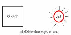
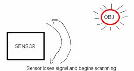
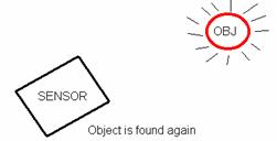
Figure 12. Demonstration of sweep performed by each IR receiver mounted motor
We included some optimizations to the
algorithm, by making some assumptions we feel are realistic and
justifiable. First, an object moving to the left will probably continue moving
in that direction. To take advantage of this, we store the direction each motor
had to turn last to find the object and our search begins by first going in that
direction until we hit our searchRadius limit and then we continue back in the
other direction. Secondly, we use a combination of while and if statements to
ensure that both motors track independently and are not dependent on the other
motor in any way whatsoever. We also assume that if a motor completes a 360
revolution and is unable to locate the object, then the object has left our
system’s range and the motor returns to its initial position.
The final step was to try and display the object’s movement on the
TV output with extra information displayed on the LCD display. This code was
based heavily on Professor Land’s video code given to us in Lab 4. We display an
initial circular ring showing the range of our radar system and one blinking dot
which is the fixed location of the sensors (midpoint). The moving object is
tracked and displayed through a series of video_pt statements. In software, we
have enabled two modes- tracking and current location. Tracking keeps the path
of the object displayed permanently on the screen while current location only
displays the current location of the object erasing the path of the object as it
moves across the screen. Once each motor has detected the objects location and
has stopped moving, the LCD displays the distance to the object from the center
(0,0) reference point and also displays the direction of the object in reference
to this center point (NE, NW, SE, SW).
We created a large state machine to be run within the LineCount == 231 part while the TV is not drawing anything. During this time, we scan the area for object, lock on to the object and track the object. During the tracking part, we output signals to the TV and LCD only if the object has moved and if both motors have successfully found it. This helped resolve some of the timing issues (jitter, etc) that we were seeing as we developed the code.
The motor control code was relatively straightforward. We had some bugs initially with our tracking algorithm, but we quickly resolved those. The code to display output to the LCD and TV was not complex as most of it was covered in earlier labs. However, the problems we ran into came when trying to connect all three pieces together. Individually, all three sections of the code perform as specified, but when combined into a single piece of software various bugs arise. For example, when tracking and displaying the object on the TV screen, sometimes the points flicker. In other cases, we saw that using the LCD was problematic in that it would not display correctly. We checked the hardware and ran the Lcdtest.c file which worked perfectly. We could not resolve this problem and shifted our work to try to display the distance and direction on the TV instead of the LCD. Overall our tracking system did not work as well as we expected (and hoped), because of all the sources of errors that we mentioned before and that we did not have time to eliminate. However, our expectations were very high, and our system was doing what it was supposed to do despite the limited amount of time and the cheap hardware we used, and we were satisfied with it .
things we tried which did not work:
Initially, we
dreamed of implementing a search and chase system that would track a foreign
object (which would be tagged with an IR beacon) and we would relay this
information to another designated object which would then seek out and make
contact with this foreign object. However, this proved too ambitious given the
timeframe and budget, so we did not pursue this idea. We also wanted to try and
use RF to transmit the IR receiver data to the MCU which would have simplified
the wiring in our circuit greatly, but this proved too complex to accomplish
within our timeframe.
speed of execution:
The
motors move fast and are able to keep up with a fairly fast moving object. In
fact, the data generated by the motor may be too fast for the TV to update
(which did cause some erroneous tracking output). We did not see any jitter or
flicker towards the end of our project after we decided not to use the LCD
display to output our results.
accuracy:
We fixed the
motors 65cm apart and they are able to track a given object up to 1m. It can
also track an object moving pretty fast provided it does not go back and forth.
The sources of inaccuracy in our system are the initial shaking produced by the
motors during the programming of the chip, the slight movement of the receiver
on top of the motor and the small length of the straw (to make the receiver
directional).
With all these parameters, and given the separation of the 2 motors and the angle between 2 steps for the motor (1.8º for a full step and 0.9º for a half step), the accuracy of the system is around a couple centimeters within a 1m radius. This inaccuracy increases as the object moves further away. To improve the accuracy of the location measurement, one could increase the distance between 2 receivers and/or get better stepper motors with smaller increments.
We also encountered some errors while testing of our design due to reflections on walls. Another source of error we encountered was due to the directivity of the LEDs. Our system produced some unexpected behaviors sometimes, when the LEDs were not aiming directly into the sensors. The IR receivers would be able to detect the incoming signal, but only when the motor is rotating, thus making the motor jerk going past the direction of the beacon then back and forth. Errors in the display of the location information come from timing issues in the code for the TV signal generation rather than hardware problems. We were unable to fix these bugs because they appeared randomly, and we suspect that they are due to the fact that so many different things are happening at the same time and very fast inside the code, thus probably interfering with TV signal generation.
how we enforced safety in the design:
We drew
power from the 5V supply provided by the MCU as well as a 9V supply to power the
motors. On our emitter object, we used a 9V batter to connect the IR LED
emitters. We do not believe our circuit poses a significant threat to any
intelligent user of our system. The wiring is neat and easily identifiable so
anybody with common sense can use our project without fear.
interference with other people's designs:
IR has a
limited range and high directivity; but even so, we made sure that no nearby
groups were transmitting or trying to receive while working on our
project. Beyond that, no other aspect of our project interfered with anyone
else’s work.
Infrared detection was not easy, because we can’t see infrared light so we can’t tell if a LED is emitting and there may be interfering sources such as daylight or emission from other equipment or reflections. Infrared tracking systems are not feasible in practice because it requires line of sight and because continuous tracking of emitters is not possible (a new search needs to be done once the target has moved).
If we had to redo our project, we would buy (no more sample parts) better IR receivers and mount them on the steppers motors (better ones too) more carefully for better accuracy. We would make a better emitter that radiates in every direction and strongly (another option than the one mentioned earlier would be to use a reflecting cone on top of an LED which disperses the emission of a single emitter). We would also make some changes to the search algorithm to make it more robust against potential sources of errors. Another element to consider would be the possibility of tracking several beacons.
Ethical Considerations:
1. to seek, accept, and offer honest criticism of technical work, to
acknowledge and correct errors, and to credit properly the contributions of
others
We have acknowledged all sources we used to complete this project in the
report as well as in the references section. We have credited the contributions
of all others whose work we used or referenced in any manner. We sought help
from Professor Land as well as the TA’s on numerous occasions and they were all
willing to help.
2. to avoid injuring others, their property, reputation, or employment by
false or malicious action
We made sure to obey all lab rules and safety precautions. We did not engage in
any false or malicious actions during the course of this project since we used
the lab in a safe and courteous manner.
3. to be honest
and realistic in stating claims or estimates based on available data
All claims made in this report are honest and are backed up with the
according data where available or pictures if applicable. We reported our data
in an objective manner and kept our project on a small, implementable scale in
order to be realistic and feasible.
4. to treat fairly all persons regardless of such factors as race, religion,
gender, disability, age, or national origin
We treated all
people we worked with on this lab fairly and we did not discriminate in any
manner whatsoever.
5. To assist colleagues and co-workers in their
professional development and to support them in following this code of ethics.
We helped other groups who worked on similar aspects of the project as us
like determining the pulse sequences for the motors or assisting in mounting
sensors appropriately to ensure a good quality signal is received each time.
Costs:
|
Qty |
Description |
Cost (total) |
|
2 |
Bipolar Stepper Motors |
9.90 |
|
2 |
FAN8200 |
1.70 |
|
2 |
LM555CN IC |
0.54 |
|
6 |
LVIR3333 |
2.34 |
|
1 |
Hot wheels Toy Car |
0.99 |
|
1 |
Mega32 / STK500 |
8.00 |
|
1 |
Glue Stick |
0.25 |
|
Large |
FomeCore (Foamboard) |
Free |
|
1 |
Breadboard |
2.50 |
|
1 |
Solderboard |
1.00 |
|
2 |
Vishay TSOP41 |
Free (samples) |
|
1 |
16x2 LCD |
5.00 |
|
Varies |
Resistors, Capacitors, Wires, Batteries, Tape, Straws, TV |
Free |
Total Cost: $32.22
Specific Tasks:
Arun- Software Implementation of
motor movement, object tracking, and tv/lcd display, debugging
Reda- Hardware design and implementation of receiver/emitters circuits, algorithm design, debugging
Acknowledgements:
We would like to thank Professor Land as well as our TA’s Dave and Jeannette for their help during the course of the semester and during our final project. Special thanks for keeping the lab open late and helping us out with the annoying bugs we found.
Schematics:
References:
1. Mega32 data sheet: http://instruct1.cit.cornell.edu/courses/ee476/AtmelStuff/full32.pdf
2. Bipolar Motor data sheet: http://www.jameco.com/Jameco/Products/ProdDS/163395.pdf
3. FAN8200 data sheet: http://www.jameco.com/Jameco/Products/ProdDS/241867FSC.pdf
4. LVIR3333 data sheet: http://www.jameco.com/Jameco/Products/ProdDS/106526.pdf
5. LMC555 data sheet: http://www.jameco.com/Jameco/Products/ProdDS/126797.pdf
4. Professor Land Video code: http://instruct1.cit.cornell.edu/courses/ee476/video/Video32v3.c
5. Vertical Plotter: http://instruct1.cit.cornell.edu/courses/ee476/FinalProjects/s2001/vp2/
6. RC NSX race car: http://instruct1.cit.cornell.edu/courses/ee476/FinalProjects/s2003/kw84/Report/documentation.htm