Introduction
The problem of encoding multiple input signals into a finite bandwidth space is one that is common in engineering problems today. It is found in communication system encoding schemes from cell phones to cable TV. The problem is that the system needs to carry several independent signals over a single communications medium. Some examples of data encoding for these data communication problems include time division multiplexing (i.e. telephone lines), code division multiplexing (cell phones), statistical multiplexing (internet), and frequency division multiplexing (cable TV).
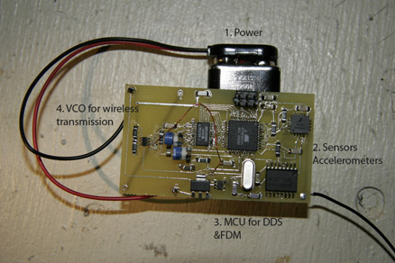
We have designed a wireless telemetry system that utilizes frequency division multiplexing (FDM) to encode several input sensor values onto a single analog channel for transmission. By using a single transmitter, we can simplify design and reduce bandwidth consumption and power costs. We have encoded three-axis accelerometer data using our technique. Direct digital synthesis (DDS) was utilized to convert three separate ten bit number intro three orthogonal frequencies. A linear combination of these orthogonal signals was FM modulated into the commercial FM band. We also have developed a decoding scheme which reconstructs the original input levels.
Back To Top
We decided that we wanted to use a commercially available FM demodulator (i.e. a walkman) to demodulate the wireless signal, so we knew we'd be limited to the range of human hearing for frequency encoding. We chose to fit our 3 accelerometer values into a 10kHz range. Each accelerometer analog level would be converted into a 10-bit number on the A/D port of the Atmel.
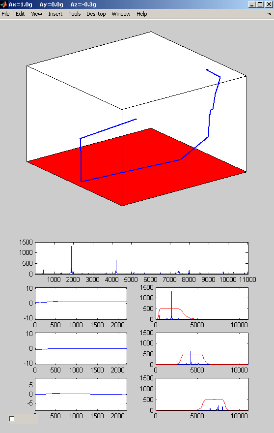
Once acquired, the data was band pass filtered using 3 separate 7th order butterworth filters. The butterworth filter bands were designed around our calculated values for frequency levels with some buffer outside of the band due to the steep edgets of the 7th order filter. The resulting three waveforms were the three pure FM tones encoding our acceleration levels.
These three single channel FM signals were passed into the fmdemod function in the MATLAB communications toolbox. The signal output was a level corresponding to the frequency of the signal at any point in time. From here, the 3-D acceleration value had been decoded and ANY kinetic metric could be calculated.
Section 15.239 Operation in the band 88 - 108 MHz.
(a) Emissions from the intentional radiator shall be confined within a band 200 kHz wide centered
on the operating frequency. The 200 kHz band shall lie wholly within the frequency range of 88-108
MHz.
(b) The field strength of any emissions within the permitted 200 kHz band shall not exceed 250
microvolts/meter at 3 meters. The emission limit in this paragraph is based on measurement
instrumentation employing an average detector. The provisions in Section 15.35 for limiting peak
emissions apply.
(c) The field strength of any emissions radiated on any frequency outside of the specified 200
kHz band shall not exceed the general radiated emission limits in Section 15.209.
91
(d) A custom built telemetry intentional radiator operating in the frequency band of 88-108 MHz
and used for experimentation by an educational institute need not be certified provided the device complies
with the standards in this Part and the educational institution notifies the Engineer in Charge of the local
FCC office, in writing, in advance of operation, providing the following information:
(1) The dates and places where the device will be operated;
(2) The purpose for which the device will be used;
(3) A description of the device, including the operating frequency, RF power output, and
antenna; and,
(4) A statement that the device complies with the technical provisions of this Part.
Part (a) is met by tuning of one of the potentiometers on the board itself.
The equipment involved in testing part (b) is prohibitively expensive for this project
Part (c) is met in accordance with part (a)
In accordance to FCC regulations, we would send a letter to the Engineer In Charge of the local FCC office if we wished to use our device for an extended period of time with a well coupled antennea. But due to poor radiation from a makeshift antennea, the device most likely falls below the requirements for part (b) of section 15.239. In most orientations of the antennea, the signal can not be detected at 2 feet, let alone 3 meters.
Though we didn't reach the particular application we specified (instrumented frisbee), all of the engineering subsytems for encoding, transmitting, receiving, and decoding are in place and working smoothly.
However, some of the IEEE code of ethics contents have been met in this project. Claims in this report are based on available data only and our comments are honest and appropriate references are sited. This report helps to improve the understanding of the relevant technologies involved. This project has advanced the technical competance of the members of the project. No one was discriminated against in the creation of our system. Injuries were avoided.
The following files are examples of what the output sounds like when the system is accelerated in each direction. Each of these audio files were created while oscillating the board back and forth in my hand.
| Component | Unit Price | Quantity |
| X-Y Axis Accelerometer +10g Freescale MMA6231Q | SAMPLE | |
| Z Axis Accelerometer +8g Freescale MMA1220D | SAMPLE | |
| Atmel MEGA32L | $8.28 | 1 |
| D/A convertor @3.3V and 10-bits | Sample | |
| Voltage Controlled oscillator with FM tuning pin Dallas Semiconductor MAX2606 | Sample | |
| Voltage Regulator Texas Instruments 3.3V regulator at 500mA | $0.22 | 1 |
| Voltage Regulator Texas Instruments 5V regulator at 50mA low dropout | $0.87 | 1 |
| 8 MHZ Crystal | $0.58 | 1 |
| Printed Circuit Board | Free space used on a board from an unrelated project | |
| Various resistors/capacitors/inductors and potentiometers | <$10.00 | |