Hardware Design
Overview
Our hardware design was
quite simple. It consisted of two KXM52
tri-axis accelerometers from Kionix, mounted on a custom proto-board, with long
wires connected to the prototype board designed for this course. Appendix B contains the full project
schematic.
KXM52 Accelerometer
The KXM52 is a
three-dimensional (tri-axis) accelerometer that measures accelerations in the
range of +/- 2g with a linear relation between acceleration and output voltage
of the chip. The chip is composed of
three differential-capacitive inertial sensors that have a linear relationship
with gravity. The sensor output is then
amplified with an output resistance of 32K [k1]. Thus, the output can be bandwidth-limited by placing a capacitor
to ground on the output. The functional
diagram is shown below in figure (7).
Figure (7): KXM52
Functional Diagram
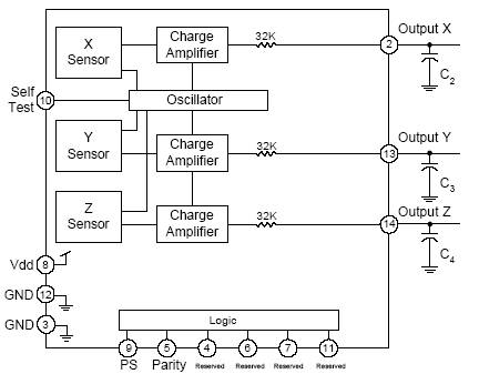
Power supply voltages can range
from 2.5 to 5.5 volts, so the Vcc rail (5V) on the prototype board was chosen
as the power supply voltage. The
bandwidth of the output signal is determined by equation (9) below,
Equation (9): Output Capacitance as a Function of
Bandwidth [k2]
![]()
Where
Ci is the ith output capacitance value. The bandwidth has an upper limit of 3KHz for
X and Y sensors and 1.5KHz for the Z sensor.
Shown below in figure (8)
is a typical application circuit.
Figure (8): KXM52 Application Circuit [k2]
A .1uF decoupling
capacitor is used between Vcc and ground [k2].
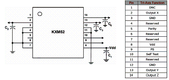
The KXM52 comes in a Dual
Flat No-lead (DFN) package, which is impossible to solder without highly
sophisticated and expensive soldering equipment. Luckily, a student sample kit is available for free, which
contains 2 stand-alone chips and 1 chip mounted onto a custom PCB board. We ordered several of these kits for free
and included the demo board for our application. The evaluation board is shown below in figure (9).
Figure (9): KXM52 Student Evaluation Board [k3]
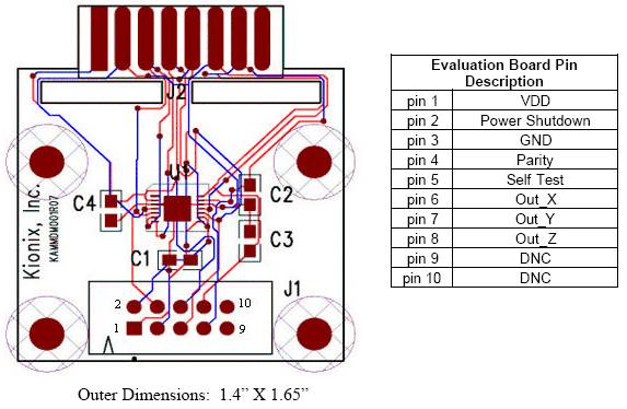
C1 through C4
are all chosen to be .1uF on the evaluation board, giving an effective
bandwidth of approximately 50 Hz on each channel. Thus, the system should accurately reconstruct “slow”
(human-speed) motions effectively.
We connected stranded wire
(for greater flexibility) to pins 1,3,6,7 and 8, which are in turn connected to
a pin header on the main prototype board.
Pin2 (power shutdown) was connected directly to Vcc to enable operation
at all times.
The KXM52 has a linear
output curve based on the measured acceleration. Equation (10)
demonstrates this relationship.
Equation (10): Voltage Output
As a Function of Acceleration [k2]
![]()
Notice that the zero-g point is centered at half of Vcc. Accelerations in either direction either low the voltage (to ground, indicating –2g) or raise the voltage (to Vcc, indicating +2g). The zero-g point has high stability, fluctuating within 5% for a reasonable temperature (-40 to 85 Celsius).
Human Interface
The KXM52 accelerometer is
very sensitive and can pick up small movements (shaking) of the chip if it is
not attached to a rigid body. Thus, to
ensure maximum accuracy and stability, the evaluation board must be attached
firmly to the human body. We used a
Velcro strap attached to the board to secure the board to the body. Also, the wires (stranded) that were
attached to the board were bundled together.
The wire-board junction was taped down using electrical tape. An accelerometer board is shown below in
figure (10).
Figure (10): Finished
Tracking Sensor

Another
concern of attaching the board directly to the body is safety. There are voltages on the chip, which may
come into contact with the body. We
have went through the precaution of isolating the wire connections from the
body by wrapping the connections in electrical tape. There is no concern of getting a shock from the evaluation board
itself.
For
best results, the tracking sensors should be placed on the top of the limb
(when the limb is only in the y-axis).
Prototype Board
We used the PCB board
designed by Professor Land to prototype this design. The RS-232 interface was installed along with a power on-off
switch. We used the Mega32 with a 16MHz
crystal and a diode attached to pin D.7 for visual feedback. Figure (11) shows our PCB board.
Figure (11): PCB
Prototype Board
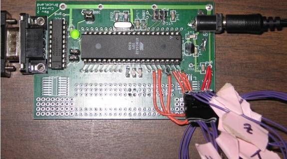
The Power switch is a
simple 3-pin switch, where in the left position it connects the left and center
pins together and in the right position, it connects the right and center pins
together. The left pin was removed and
the right and center pins were connected across the Vcc (Power) plug power pins. The result is no power to the system in the left position and
power on in the right position.
We created a custom header
for the KXM52 accelerometer boards. This
made prototyping much easier as a sensor had to only be plugged in, with no
worry of pulling out wires. The pinout
and header diagram are shown below in Figure (12).
Figure (12): Custom
KXM52 Accelerometer Header

Where pin1 faces the right
side of the board in Figure (11). Pin 1
is marked on both the board and the plug.
Two accelerometers are
used in this project. The connections
are shown below in Table (1).
Table (1): Accelerometer Connections
|
Pin # |
Connection |
to (point1) |
to (point2) |
|
1 |
Vcc |
Vcc |
Vcc |
|
2 |
Gnd |
Gnd |
Gnd |
|
3 |
Out_X |
A.0 |
A.3 |
|
4 |
Out_Y |
A.1 |
A.5 |
|
5 |
Out_Z |
A.2 |
A.6 |