Hardware Design
When we first came up with this project idea, we searched for capacitance sensor component, but they are all too expensive for this project. Thus we decided to put together our own capacitance sensor, using a relatively simple design that is fairly accurate for our purpose.
The whole idea about the capacitance sensor started when we found out that the voltage on the scope is different when we touch it compared to when nothing is connected. Therefore the circuit for this capacitance sensor is built from this primitive idea using an operational amplifier to amplify the resulting voltage due to the capacitance difference of our body and ground.
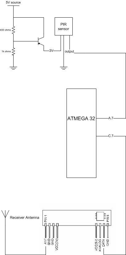
The circuits for the transmitter and receiver modules are shown here:
![]()
The circuit for the capacitance sensor is the at the top of the left diagram. We use a non-inverting op-amp with a gain of about 100. The touch wire acts as the sensor input and is hooked to the doorknob. It is connected to the positive input of the op-amp. Both inputs are grounded so that the capacitance difference can be sensed each time you touches the wire. This is done in order to saturate the voltage levels to produce a digital high or digital low. The voltage is fed into portA.7 of the MCU. We check the digital signal for a couple times long enough to make sure that the digital voltage level remains the same for a certain period so as to distinguish this touching signal (60Hz - low frequency) from the 433MHz high frequency RF signal.
For sensing an opening door, we used the accelerometer MMD1260D by Freescale Semiconductor. The voltage output of this accelerometer is fed to another channel of A/D converter in the MCU. This accelerometer is able to produce an output voltage that is linearly related to the acceleration within a certain range. But all we need to do is to detect fluctuations from a stable value to detect an opening door.
Pin C.0 is used as an output here to send data to the RF transmitter. We use a simple wire as the transmitter antenna.
For the receiver circuit, the Radiotronix RF receiver is used to receive the signals from the transmitter and they are fed into pin C.7 of the MCU. Another simple wire is used as the antenna.
The Passive Infra Red sensor is obtained from within a commercial product. Its working principle is that the higher the sensed temperature, the lower the output voltage from the PIR sensor. A few resistors and transistor are used to produce a 3V source to drive the PIR sensor and the output voltage from the PIR sensor is fed into pin A.7, an ADC channel of the MCU.
In addition, we also used a similar keypad obtained from the 476 lab, previously used in the lab assignments.
The keys and pins have the following configurations:
Pin 1  -- row 1 2 3 A
Pin 2  -- row 4 5 6 B
Pin 3  -- row 7 8 9 C
Pin 4  -- row * 0 # D

Pin 5  -- col 1 4 7 *
Pin 6  -- col 2 5 8 0
Pin 7  -- col 3 6 9 #
Pin 8  -- col A B C D

(a) Each switch shorts one row to one column.
(b) Each pin should be connected to one bit of an i/o port.
(c) The i/o port pins will be used both as inputs and outputs.
    When they are inputs, they should have active pullup resistors.
This keypad is connected to port B of the MCU at the receiver. This MCU is also
connected to the computer via UART serial connection.