

I. Introduction
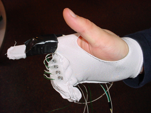
The Cornell University Airmouse Initiative is a motion sensing glove with buttons on it that plugs into your computer to function as a mouse.
Many tasks that are performed on the computer require the use of both a keyboard on the mouse, and many people find it frustrating and awkward to have to switch back and forth between them. So, we've created what we believe to be the solution to this dilemma, as you can wear the glove on your hand while you're typing and then when you want to move the mouse cursor, simply push a button that is already on your hand and point your finger at the screen and move it around. The Airmouse is comfortable to wear, and does not significantly inhibit typing. It functions completely as a two button serial mouse, and even implements variable rate vertical scrolling.
Back to TopII. High Level Design
Our project was inspired by two sources. Firstly, when Professor Land exclaimed, "I have free accelerometers, and they [can do cool things]," we felt as if we should explore the possibility of using them. We thought for a while about what kind of awe-inspiring device we could construct with acceleration sensors, and then we found our second fountain of inspiration - the mouse-glove that Tom Cruise used in Minority Report would not only be very neat were it real, and it was not impossible to make it real. Accelerometers seemed to be the ideal sensor for constructing a hand-mounted pointing device.
Our original plan used accelerometers to measure the acceleration of a user's hand and integrate that acceleration into a change in position. The math behind this is very easy - using Verlet Integration, we would approximate the integral of the acceleration to the second degree. Verlet integration interpolates between to measured accelerations, using the average slope between them to derive velocity. This is sometimes called "trapezoidal integraton." Here are the equations, courtesy of Professor Land's CS417 webpage:
This approach, however, turned out to be a practical impossibility. While we successfully implemented the Verlet scheme and watched a mouse cursor controlled by the scheme move on the screen as we expected it to, the glove had to be held exactly at 0g (or 1g for earth-normal) in all three directions. If gravity were allowed to affect the accelerometers at all, this acceleration added into the integral, and with no negative acceleration to remove it, the change in position that we calculated grew boundlessly. We needed gyroscopes to measure gravity so that we could remove its effect from our calculations, but gyroscopes are not inexpensive, and the cheapest ones cannot be soldered by human hands.
Because of this, we decided to construct a tilt mouse instead. While not as impressive as a position tracking device, the tilt mouse is easy to use (after a bit of practice) and almost as neat as a position tracking mouse. The math behind this scheme is very easy - measure the acceleration due to gravity on the mouse, and multiply this by some constant to scale your output to a desirable level. The Microsoft serial mouse protocol uses an 8-bit twos complement number scheme to send data to the computer, and the numbers outputted by the Atmel Mega32's analog-to-digital converter can be conveniently represented in the same number of bits. However, the numbers outputted by the accelerometer had to be altered to normalize voltage extremes to -128 and 127 and the accelerometer's neutral output to 0. We will discuss in the next section, Program/Hardware Design, exactly how this was done. In addition to scaling the output, we also used a step filter on the data to make the mouse easier to use. Our accelerometer was so sensitive that the slightest motion of one's hand would cause the device to output a nonzero acceleration. To give the user a more stable region around the zero point, we quantized all outputs below a certain level to 0, then normalized any outputs out of this cutoff range by the breadth of the cutoff range. For example, if the cutoff were abs(10), the intersection of all numbers > -10 and all numbers < 10 defined the cutoff region, and any outputs outside of this range would be normalized by +10 or -10, depending on whether the output were negative or positive, respectively.
In addition to position changes, mice detect button presses. We implemented 4 buttons in our mouse - output on/off, left click, right click, and scroll enable. Each pushbutton is connected to a port pin on our microcontroller. When the output on/off button is pressed, the serial mouse output to the computer is either [re]enabled or disabled. This allows the user to move his or her hand and not have the motion affect the mouse pointer. Left click functions as a mouse left click, right click functions as a mouse right click, and scroll enable disables all motion and other button outputs while it is held down, and the y-output of the accelerometer is translated into a scroll-wheel output to the computer.
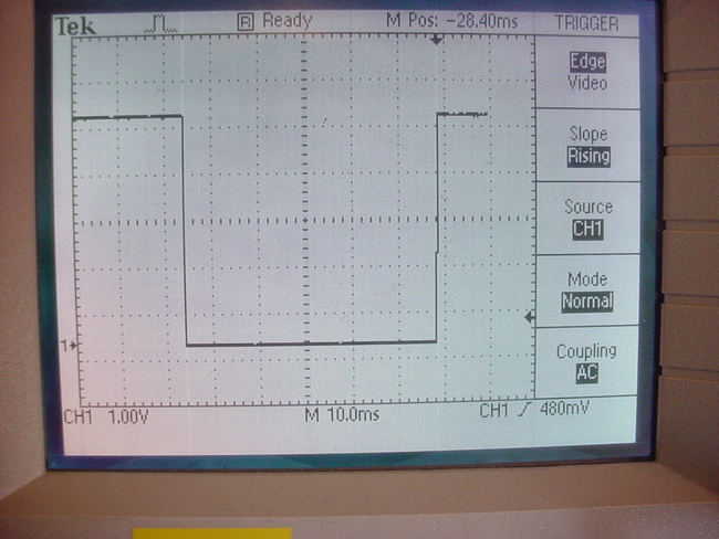
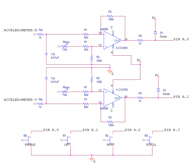
The only hardware/software tradeoff with which we had to deal was the sensitivity of our analog to digital converter (ADC). The granularity per "click" of the ADC is approximately 19.5mV/click. When we used accelerometers with sensitivities of approximately 50mV/g for our position mouse the outputs of the devices had to be normalized to the full ADC range of 0-5V so that we would have good sensitivity on our device. We will explain in the next section exactly how this was done. For our tilt mouse, we used accelerometers that outputted 1000mV/g, so the sensitivity was much higher, but we decided to normalize the range to 2000mV/g to gain even higher sensitivity, especially since we already had the necessary circuits designed and constructed. Another hardware/software issue one must usually take into consideration is the "bouncing," or inconsistent, state in which some pushbuttons can be after a transition, but our buttons were internally debounced, as can be seen in the below figure, so we did not have to worry about polling them at certain intervals.
Our design is related to two standards. We use the Microsoft serial mouse protocol and an RS232 serial connection. RS232 uses -+12V for high and low signals, respectively. RS232 idles at +12V. Our microcontroller outputs 5V high, 0V low serial (TTL level), so we had to use a serial level shifter chip to allow the microcontroller to properly speak with the computer. The Microsoft serial mouse protocol works as such: when the RTS line of the serial connection is pulled logic high then falls logic low again, the computer expects you to send an identifier string to it so that it can determine what type of device you are. The protocol expects data at 1200 baud, 8N1. Our controller sends it "MZ" for Microsoft serial scroll mouse. The computer may query you for this information multiple times, but after 5 or so times you can stop sending it the identifier code and it will still consider you to be identified. The packet format is as follows:
| Packet 0 | 1 | 1 | L | R | Y7 | Y6 | X7 | X6 |
| Packet 1 | 1 | 0 | X5 | X4 | X3 | X2 | X1 | X0 |
| Packet 2 | 1 | 0 | Y5 | Y4 | Y3 | Y2 | Y1 | Y0 |
| Packet 3 | 1 | 0 | 0 | M | Z3 | Z2 | Z1 | Z0 |
L, R, and M are the left, right, and middle mouse buttons. A 1 indicates pushed and a 0 not pushed. (most significant) Y7-Y0 (least significant) represents the twos complement mouse delta Y, with positive Y pointing to the bottom of the screen. X is the same format as Y, with positive X pointing to the right of the screen. Z is also in the same format as Y, with positive Z being scroll up. The first 1 bit in every packet is an extra stop bit. From what we've seen, some implementations set it 1, and some implementations set it low. We listened to the data coming off of a genuine Microsoft serial mouse, and it set the bit as 1, so we chose to set it as 1.
At http://patft.uspto.gov, we searched for "accelerometer AND mouse" and "mouse AND glove," and we found one invention very similar to our project. US patent #6,870,526 is a "Glove mouse with virtual tracking ball." It uses roll of the hand to measure direction of mouse traversal and bending sensors in the thumb and index finger apparatuses to determine whether the mouse will move in a negative or positive direction on the indicated line of orientation. This mouse functions differently than ours, as ours uses magnitude of roll and pitch to determine the direction and speed of the mouse motion. No mention of mouse click buttons was made in the description of this invention.
Back to TopIII. Program/Hardware Design
Here is a block diagram of our program:
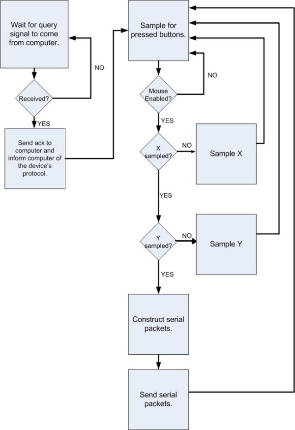
First we wait for the computer to toggle the RTS line. When it does, we send it "MZ," the indicator that we are a Microsoft serial scroll mouse. We respond to 5 queries, then disable query response and start mouse functioning.
After the mouse has started functioning, the buttons are sampled on every cycle. If the mouse is not enabled, the program cycles through the button sampling until the mouse is enabled. After the buttons are sampled and the mouse is enabled, a check is done to see which acceleration axes have been sampled. If X has not been sampled, set the sample multiplexer to Y, sleep until X is ready, and sample X. The multiplexer is set to Y before we sample X because the current sample being processed is always taken off of the current multiplexer value, which is X if X has not been sampled. If X has been sampled, we check to see if Y has been sampled. If it has not been, set the multiplexer to X, sleep until Y is ready, and sample Y. If Y has been sampled, modify the samples to the correct twos complement numbers, scale them, and create the serial packets. Send the serial packets, indicate that X needs to be sampled, and return to the beginning of the loop. The mouse is enabled and disabled by one of the sampled buttons. If the button value is read as "pressed" and its previous value was "not pressed," the mouse enable/disable is toggled.
The tricky parts of this program were the timing and the conversion of our accelerometer output to the proper twos complement number. We had some problems with our accelerometer readings - they became erratic on certain types of reads, specifically when we moved the mouse on the NW-SE plane. We could not figure out how to get steady readings until we googled our problem and found a page put up by previous ECE476 students. These students (credited in our conclusion) built a mouse similar to ours, and to get good readings they slept their microprocessor until the reading was ready. We simply added sleeps before we read our values, and the entire setup worked as we expected it to. As for our number formatting, when we formatted the numbers by performing mathematical operations on them, we found that our math often caused unexpected overflows. These overflows, coupled with the fact that we could never tell if we were casting the numbers properly, prompted us to devise an almost purely bit-manipulative method of converting our accelerometer outputs to numbers that we could send to the computer. Please see our commented code in the Appendix for a detailed description of our number conversion process.
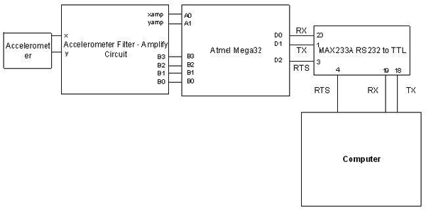
The hardware for our project is centered on information gathering and processing. Our accelerometer output goes through 3 stages. The first stage is a lowpass filter that removes the high frequency noise from the accelerometer. The second stage is a differential amplifier stage. The differential stage amplifies the signal by a factor of 2 - this expands the accelerometer output from 1.5V to 3.5V for -1g to 1g to 0.5V to 4.5V. Introducing gain into the accelerometer output allows us to get higher resolution with the ADC because the signal almost fills the 0-5V range of the ADC instead of only filling 2/5 of it. The negative end of the differential input is the accelerometer output. The positive end of the differential input is the output of a potentiometer whose inputs are attached to 5V and 0V. This potentiometer allows us to tune the accelerometer 0g level to a voltage of our choice. The final stage is a protection stage for the ADC. Since the output level of the amplifier is not rail-to-rail with its power supply, we had to use a power supply that could produce outputs potentially damaging to the ADC. The output of the amplifier goes through a resistor, then through a diode to 5V. The output is taken off of the junction between the resistor and the diode. This prevents the output of the amplifier from getting higher than 5V+the internal voltage drop of the diode (which is about 0.67V). In addition to the two accelerometer inputs to our microcontroller, we poll 4 pushbuttons, which provide enable/disable functionality, left click, right click, and mouse scrolling. These pushbuttons are tied to microcontroller pins and ground. The pins are internally pulled up, so the buttons are active low - pushing the button ties the pin to ground. Please see our schematics in the Appendix for more detail.
As was mentioned before, we altered our design slightly from our original idea. Our first design integrated our measured accelerations to translate the lateral movement of the mouse into a position change. Since we could not remove the effects of gravity from our integration, it was extremely prone to error, since any roll or pitch on the device introduced unwanted acceleration to the device. Therefore, we decided to base our motion on the very thing that made our first design improbable - the roll and pitch of the device. Rolling the device counterclockwise moves the mouse to the left, while rolling it clockwise moves the mouse to the right. Pitching the device towards you moves the mouse down, and pitching it away from you moves the mouse up. The vertical motion of the mouse is reversed, much like a joystick in a flight game. We found that this type of motion is easier to adapt to than having the pitch noninverted.
Back to TopIV. Results
As was mentioned before, we altered our design slightly from our original idea. Our first design integrated our measured accelerations to translate the lateral movement of the mouse into a position change. Since we could not remove the effects of gravity from our integration, it was extremely prone to error, since any roll or pitch on the device introduced unwanted acceleration to the device. Therefore, we decided to base our motion on the very thing that made our first design improbable - the roll and pitch of the device. Rolling the device counterclockwise moves the mouse to the left, while rolling it clockwise moves the mouse to the right. Pitching the device towards you moves the mouse down, and pitching it away from you moves the mouse up. The vertical motion of the mouse is reversed, much like a joystick in a flight game. We found that this type of motion is easier to adapt to than having the pitch noninverted.
Back to TopV. Conclusions
Analyse your design in terms of how the results met your expectations. What might you do differently next time?
The results of our project somewhat met our expectations. In the initial idea and design phase, we had planned to make the mouse detect and position using absolute position of the hand, but we quickly discovered that this was impossible without using a gyro to provide a reference for the angle of Earth's gravitational force. However, after we modified our design to simply use the tilt of the hand to produce a cursor velocity, we did not have any problems whatsoever in achieving our expectations in our results. In future versions of this project, we would investigate an inexpensive gyro so that we would be able to account for gravity in the motion sensing, therefore allowing us to obtain absolute position of the device in free space.
Intellectual property considerations.
Did you reuse code or someone else's design?
Although we thought up our original design independently of influence from any other ECE 476 students, after beginning our project we discovered that a group from 2002, Christopher Kung and Peter Wang, had done a similar project. All of our design ideas and code was completely our own, however we did implement one feature because of something we saw in this previous group's code. We noticed that in order to read the ADC correctly at the speed we needed to do so, they had to sleep the processor at a certain point in the code (see code for details). When we were having problems with our ADC, we tried doing this as well, and it solved our problems. The group's website that we accessed is as follows:
http://instruct1.cit.cornell.edu/courses/ee476/FinalProjects/s2002/pw33/ece476finalweb.htm
Did you use code in the public domain?
We did not use any code that was in public domain, but we did research the Microsoft serial mouse driver. Although our resources did not contain actual code, they gave a very complete specification of the details of the protocol that we then produced our own code to operate. The website that we referred to for this information on the Microsoft serial mouse driver is as follows:
http://freedos-32.sourceforge.net/showdoc.php?page=sermouse
Are you reverse-engineering a design? How did you deal with patent/trademark issues.
We did not reverse-engineer anything in order to create our Airmouse, and as far as we know the Microsoft serial mouse protocol we used it openly published, so we do not believe that someone else reverse engineered it either. There were no patent or trademark issues for us to deal with, as far as we could find.
Did you have to sign non-disclosure to get a sample part?
We did not have to sign any non-disclosures to get sample parts. We simply went to the company's websites (see Vendor Sites in Appendix) and gave them our information and they sent us the parts we requested to sample.
Are there patent opportunites for your project?
We feel that there are patent opportunities for our project. When we looked for patents on similar devices, we found only one, but it was still fundamentally different in design than our device as we described in the High Level Design section. Of course, if we were to go commercial with this product, there would need to be multiple sizes, as people's hands vary greatly in size.
Ethical Considerations
Our Airmouse project adheres to all of the relevant parts of the IEEE Code of Ethics. The following is an explanation of how it adheres to each relevant point.
To be honest and realistic in stating claims or estimates based on available data.
The claims that we have made our Airmouse can do, both on this website and also in any other forms of communication regarding our project, are 100% true and accurate to the best of our knowledge.
To improve the understanding of technology, its appropriate application, and potential consequences.
The goal of our project is to further our own understanding of the technologies used within this project, and also to expose others to the opportunities that technology provides as applied to modern day personal computing.
To maintain and improve our technical competence and to undertake technological tasks for others only if qualified by training or experience, or after full disclosure of pertinent limitations.
Throughout the design and implementation of this project, both my partner's and my technical competence improved vastly as we learned how to operate the involved devices and technologies to our own specification. As we learned nearly all we needed to know to complete the task in ECE 476, both of us were fully competent to handle any of the tasks we accomplished during implementation of the project.
To seek, accept, and offer honest criticism of technical work, to acknowledge and correct errors, and to credit properly the contributions of others.
The majority of the criticism we sought or accepted was from the course staff, primarily Professor Land, Ethan, John, Chethan, and Dan. Most of the ideas in our project were our own, with exception to a small bug fix in the code, which we credited in the Intellectual Property Considerations section to Christopher Kung and Peter Wang.
To treat fairly all persons regardless of such factors as race, religion, gender, disability, age, or national origin.
Both members of this project were of the same race, religion, gender, age, and national origin. Further, there were no significant disabilities present between the members. Therefore, there was fair treatment of all persons, regardless of any other inherent differences among the members of the group.
Legal Considerations
As RF transmitters were not used in this project, and there were no devices that are detectable outside the physical space of the project, there were no legal considerations that we needed to adhere to.
VI. Appendix
#include <Mega32.h>
#include <delay.h>
#include <string.h>
#include <stdlib.h>
#include <stdio.h>
#define CUTOFF 1 //define radius of cutoff region around 0
int extint; //keeps track of
number of external interrupts
char send_message[12]; //message to send
over serial
unsigned char
message_pos; //message cursor
int connected, enabled; //keeps track of the connected/disconnected
//and enabled/disabled states of the device
unsigned int ms_timebase; //milliseconds
unsigned int keypress_timebase; //time for keypresses and buttons
unsigned char
accel, x1, y1, scroll; //data read and
processed from ADC
unsigned char
admuxnum; //specifies which pin to read the ADC from
unsigned char
pushed[4], prevpush[4], button[4]; //button debouncing variables
unsigned char
i; //used for button reading loops
interrupt [EXT_INT0] void RTS(void){
extint++;
if(extint>1){ //wait until after first external interrupt
message_pos= 0;
send_message[0]= 'M'; //tell Windows we're a serial scroll mouse
send_message[1]= 'Z';
send_message[2]= 0;
UCSRB.5= 1;
PORTD.7= 1;
connected= 1; //we're connected
enabled= 1; //device is enabled
if(extint>5) {
GICR= 0; //after we've been recognized, stop telling Windows what we
are
}
}
interrupt [USART_DRE] void send(void){
if(send_message[message_pos]==0){ //if no more message, stop sending
UCSRB.5= 0;
}
else{
UDR= send_message[message_pos];
//otherwise keep sending message
message_pos++;
}
}
interrupt [ADC_INT] void readADC(void){
accel=
ADCH; //read
acceleration from ADC and store into accel
}
void initialize(){ //initialize all
the variables
UCSRB= 0x18; //enable
TX
UBRRH= 0b00000011; //1200
baud
UBRRL= 0b01000000; //setting
up serial
DDRD= 0xFA; //set
up port D
PORTD.7= 0; //turn on LED
DDRB= 0x00; //set up port B
PORTB= 0xFF;
extint=
0; //start at
first external interrupt
MCUCR= 0b10010010; //set mcu to interrupt on any
change in serial line
GICR= 0x40; //enable external interrupts
admuxnum=
0; //read
x-axis first
x1= 0; //0 x-coords
y1= 0; //0 y-coords
accel=
0; //0
acceleration
ADMUX= 0b01100000; //read x-axis first
ADCSR= 0b11101111; //adc status
connected= 0; //device is not
connected
enabled= 0; //device is
disabled
for(i=0; i<4; i++){ //reset all button
pushes
prevpush[i]= 1;
pushed[i]= 1;
button[i]= 0;
}
memset(send_message, 0, 12); //allocate memory
for serial comm
message_pos= 0; //set message cursor at beginning
#asm("sei"); //enable interrupts
}
void main(void){
initialize(); //initialize
variables used
while(1){ //never stop
running
if(connected==1){ //if device is
connected
for(i=0; i<4;i++){ //detect any buttons pressed
pushed[i]= (PINB>>i) & 0x01;
if(prevpush[i]==
pushed[i]){
button[i]= (~pushed[i]) & 0x01; //make sure they're
pressed
}
}
if(prevpush[0]==1
&& pushed[0]==0){ //if it was the enable button
enabled=
enabled ^ 0x01; //then
toggle enable/disable status of device
}
for(i=0; i<4;i++){ //otherwise store the button push
prevpush[i]= pushed[i];
}
if(admuxnum==0){ //if set to read
x-axis acceleration
ADMUX= 0b01100001; //setup the ADC pin
#asm("sleep"); //sleep processor to help sync up ADC reads
x1= accel; //read ADC
admuxnum++; //switch to read
y-axis
}
else{
ADMUX=0b01100000; //reading y-axis
#asm("sleep"); //sleep processor to help sync up ADC reads
y1= accel; //read ADC
admuxnum=
0; //switch
back to read x-axis again
if(x1==0) x1= 127; //re-scale x-axis to be inverted
else{
if(x1>128){ //this if-else
reverses the two halves of the x-scale
x1-=128;
/*x1= ~x1; //this code flips
the x-axis
x1+=1;*/
}
else{
x1+=128;
/*x1= ~x1; //this code flips
the x-axis
x1+=1;*/
}
}
if(y1>128){ //this if-else inverts the y-scale
y1-=128;
/* y1= ~y1; //this code flips the y-axis
y1+=1;*/
}
else{
y1= (y1 ^ 0x80);
/* y1= ~y1; //this code flips the y-axis
y1+=1;*/
}
memcpy(&scroll, &y1, 1);
//copy the value of y1 into scroll
scroll= (scroll
& 0x07) | ((y1>>4) & 0x08);
//scale down scroll speed
y1 = (signed
char)((signed char)y1>>2); //scale down mouse
speed in y-axis
x1 = (signed char)((signed char)x1>>2); //scale down mouse
speed in x-axis
//if x value is
in the cutoff range, make it zero
if(((signed char)x1) < CUTOFF && ((signed char)x1) >
-CUTOFF) x1=0;
//normalize
any other values to respect cutoff range
if(((signed char)x1) >= CUTOFF) x1= ((signed
char)((signed char)x1) - CUTOFF);
if(((signed char)x1) <= -CUTOFF) x1= ((signed char)((signed char)x1) +
CUTOFF);
//if y
value is in cutoff range, make it zero
if(((signed char)y1) < CUTOFF && ((signed char)y1) >
-CUTOFF) y1=0;
//normalize
any other values to respect cutoff range
if(((signed char)y1) >= CUTOFF) y1= ((signed
char)((signed char)y1) - CUTOFF);
if(((signed char)y1) <= -CUTOFF) y1= ((signed char)((signed char)y1) +
CUTOFF);
PORTD.7= button[3]
& 0x01; //set
LED to button 3
if(enabled==1){ //if the mouse status is enabled
if(button[3]==0){ //if not scrolling
//assemble
motion packets
send_message[0]= 0xC0 | ((button[1]<<5) & 0x20) |
((button[2]<<4) & 0x10)
|((y1>>4)&
0x0C) | ((x1>>6)& 0x03);
send_message[1]= 0x80 | (x1 &
0x3F);
send_message[2]= 0x80 | (y1 &
0x3F);
send_message[3]= 0x80;
}
if(button[3]==1){ //if scrolling
send_message[0]= 0xC0; //assemble
scrolling packets
send_message[1]= 0x80;
send_message[2]= 0x80;
send_message[3]= 0x80 | ((scroll)
& 0x0F);
}
send_message[4]= 0; //end transmission
message_pos= 0; //reset message cursor
UCSRB.5= 1; //send the message through the serial interface
while(UCSRB.5==1){} //until the message is done sending
}
}
}
}
}
| Part Num. | Description | Qty. | Unit Price |
|---|---|---|---|
| ATMega32 | Atmel microcontroller | 1 | $8.00 |
| --- | White board | 1 | $6.00 |
| --- | 9V DC Power supply | 1 | $5.00 |
| AMP0452 | DB-9 connector for serial port | 1 | $2.00 |
| MAX233A | TTL to RS232 convertor | 1 | $0.00 (sampled) |
| --- | Custom PC board | 1 | $5.00 |
| LM358P | Op amp DIP | 1 | $0.45 |
| --- | Trim potentiometers from lab | 2 | $0.50 |
| --- | 100K resistor | 4 | $0.00 |
| --- | 50K resistor | 4 | $0.00 |
| --- | 1K resistor | 4 | $0.00 |
| --- | 0.01uF capacitor | 2 | $0.00 |
| --- | Diode | 2 | $0.00 |
| KST221G | Push button | 6 | $0.40 |
| UA78M33CKC | 3.3V fixed voltage regulators | 2 | $0.56 |
| ADXL203 | Analog Devices Accelerometer | 1 | $0.00 (sampled) |
| --- | Pair of girly prom gloves | 1 | $8.00 |
| --- | Old unmated sock | 1 | $0.00 (from Joe's sock drawer) |
| ***Never Received 2x RC4136N Quad Op-Amp, Were Told to Use LM358P Instead | |||
| Total: | $38.97 | ||
Research Microsoft serial mouse protocol: Joe
Construction of custom PC board: Andrew
Sampling of parts: Joe
Construction of project-specific circuits: Andrew and Joe
Testing: Andrew and Joe
Initial structure of code: Andrew and Joe
Mouse Protocol code: Joe
Accelerometer output processing: Andrew and Joe
Final website report: Andrew and Joe
Photography: Bruce Land Back to Top
VII. References
http://www.atmel.com/dyn/resources/prod_documents/doc2503.pdf
http://rocky.digikey.com/WebLib/Maxim/Web%20Data/MAX220%20thru%20MAX249.pdf
http://rocky.digikey.com/WebLib/Texas%20Instruments/Web%20data/LM158(A),%20LM258(A),%20LM358(A),%20LM2904(Q).pdf
http://www.analog.com/UploadedFiles/Data_Sheets/279349530ADXL103_203_0.pdf
http://seth.positivism.org/man.cgi/4/mouse
http://users.tkk.fi/~then/mytexts/mouse.html
http://freedos-32.sourceforge.net/showdoc.php?page=sermouse
Back to Top