Hardware
Television
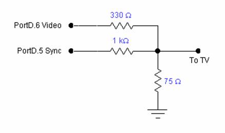
A digital to analog converter was needed to produce the video signal for the television. The circuit used was the same circuit as used in the Lunar Lander lab. The resistors produce the appropriate voltages for sync pulses and white and black colors on the television. The circuit diagram below was taken from the lab handout online.
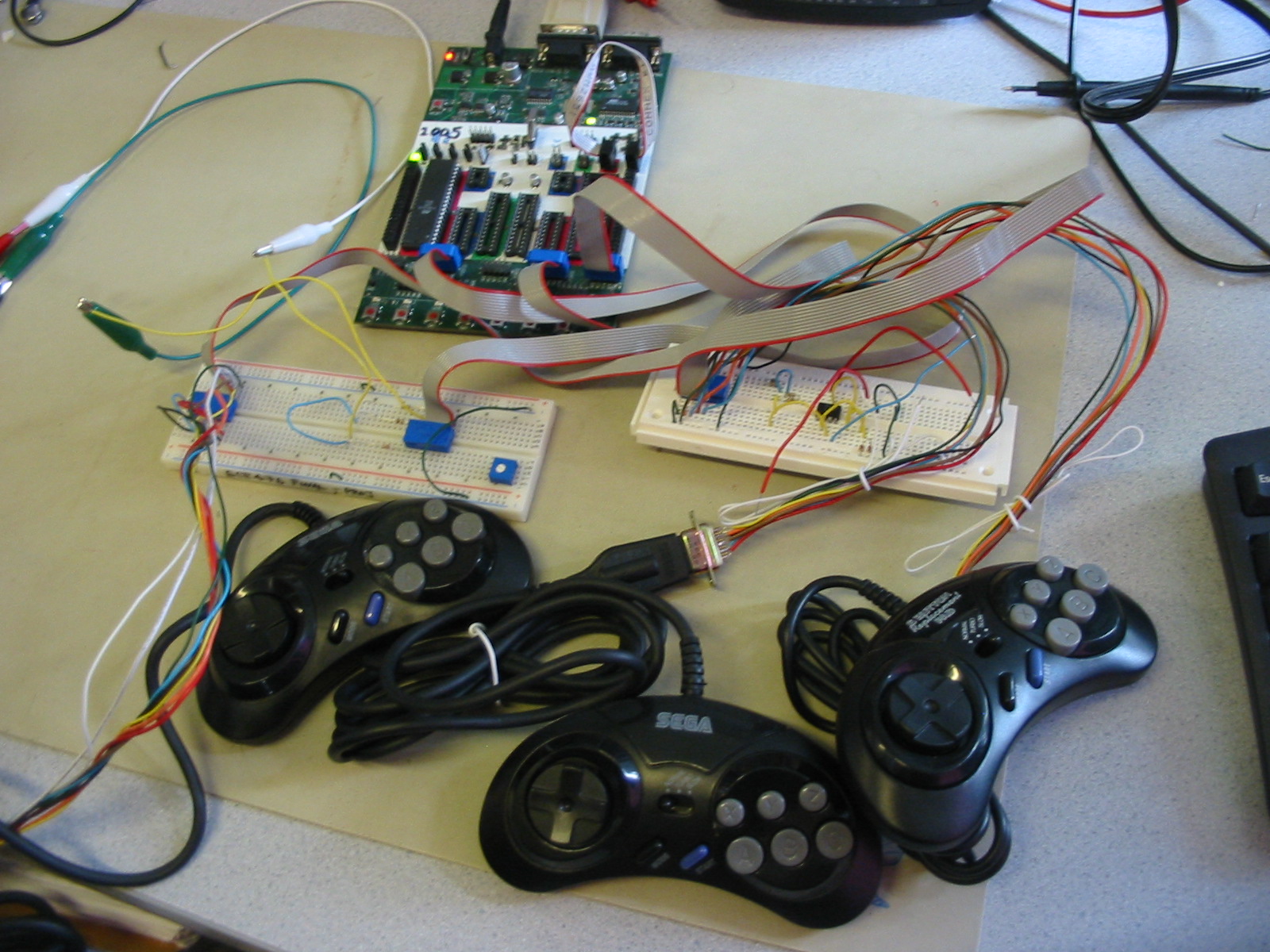
Sega Genesis Controllers
The controllers have 6 outputs and 3 inputs. The 3 inputs are used for the power, ground and select signals. By setting the select signal high or low, the 6 outputs correspond to different buttons on the controller. Since we only needed the direction pad (4 outputs) and the B and C buttons (2 outputs), we could keep the select line at a constant high, even though there are more than 8 buttons.
To support the multiplayer version, we interfaced 3 controllers with our MCU. The Digger controller was used to select the mode of play. Hence, it required the B and C buttons in addition to the direction pad. The 2 Nobbin controllers require only the direction pads. Therefore, the 2 Nobbin controllers could share one port (C), while the Digger controller required its own port (B).
Things We Tried That Did Not Work
Galvanic Skin Response Sensor (GSR)
A GSR works by measuring changes in the skin’s resistance as the anxiety levels of the person wearing it changes (due to increased sweat gland activity). We tried to construct the GSR for the player controlling the Digger. If the player was more anxious, we planned to slow the Digger down, or cause some other detrimental effect to further increase the player’s anxiety.
Our reason for implementing this was to add another level of hardware complexity to the project, and to make it even more fun to play. Unfortunately, the readings provided by the GSR sensor did not seem to vary at all, after an initial settling period, even when we wet our fingers and played the game.
We have included a schematic of the circuit we constructed below. There is no guarantee that this circuit is actually correct. Unfortunately, we had only one day to implement the circuit due to time constraints, and that day happened to be a Sunday. Hence, we did not have the opportunity to seek Professor Land’s help with our circuit.

Galvanic Skin Response Circuit
The body is placed in series with the some resistance by connecting the positive terminal of the battery to one finger and one end of the potentiometer to a different finger. This connection can be achieved by taping the wires to aluminum foil and wrapping the foil around each finger. Then, a voltage divider is formed and as the body’s resistance varies, the voltage fed into the op-amp varies.
The op-amp acts as a voltage follower to isolate the LED in the 4N35 package from the GSR, so as to not affect the GSR reading as its own resistance changes. The changing output voltage of the op-amp varies the intensity of the LED, and hence the base current of the 4N35 transistor. This translates into a changing emitter current through the emitter resistor that is roughly related to the base current by beta. The voltage across the emitter can be read into the MCU, run through the ADC and used in the program.
The 1 MΩ resistance in the voltage divider and 3 V battery ensure that the voltage across the LED is slightly over 1 V, as deduced from the data sheet graphs. The potentiometer is there to compensate for different baseline skin resistance between people. Also, the 75 Ω resistor to ground ensures that the current through the LED is no greater than 20 mA. The emitter resistor is chosen to provide a suitable input voltage to the ADC. Finally, the 4N35 package was used to opto-isolate the GSR user from the 110 V power supply.