The purpose of this Vocal Trainer, designed by Anderson Lin and Jerry Chiang, is to train people in singing accurate pitches, and ultimately become a vocal expert. Also, the vocal trainer has other features such as tuning, in which it can be used as a tuning machine for musical instruments. The Vocal Trainer, when used in Karaoke mode, can detect the fundamental frequency that the user sings, with customizable beat rate, while giving feedback to the user; therefore allowing the user to adjust his or her singing pitches, improving his or her singing accuracy.
Our motivations for this project come from a couple things. For Anderson, one of the motivations for the Vocal Trainer comes from the increasingly popular Karaoke. While there are many Karaoke system out in the market, very few offer a scoring system, in which the singer can get feedback on how well he or she sings. The ultimate goal for the Vocal Trainer, therefore, is to make that a reality. This will not only motivate people to improve their singing, but also act as a game similar to that of Dance Dance Revolution, known as the DDR. With its embedded functionality, it makes sense for the Vocal Trainer to come with the feature of tuning for musical instruments. These two functions are both very practical in reality.
For Jerry, the strongest motivating factor has been a more personal need for such a device. Being a composer, he often finds that, though he has tunes in his head which he can readily express by singing or humming, he is unable to record those tunes accurately by hand. With a device that has the ability to match input frequencies to the nearest musical pitch, there is hope for an easy way to transcribe these melodies. And so for him, the vocal trainer has a very practical and direct application.
In designing the Vocal Trainer, we want to be able to take in human voice or instrument tones using a microphone, then filter and amplify the input signal to attain the desired voltage level, and base on this voltage level, we can generate a clock signal like square wave, via Schmitt Trigger, with the fundamental frequency of the input signal. After generating the square wave, we will feed it into Mega32 as an external interrupt, triggered at the rising edge. And using comparison with respect to the internal crystal clock, where the frequency is known, we will be able to calculate the fundamental frequency. However, this can only be accomplished with a well processed signal in order to obtain a stable and accurate result.
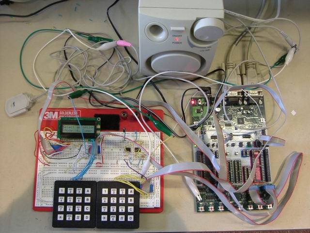
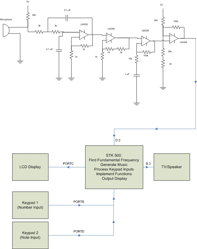
In implementing the user interface of the Vocal Trainer, we want to make the matter as simple as possible due to limited time alloted for the project. Another reason for it is that we want to implement many features in our menu, and that our primary focus is to obtain the most accurate results possible. As a result, we choose the 2-line LCD as our display, and 2 keypads as our menu input devices. Also, for optimum efficiency, we want the hardware to take care of most of the signal processing, with the software dedicated mostly to the user interface so that we can implement as many features as possible. The following block diagram offers a view of how the Vocal Trainer is built.
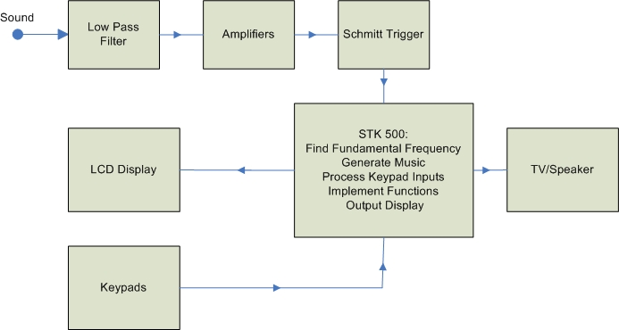
Figure 1 - Vocal Trainer Block Diagram
The most relevant standards that apply to our project are those established in music, such as the setting of concert pitches by the International Standarizing Organization in 1953. We've adhered to their convention of referring to pitches by their musical names (i.e. C,F#,A,etc). We also try to follow the code of IEEE ethics, and of course only use equipment that abides by their standards.
The following six choices are shown in a scrolling menu:
The following ten songs are shown in a scrolling menu:
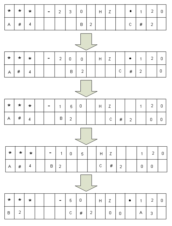
Figure 2 - Scrolling Notes
And the bottom line scrolls, as you see here in this picture taken a moment later:
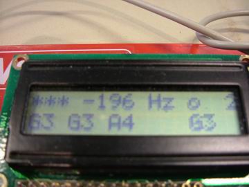
Figure 3 - Karaoke Mode 1
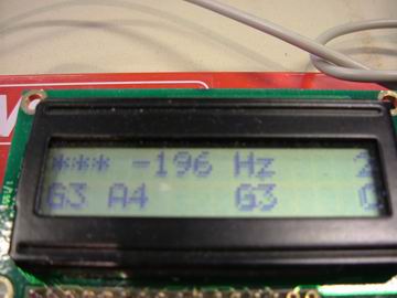
Figure 4 - Karaoke Mode 2
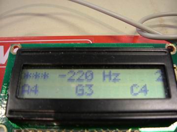
Figure 5 - Karaoke Mode 3
As you can see, the bottom line shows the notes to be played in the order that they appear in the music. The spacing between them corresponds to the relative duration of each of the notes. The note on the very left underneath the 3 '*' characters indicates the current that is playing. As time progresses, the other notes from the right will each scroll into that position and stay there for the duration that they are played. The scroll rate is proportional to the beats per minute (bpm) setting, and it also takes into account the shortest duration in the song. Also shown at the top right is the bpm that the song is playing at. A blinking 'o' is shown which blinks at the rate indicated by the bpm.
After the song finishes playing, the screen will clear and the program will return to the main menu.
The same ten songs are shown in a scrolling menu:
The same selection mechanisms are used here as in the Play Music option. After a selection is made, a countdown sequence will be initiated. When it ends, the user is expected to sing the song they�ve selected into the microphone. Again, the same scrolling notes display will be used to guide the user through this mode. However, in addition to the scrolling notes and the bpm, the user also is shown the frequency difference between the pitch they are singing and the pitch that they are trying to sing. This acts as a sort of feedback mechanism to help the user stay on track.
At the end of the song, a score is shown for the user. The score corresponds roughly to the average difference between the input pitch and the desired pitch throughout the song, and therefore, the lower the score the better.
After the score is shown, the program returns to the main menu.
In this mode, the user is prompted to create their own sequence of pitches and durations to sing. The user is first prompted to enter a pitch, which is to be entered in the format of a note pitch (e.g. A or D#) and a scale number based on international music standards. This standard, based on the formula f(N) = 27.5*2^(N/12), is represented in the table below:
|
Oct |
|
1 |
|
2 |
|
3 |
|
4 |
|
5 |
|
6 |
|
7 |
|
8 |
|
Note |
N |
f |
N |
f |
N |
f |
N |
f |
N |
f |
N |
f |
N |
f |
N |
f |
|
A |
0 |
27.5000 |
12 |
55.0000 |
24 |
110.0000 |
36 |
220.0000 |
48 |
440.0000 |
60 |
880.0000 |
72 |
1760.000 |
84 |
3520.000 |
|
Bb |
1 |
29.1352 |
13 |
58.2705 |
25 |
116.5409 |
37 |
233.0819 |
49 |
466.1638 |
61 |
932.3275 |
73 |
1864.655 |
85 |
3729.310 |
|
B |
2 |
30.8677 |
14 |
61.7354 |
26 |
123.4708 |
38 |
246.9417 |
50 |
493.8833 |
62 |
987.7666 |
74 |
1975.533 |
86 |
3951.066 |
|
C |
3 |
32.7032 |
15 |
65.4064 |
27 |
130.8128 |
39 |
261.6256 |
51 |
523.2511 |
63 |
1046.502 |
75 |
2093.005 |
87 |
4186.009 |
|
Db |
4 |
34.6478 |
16 |
69.2957 |
28 |
138.5913 |
40 |
277.1826 |
52 |
554.3653 |
64 |
1108.731 |
76 |
2217.461 |
88 |
4434.922 |
|
D |
5 |
36.7081 |
17 |
73.4162 |
29 |
146.8324 |
41 |
293.6648 |
53 |
587.3295 |
65 |
1174.659 |
77 |
2349.318 |
89 |
4698.636 |
|
Eb |
6 |
38.8909 |
18 |
77.7817 |
30 |
155.5635 |
42 |
311.1270 |
54 |
622.2540 |
66 |
1244.508 |
78 |
2489.016 |
90 |
4978.032 |
|
E |
7 |
41.2034 |
19 |
82.4069 |
31 |
164.8138 |
43 |
329.6276 |
55 |
659.2551 |
67 |
1318.510 |
79 |
2637.020 |
91 |
5274.041 |
|
F |
8 |
43.6535 |
20 |
87.3071 |
32 |
174.6141 |
44 |
349.2282 |
56 |
698.4565 |
68 |
1396.913 |
80 |
2793.826 |
92 |
5587.652 |
|
Gb |
9 |
46.2493 |
21 |
92.4986 |
33 |
184.9972 |
45 |
369.9944 |
57 |
739.9888 |
69 |
1479.978 |
81 |
2959.955 |
93 |
5919.911 |
|
G |
10 |
48.9994 |
22 |
97.9989 |
34 |
195.9977 |
46 |
391.9954 |
58 |
783.9909 |
70 |
1567.982 |
82 |
3135.963 |
94 |
6271.927 |
|
Ab |
11 |
51.9131 |
23 |
103.8262 |
35 |
207.6523 |
47 |
415.3047 |
59 |
830.6094 |
71 |
1661.219 |
83 |
3322.438 |
95 |
6644.875 |
Table 1 - Note Frequency Table
For example, the user may enter 'A5' for the standard 440 Hz, or 'C4' for middle C. The program also allows for reversed entries like '4C', which will be interpreted to be the same as 'C4.' The possible range of entries goes from 'A1' all the way to 'G#6'. However, note that 'A1' is a special character that codes for a rest note, and 'G#6' is a special stop character that the user should not input. Hence, the actual, usable range of frequencies is from 'A#1' to 'G6'. Note that all entries outside this range or of incorrect format will be cleared and will not be stored, and the user will have to enter another entry.
Entries are entered into the system only after the press of the enter key ('#' button). The user can clear the current entry before entering it by using the clear button ('*' button). If this button is pressed twice however, the program will return to the main menu.
After the user enters the pitch, the user is prompted for the duration of the note that corresponds with the pitch just entered. The user can enter the values '1', '2', '4' ,'8', '16', and '32', or any combination of these. The values correspond to the following:
|
Entry |
Note length |
|
1 |
Whole note |
|
2 |
Half note |
|
4 |
Quarter note |
|
8 |
Eighth note |
|
16 |
16th
note |
|
32 |
32nd
note |
Table 2 - Note Length
The actual durations of the note depend on the bpm setting, where the bpm setting indicates the number of quarter notes per minute.
Now the user can enter a combination of these notes, which the program will parse and add up the duration of all the values. For example, the entry '24' would be accepted as a half note plus a quarter note, or in essence, a dotted half note. '48216132' will be accepted to be a quarter note tied to an eighth note tied to a half note tied to a sixteenth note tied to a whole note tied to a 32nd note. However, invalid entries, such as '3', '15', '34', '356', or '26' will be disregarded and cleared from the screen.
Finally, at any point in the sequence, when the user is prompted for a pitch, the user may simply press the enter button to indicate that they are done entering in notes. The program also automatically goes into the next step once the input array runs out of room. Currently, the max number of pitch-duration pairs is set to be 128.
After all the entries are entered, a countdown sequence will commence, and the program will go into the same listening mode that it was in after a music selection was made in the Karaoke Mode.
The tuner mode will play a single frequency until the user hits the enter button. After that, the user will try to sing the same tone, and the program will display how far off they are from that tone. The user can then press enter again to exit this mode and go back to the main menu. The frequency to be played and sung is set in the Modify Settings section.
Here the user is prompted by a countdown sequence to start singing. When the user sings into the microphone, the pitch the user is singing will be found and the closest pitch in the standard pitch table will be displayed. For example, if a user sings at a frequency of 438 Hz, the note 'A5' will be displayed, since the input frequency is closest to the frequency of A5, which is 440 Hz. When the user is done, pressing the enter button will exit to the main menu.
This section allows to user to enable and disable various options, as well as set various settings. When the user first selects this option, they will be presented with the option of viewing the current settings or editing the settings. If the user picks to view the settings, a sequence of displays will be shown on the LCD which shows the various settings and the values they are set at. If the user elects to edit the settings, they will be presented with the following scrolling menu:
This option allows the user to change the beats per minute (bpm) setting for the program. Bpm corresponds to the number of quarter notes per minute. The default setting is 80. Usually, slow music is played between 60-90 bpm, normal tempo music is from 90-130, and fast music is anywhere from 130-200. For more precise values, refer to below:
Largo = 40-60 BPMGrace period is a short period of time at the beginning of each note when you will not be penalized for missing the exact frequency of the note. This helps take into account any slight differences when you change from note to note, and allows you to have more time to change breaths while singing. Selecting this option will toggle the grace period mode on or off. By default, the grace period is set on.
Show score is also a toggle option. Selecting it will toggle the score on or off. Default is on.
In this setting, you can modify the frequency you wish to match for the tuner. Please enter in a frequency in Hertz, not in pitch values. This way, tuner mode allows you to tune things to off frequencies not specified in the pitch table. Default tuner frequency is set to 440 Hz.
Selecting this option will toggle the option to play the notes inputted in Custom Mode. Turning it on means that after all the pitch values and durations are entered, the program will first play the entries you�ve entered before asking you to sing them. By default, this option is set to be off.
This options toggles between assuming the user is male or female. Basically, the only difference is the demo music is played an octave higher if the gender is set to be female. Default is male, for our own convenience.
This option toggles between using
the Schmidt trigger method to calculate the input frequency and the Fast
Fourier Transform (FFT) method. However,
this feature is currently not implemented.
Default is set to be Schmidt trigger.
This option auto-saves the last input in Custom Mode, and then prompts the user whether or not they�d like to load the input the previous input. Note that if a user selects 'no' at that moment, enters in new values, then presses enter again to indicate they've finished entering their pitches and duration, the new input will overwrite the old input. Pressing the menu button before the second enter key is pressed will prevent this from happening. Also, note that if auto-save is turned off, the last time the previous input is stored will remain stored, and can be accessed again when auto-save is turned on.
This section will just gives the user more instructions and detail as to how the program works. Press enter to move to navigate through the pages.
The main program is one big state machine, with many states supporting each option. Some states have also been generalized to be used by multiple modes, such as the PLAY state, which plays a given input, and the LISTEN state, which obtains the input from the microphone and outputs all the relevant displays. Flags are set by different states and used to turn on and off various options in other states. The keypad decoder is a separate debounce state machine which is accessed after 30 ms counted by a timer interrupt, and can be entered into from virtually every state. Microphone input is taken in as an external clock coming from D.3 in the Schmidt trigger mode. Sound output is produced via using Direct Digital Synthesis (DDS) method, and is outputted from B.3 to the TV audio channel or some other speaker. The LCD is accessed via Port C, the primary keypad is accessed using Port B, and the secondary keypad is connected to Port D. The last row of both keypads (A, B, C, D) has been disabled on both of the keypads, which have been rewired so that this disabling corresponds with the B.3/D.3 pin used for sound input/output.
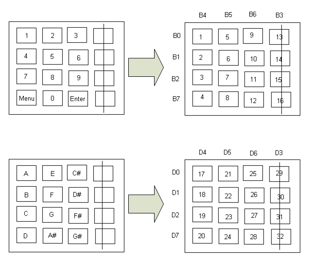
Figure 6 - Keypad Decode
| 0 | A | 17 |
| 1 | A# | 24 |
| 2 | B | 18 |
| 3 | C | 19 |
| 4 | C# | 25 |
| 5 | D | 20 |
| 6 | D# | 26 |
| 7 | E | 21 |
| 8 | F | 22 |
| 9 | F# | 27 |
| 10 | G | 23 |
| 11 | G# | 28 |
Table 3 - Butnum/Pitch Table Decode
| "String" | Butnum | Keypad Out | PORTB In |
| 1 | 1 | *1101110 | 1110*110 |
| 4 | 2 | *1101101 | 1110*101 |
| 7 | 3 | *1101011 | 1110*011 |
| * | 4 | *1100111 | 0110*111 |
| 2 | 5 | *1011110 | 1101*110 |
| 5 | 6 | *1011101 | 1101*101 |
| 8 | 7 | *1011011 | 1101*011 |
| 0 | 8 | *1010111 | 0101*111 |
| 3 | 9 | *0111110 | 1011*110 |
| 6 | 10 | *0111101 | 1011*101 |
| 9 | 11 | *0111011 | 1011*011 |
| # | 12 | *0110111 | 0011*111 |
| A | 13 | *1111110 | 1111*110 |
| B | 14 | *1111101 | 1111*101 |
| C | 15 | *1111011 | 1111*011 |
| D | 16 | *1110111 | 0111*111 |
Table 4 - Modified Keypad Scan
Below are some of the more in-depth technical details of each of the subsections and the states that compose the subsection, which can be helpful for trying to navigate through the code and figure out how the program does what in which state.
This subsection consists of the states LISTEN_INIT, LISTEN, and SCROLL_UPDATE, and is accessible from Karaoke Mode, Custom Mode, Tuner, and Easy Match. It controls the program flow when the program is listening for microphone input. Note that the algorithm for the LISTEN state will take in at least 10 input cycles and wait at least 100 ms before trying to determine the frequency when it is accessed from Karaoke Mode or Custom Mode. For Tuner and Easy Match, better accuracy is desired, and so we have LISTEN state take in at least 30 input cycles and wait at least 100 ms before trying to determine the frequency.
This subsection consists of PLAY_INIT and PLAY, and is accessible from Play Music, Custom Mode, and Tuner. It controls the program flow when the program is outputting music via the DDS algorithm.
The main menu consists of MENU_INIT, MENU_UPDATE, and MENU_WAIT states. MENU_INIT initializes the settings for the main menu, and then the program toggles between the MENU_UPDATE and MENU_WAIT states, which creates the scrolling effect. In the MENU_UPDATE state, a counter is incremented, and the LCD displays a certain subsection of the entire string. It goes back to MENU_WAIT and waits for a short duration before coming back to MENU_UPDATE to display the subsection again, now with the display window moved over by one. The program stays in these two states until the user presses a valid entry from the keypad which allows the program to transition to another state.
A menu similar in construction to the main menu is shown by using the states DEMO_WAIT and DEMO_UPDATE. These states are initialized with various flags needed for the Play Music option by ONE_INIT and ONE. After an option is selected, the program goes into the PLAY_INIT and PLAY states, where it uses the DDS approach to output the sound. Much of the code is borrowed from the sample DDS code given for lab 2, although much of it has been changed to fit this program��s needs.
Karaoke Mode uses the same states DEMO_WAIT and DEMO_UPDATE to show the menu as in Play Music. However, the settings initialized in TWO_INIT and TWO allow it to transition to the states LISTEN_INIT and LISTEN, which takes in frequencies using the Schmidt Trigger method. In LISTEN, the program toggles into SCROLLING_UPDATE to update scrolling notes shown on the LCD display.
Custom Mode uses basically uses two states, THREE_P and THREE_D to take in inputs for pitch and duration, and is initialized by THREE_INIT, THREE_INIT2, and THREE. After the user has entered all of them in, the program transitions to the LISTEN path just like in Karaoke mode. If the flag PlayInput is high, however, the program will first transition to the PLAY path before going to LISTEN.
The program initializes settings in FOUR_INIT and FOUR, and goes to the PLAY path first, and then the LISTEN path afterwards. State is changed only when the user presses the enter button.
The program sets the proper flags in FIVE_INIT and FIVE, and then goes directly to the LISTEN state.
After SIX_INIT sets the initializations, state SIX displays the first menu, and then allows the program to transition to the either the SHOW_SETTINGS state, which displays all the current user-modifiable settings, or the SET_INIT, SETMENU_UPDATE, SETMENU_WAIT states, which creates the scrolling menu in the same way as the previous scrolling menus. From there, a selection can be made to go to the various setting options.
These states have fairly obvious names, such as SETBEAT, SETGRACE, SETSCORE, SETTUNER, SETINPUT, SETGENDER, SETLISTENMODE, SETSAVE, and DOCUMENTATION. In addition, since SETTUNER displays an extra options menu, it transitions to CUSTOMTUNER when it prompts the user for actual input. From all these states, the program then transitions to the CONFIRMATION state, where it displays the change the user just made, and then returns to the settings scrolling menu.
The Debounce state machine is based off of the state diagram given in class. The transition flow is:
START à DEBOUNCE à TERMINATOR à PRESSED à RELEASEà START
Or
START à DEBOUNCE à TERMINATOR à (DONE) à START
Depending on terminating conditions. Terminating conditions depend on the key pressed, the format, and the current state that the program is in.
Other Functions:
Formatchecker:
This function checks the input of the current string entered. It is accessed when the enter button is
pressed from non-menu input states, and also parses the string to extract the
appropriate values. If the string
doesn�t pass the format checker, the debounce state machine will reset and the
current string will be cleared.
Findpitch: This function finds the closest pitch in the
pitch table given a frequency. It is
helpful in the Easy Match Mode, when the input frequency needs to be matched to
the closest note available. We used a
simple linear search through the pitch table for implementation.
Noterep:
This function is just a switch statement that displays the correct
string representation for the note entered.
For example, if the pitch 0x33 is entered, the function should be able
to set the array note to display the letter 'C'. Findpitch also sets the flag sharpOn, which
lets the rest of the program know whether or not the representation has a sharp
and a letter, or simply a single letter.
We made our program design very elaborate with many features and customizable options. As a result, the amount of time and effort needed for the program design was more than we anticipated. In addition, the code became quite long and sometimes quite painful to debug, due to the higher latency it takes to reprogram the microcontroller. However, the program has been extremely rewarding and satisfying to write, and over all, we managed to accomplish almost every single objective we set out with.
There were, of course, trickier sections of the code to write up than others, but they were well worth it. It took some time, for example, to come up with the first design for the scrolling menus, but once we figured that out, it was easy to implement them all over the place. Similarly, the scrolling notes display in the LISTEN path was quite challenging, especially coming up with a representation for the notes when the displayed notes may be variable in length. The format checking and parsing functions needed to be checked thoroughly, and it was hard to account for every case. However, by far the part that caused us the most problems was the keypad code. The implications of rewiring the keypad was more complicated than first imagined, and in fact, even after building some basic intuition, we had to resort to trial and error to finally solve the problem. However, we still occasionally have some strange keypad bugs, though they are more of an annoyance than a problem, due to the fact we��ve created safeguards such as making a clear button for non-menu input screens and providing a default case for menu input screens.
As mentioned before, the only code we borrowed was the demo code for DDS and the keypad scanner. We also tried to use the FFT code from the Numerical Recipes in C book, but that didn��t end up working for us, so we scrapped it completely.
Finally, there were a few things that we tried which did not work. Of course, the biggest one was the FFT, which was our alternative approach to find the frequency. However, that didn��t turn out to be critical because our Schmidt trigger method worked so well. There were also other minor options we would have like to have time to try, such as allowing the user to select a key signature (thus allowing for flats as well as sharps), being able to transpose to music to any key, and allow the user to switch between seeing the frequency and the frequency difference.
The hardware design, where the signal processing takes place, can be broken down into various portions. Following are the circuit schematic and the components involved in the Vocal Trainer.
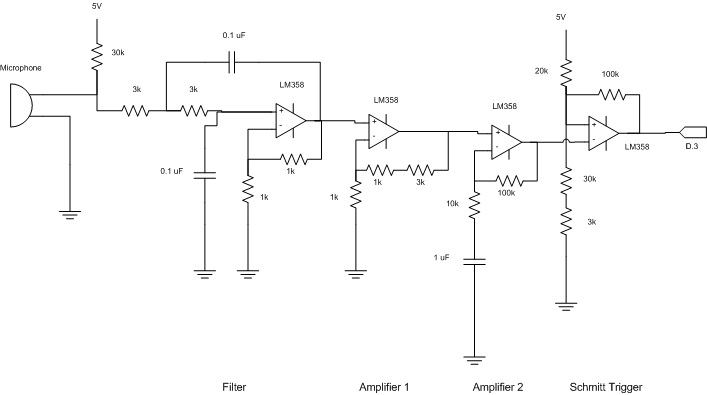
Figure 7 - Signal Processing Circuit Schematic
The microphone used is a PC microphone. In order to measure the voltage induced by sound input, we need to connect a resistor to 5 V, with the other end of the resistor connected to the output ring of the microphone. The other end of the microphone will be connected to ground. The value of resistor determines the mean voltage, amplitude, and the quality of the signal.
The purpose of the low pass filter is to filter out the noise, and possibly higher harmonics that will interfere with our fundamental frequency. Although the higher harmonics will be difficult to eliminate from our low frequency signals, finding out the appropriate cutoff frequency should definitely help. In choosing our low pass filter, we decide to do a second order filter, where the cutoff is sharper. We decided to cutoff at 1 kHz, which is a resonable upperbound for human singing. This results in a value of 0.1 uF for capacitors, and something between 1 and 2 kOhm for resistors. However, after experimenting with a signal generator, and taking into the account that the filter actually amplifies the signal, we decided to change the resistance to 3 kOhm instead, which yields better results.
The purpose of the first amplifier is to amplify the signal so that the mean voltage is around 2.5 V. The scaling of the factor 5 is determined from measurement of the signal before amplification. The result of this amplication has a mean at around 2.6 or 2.7 V, which is good enough.
The purpose of the second amplifier is to amplify the signal as large as possible, while eliminating the DC offset by using a capacitor. However, one has to make sure that the amplification factor is not too large, as such will produce undesired noise by increasing circuit unstability. Also, a factor that is too large will cause voltage saturation. As we only want the sound that is sung into the microphone, that is not what we want. We end up choosing an amplification factor of 10.
The reason we chose to use Schmitt Trigger is that, with the capability of setting arbitrary triggering voltage, we can easily adjust the circuit so that a square wave that is close to a clock signal can be produced. As the mean voltage due to amplifications is slightly more than 2.5 V, we adjust the resistance accordingly to obtain a trigger voltage at around 3.3 V and 2.2 V.
The LCD Display is used as media of communication with the user, which is operated by the program written. The connection for LCD is the same as in all previous labs.
Keypad 1 is used for inputing numerical numbers, entering inputs, changing settings, and exiting modes. It is the primary keypad. Since we will need PORTB.3 to generate the sound, and that we would like to disable the 4th column instead of the 4th row of the keypad for inputs. We need to remove the wiring for pin 8 of the keypad, and change the connection of pin 4 to PORTB.7. The decoding operation is carried out by the program.
Keypad 2 is used for inputing musical notes, and it is the secondary keypad. Since we will need PORTD.3 to take in the processed signal, and that we would like to disable the 4th column instead of the 4th row of the keypad for inputs. We need to remove the wiring for pin 8 of the keypad, and change the connection of pin 4 to PORTD.7. The decoding operation is also carried out by the program.
Either a TV or a computer speaker can be used for sound generation. The generated signal from PORTB.3 is first filtered by an RC circuit to eliminate the noise. The RC value can be anything in kHz, and is not of our major concern.
The circuit schematic is detailed enough for the purpose of rebuilding the cirucit. So with references to the pin locations and their functions specified in datasheets. One should have few trouble, if any, in rebuilding the signal processing circuit.
The circuit components are based on either past learnings or online references, where the references are specified in the references section. In choosing our op-amp, we first tried out with LMC7111, but found the slew rate to be too small, so that the transistion from diferent voltages is a bit slow. This is the reason that we chose LM358 instead, which has a higher slew rate. We also tried out the electret microphone sample that we ordered. However, due to the miniscule structure of the microphone, and that it has lower sensitive, we decided to stick with the PC microphone.
In order to determine the accuracy for our frequency detection, we did a benchmark on the Vocal Trainer. The benchmark is determined by using a signal generator and a PC speaker to generate sounds at specific frequencies, and using the microphone to take in the signal, and find out the frequency using the Easy Match mode.
| Generated Frequency (Hz) | 50 | 100 | 150 | 200 | 250 | 300 | 350 | 400 | 450 | 500 | 550 | 600 | 650 | 700 | 750 | 800 | 850 | 900 | 950 | 1000 |
| Measured Frequency (Hz) | 49 | 100 | 149 | 199 | 249 | 299 | 349 | 399 | 449 | 499 | 549 | 599 | 649 | 699 | 749 | 799 | 848 | 898 | 948 | 998 |
Table 5 - Benchmark
As we are doing the frequency detection by comparing the number of cycles of the signal with the crystal clock frequency, certain sampling time has to be determined so that the system is able to give feedback at the appropriate time. Therefore, in the Karaoke mode, we update the feedback display at a rate depending on the BPM set, while the Tuner mode and Easy Match mode update at a rate of 750 ms. The sampling time is adjusted to ensure that it is less than the display update frequency, while still ensuring that enough samples have been taken to maximize the accuracy. The keypad inputs have been set in such a way that will not be interfering with the interrupts, enhancing the executions. For the frequency range allowed, we have tested to ensure that the circuit can perform at least at 1 kHz or more, and given a good human voice, can get down to around 70 to 80 Hz.
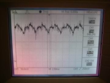
Figure 8 - Input Signal
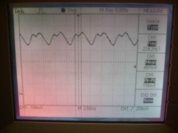
Figure 9 - Filtered Signal
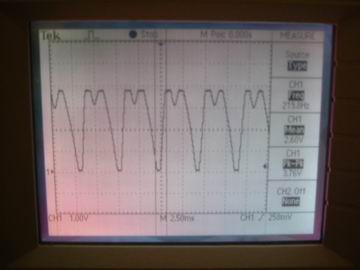
Figure 10 - Amplified Signal
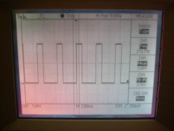
Figure 11 - Schmitt Triggered Square Wave
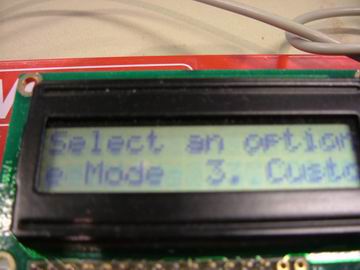
Figure 12 - Main Menu
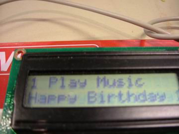
Figure 13 - Play Mode
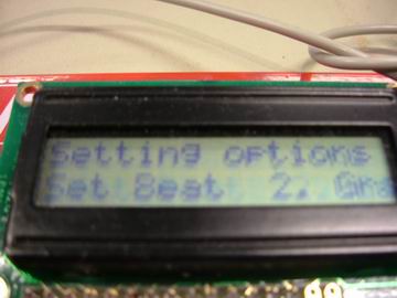
Figure 14 - Settings Mode
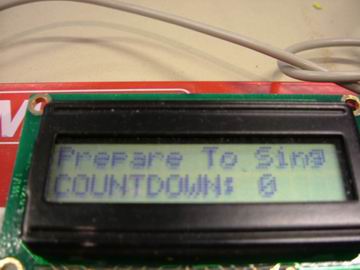
Figure 15 - Singing Mode
Knowing that while in the lab, generating higher frequencies such as 800 Hz can be disturbing to other people, we tried to minimize the number of times needed for experimenting with higher frequencies. And considering that our singing may not be good enough to please other people, we tried to sing close to the microphone and minimize our volume if possible. The frequency emitted when playing music is always in the audible range, so it should be harmless to the body. As long as the user does not turn the volume all the way up, no safety issues will be involved.
The I/O devices used for the Vocal Trainer is nothing fancy, but good enough to be user friendly. The LCD display resembles a format similar to that of the fax machines one can find out in the market. One may need several tries in getting familiar with the menu options, but overall, the system is easy to use. And the many features included are also fun to try out.
In terms of intellectual property, the only code we borrowed and modified was Professor Land's DDS and keypad scanning code given during class. Since we did not do any reverse engineering, we did not have to bother with patent and trademark issues. Also, we did not use any sampled components so there were no non-disclosures to sign either. However, there may be patent opportunities out there for our project, though I do not know of the products out there that would perform similar functions. More patent and market research needs to be done on what has been made, and what is currently available.
As we have tried to keep in line with the IEEE Code of Ethics, we would like to make it evident how we have done this. First of all, we have tried to be as honest and forthcoming in stating the claims and benchmark numbers that we have gotten from testing. Next, we have tried to limit our project to areas where we have technical competency. Besides the microphone, we have worked with all of our equipment before in lab, and we have had experience with using a microphone in other classes. Besides that, we've tried to seek out honest criticism for our work, and tried our best to implement sound suggestions. In addition, we've tried our best to treat our fellow classmates fairly without any superficial bias. Finally, we have avoided causing injury to others with false and malicious action.
In the end, we've managed to meet most of our project objectives. We've successfully designed an instrument capable of detecting the singing pitch of the human voice to around 1 Hz resolution. We've managed to create an user interface system that provides many useful capabilities and features that we planned to have from the beginning. The only regret is not having enough time to add a few more features and fix up some of the output displays. Should we do it all over again, we would have tried to distribute the workload so that we have more of it done earlier in the month.
| Components | Cost |
| STK500 Board | $15 |
| LCD Display | $8 |
| White Board | $6 |
| Keypad (2) | $12 |
| Microphone | Free |
| Speaker | Free |
| Op-amps | Free |
| Resistors | Free |
| Capacitors | Free |
| Wires | Free |
| Total: | $41 |