Introduction
We have always liked playing with remote controlled (RC) cars, so we decided it would be fun to modify certain aspects of it. This led us to the idea of changing the remote control so that the car responds to different types of input. For our project, we modified the controls for an RC car so that it responds to the tilt of a hand to drive it. By using a two-axis accelerometer to detect hand orientation, we were able to translate those movements into forward, reverse, and turn for the car. An additional control was added to interface with a PS/2 mouse to drive the car as well. A push button was used to switch between the two input types. We also added a recording and playback feature so that we could record a series of movements with the car and play them back at a later time.
High Level Design
Rationale
Simple radio control cars usually come with two joysticks to control the forward/reverse and left/right directions of the car. We thought that it might be fun to change the controls into something that might be a little easier to control, and came up with the idea of just tilting the hand to control the car. After discussing several possible options, we decided that the best way to sense tilt was to use a low-g accelerometer. Low-g accelerometers can sense the force of gravity, and as the sensor turns, the amount of force exerted on the sensor changes, and the output is changed as a result. Since we wanted four directions (forward, back, left, and right), we decided to use a two-axis accelerometer to sense tilt in the x and y directions. Later, we decided to add additional features to our controller such as the ability to use a mouse for input and the ability to record movements at the suggestions of our TAs and professor.
Logical Structure
The basic structure of our project consists of a user input, processing and analysis, and control. No modifications were done to the car. The user input consists of several subcomponents. First, there is the input for the car control. This consists of a mouse as well as a two-axis accelerometer. For the mouse, the button presses correspond to moving the car forward and backwards ľ left click for forward and right click for backwards. The user moves the mouse left and right to turn the wheels of the car left and right.. An Analog Devices ADXL203 two axis accelerometer was used to sense tilt of the hand and control the car. The user basically tilts the accelerometer in the direction he/she wants to move the car. See figure 1 for details. Another set of inputs is the playback and record buttons. There are two pushbuttons located on our board, one for start/stop record, and start/stop playback. An LED will blink to show that it is in recording mode, and the LED will be on (not blinking) if the controller is in playback mode. The third input set is the toggle to switch between the mouse and accelerometer input. This input is also a pushbutton, and each time the button is pressed, the input is switched.
Figure 1. Orientation for Accelerometer
For processing, we used an Atmel AT90-series microcontroller. An Analog to Digital Converter (ADC) is used to take inputs from the mouse and accelerometer. Based on the values read by the ADC, the microcontroller would determine what signals to send to the transmitter. All of the pushbuttons were also polled to determine whether the microcontroller needed to switch inputs or record/playback commands. The control part of project consists of a circuit to serve as the interface between the microcontroller and transmitter.
Hardware/Software Tradeoffs
We decided to use the Atmel Mega32 microcontroller since that was the microcontroller we had been using the entire semester. While we could have used a different microcontroller to save on money, we decided to use the Mega23 because we were most familiar with it. We did not want to take the risk of learning how to use a different microcontroller and possibly not finishing in time.
The majority of our code was done in C. We made this decision because we are much more familiar with C and it is easier for us to debug as opposed to assembly. For the interface with the mouse, we decided to use code from previous projects because our first priority was to get the project working. We wanted to spend most of our time working on problems where there was no documentation or existing solutions.
A custom PC board was favored over the STK board for our project. The custom PC board is battery operated, which enables us to make the controller portable. In addition, using the custom PC board offered a slight monetary advantage over the STK board. The risk associated with using the PC board is that since we are soldering the board ourselves, there is a chance of the board not working. We were fortunate enough to build a working board, however.
Relevant Standards
The main standard relevant to our project is the PS/2 Mouse Protocol developed by IBM. A pinout of the PS/2 mouse port is shown in Figure 2. The mouse uses a serial protocol to transmit data. A signal must first be sent to the mouse, after which the mouse responds with three bytes containing information related to the button push and its position and velocity.
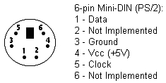
Figure 2. Pinout of PS/2 Mouse Port (from Chapweske)
Existing Patents, Copyrights, and Trademarks
We purchased the remote controlled car from a local store, and there are patents for the transmitter and patents pending for the car. The car is also modeled after the Ford GT, which are trademarks from Ford Motor Company. While we are modifying the controller, we are only doing this for personal enjoyment. We are neither mass-producing the product, selling it, or making any profit from it, so no patent rights are being violated. Our car is an official licensed product of Ford Motor Company, so the use of our car and its resemblance to the For GT is legal.
Software/Hardware Design
Program Design
The code used in this program can be found in Appendix A. The program is responsible for taking inputs from the mouse and accelerometer, keeping track of record and playback mode, and sending the correct controls to the transmitter. The inputs were done using the ADC on Port A of the microcontroller. For the accelerometer, the xout and yout outputs from the accelerometer were connected to the ADC. As the sensor is tilted in the x and y axes, the output voltage swings from 0.3 to 4.5 Volts for each output. To determine whether to move the car, we set thresholds for the sensor outputs. If the x and y outputs were above or below certain values, the proper command would be sent to the receiver corresponding to forward, back, left, right, or stop. The thresholds were determined empirically; we adjusted the values to what we felt would be comfortable positions to drive the car. One thing we found difficult in this part of the design was the ADC conversion. Due to the fact that we need to switch between input pins (Pin 3 and 7), we some time get residual of previous conversion in our current one. To solve this problem we added an extra conversion as well as a 10 ms delay. Since we don't need immediate response this fix was acceptable and our accelerometer works as expected.
Code for interfacing with the mouse was borrowed and modified from Steven Keiper and Ragavan Mahedevanĺs Paint Program page. The code was originally developed by Chee Ming, Chaw and Elaine Siu. Verbal permission to use the code was obtained from Steven Keiper. The mouse is set to remote mode and polled at a regular interval to determine whether any button has been pressed or if the mouse has been moved. When the mouse receives a ôRead Dataö command from the microcontroller, it will send a three byte packet as shown in figure 3 to the ADC on the microcontroller. The microcontroller checks to see if either button has been pressed, and sends the proper forward or reverse command to the transmitter. Left and right turn were done by using a variable to keep track of the x position of the mouse. If the mouse moves outside a certain range, a constant turn signal would be sent to the transmitter. The turn signal is turned off after the user moves the mouse back to the original position.
| Bit7 | Bit6 | Bit5 | Bit4 | Bit3 | Bit2 | Bit1 | Bit0 | |
|---|---|---|---|---|---|---|---|---|
| Byte 1 | Y Overflow | X Overflow | Y Sign Bit | X Sign Bit | Always 1 | Middle Btn | Right Btn | Left Btn |
| Byte 2 |
|
|---|---|
| Byte 3 |
Figure 3. The three data bytes sent by the mouse (from Chapweske)
A pushbutton was implemented to determine the interface (mouse or accelerometer) for controlling the car. When the microcontroller is first turned on, the input defaults to the mouse. Separate pushbuttons were used for playback and record mode. The buttons are connected to port B on the microcontroller and is polled at a regular interval of 10ms. If the record button is pushed, all commands after the push will be saved until the record button is pressed again. A signal is also sent to the LED connected to port D to toggle between on and off at a set interval to notify the user that it is in record mode. Two separate arrays are used to keep track of the command and duration. Timing is done using hardware interrupts for accuracy. When the playback button is pushed, the commands and timing are read from the two arrays and sent to the transmitter. A signal is also sent to turn the LED on to notify the user of playback mode. During this time, input from the mouse and accelerometer are disabled. Pressing the playback button during actual playback can interrupt the sequence and return control to the mouse or accelerometer. Figure 4 shows a simplified block diagram of the code.
Figure 4. Simple Block Diagram of Code
Hardware Design
The circuit for this project was pretty straightforward. After playing around with the remote control, we determined that the transmitter sends signals by shorting specific pins to ground. The controller that came with the car used mechanical levers to short the pins. Since we were using the microcontroller to control the transmitter, we replaced the mechanical switches with optoisolators. As current passes through the LED, a transistor is turned on. We connected the transistor between the pin and ground, and the LED was connected between the microcontroller and ground. A total of four optoisolators were required, corresponding to forward, back, left turn, and right turn. Figure 5 shows the circuit schematic.
Figure 5. Circuit Schematic for Controlling the Transmitter
For the accelerometer, the two outputs xout and yout were connected to separate channels of the ADC. The mouse had two outputs corresponding to clock and data that were also connected to two channels of the ADC.
Things We Tried That Did Not Work
One of the problems we had with interfacing the microcontroller with the transmitter was determining which kind of optoisolator would work best as a switch. We originally ordered several H11F1 optoisolators and connected them to the transmitter. However, we found that we were not drawing enough current from power to ground, and so no signal was being sent to car from the transmitter.
An additional feature that we wanted to implement was multiple memory slots to save commands. This would allow the user to save several different commands onto the microcontroller and play each one back separately. From the software standpoint, this would only require us to create extra arrays to store the commands. The difficult part was implementing a good user interface to allow the user to select between the different memory slots. We thought about using a liquid crystal display (LCD), but we were unable to fit the LCD onto the board with the microcontroller. In addition, we were using several pins on each port, and did not have a free port to dedicate to the LCD.
Results
After a couple weeks of programming and soldering, we were able to successfully modify the controller as we had planned. By tilting the accelerometer in different directions, the RC car drives accordingly. Holding the sensor flat will cause the car to stop. After pressing a button on the board, the accelerometer is disabled and all controls are switched to the mouse. Left clicking on the mouse moves the car forward and right clicking moves the car backwards. If we move the mouse to the left or right and then click, the car will drive in the appropriate direction. The record and playback functions also work as expected, as long as the transmitter is within range.
Safety
The car is a small vehicle that moves around, so care should be taken when operating the car around pets or small children. In addition, the car should not be operated in dangerous locations such as the street or through puddles of water. The vehicle and controller are battery operated, and must be installed correctly in order for proper operation. Failure to do so or mixing old and new batteries may damage the product.
Interference
The remote control and car operates at 27 MHz. Erratic behavior or loss of control may results from interference caused by other radio-controlled devices operating in the vicinity. If this type of behavior is encountered, it recommended that the user move to a different location for operating the car.
Usability
This product is recommended for children ages 5 and up. Anyone who is able to control a mouse or tilt a sensor in multiple directions should be able to use it. Our project was designed with the intention of being a toy for kids (and us) to play with.
Conclusions
Expectations
We were able to meet most of our expectations. In our original project proposal, we had mentioned the possibility of rebuilding the transmitter and receiver. We were unable to attempt that however, due to budget constraints. Otherwise, our car performs as expected. The inputs respond as we expect, and the interface is simple enough that our friends are able to learn how to operate it in a short amount of time. One of things that we would have liked to work on a little more was the threshold for the accelerometer to determine whether the car should move.
If we were given another chance to work on our project, we would probably design a system that would enable the user to plug in various inputs to control the car (such as the accelerometer and mouse). As of now, both the mouse and accelerometer are soldered onto the board, and it can be a bit bulky to carry around. Rather than only focus on the controls, we may add additional features to the car, such as add LEDs for the headlights and taillights as well.
Standards
The only standard that our project was concerned with was the PS/2 Mouse Protocol. After reading about how it works on various websites, we able to follow the standards and correctly interpret the output from the mouse.
Intellectual Property
We used code from another personĺs webpage, but we obtained permission before using it. In addition, we have made the proper citation for where we obtained the code. Some pictures have also been taken from another personĺs webpage, but we have cited where the pictures were obtained.
The remote controlled car has patents pending, and the transmitter is patented. In order for us to get our project working, we had to reverse engineer how the transmitter worked. We do not feel that this is a violation of patents, as we are only doing it for personal use and are not making any profit from it. As far as we know, there are no existing patents on using a mouse or hand tilt to control the car that prevents us from carrying out this project.
Ethics
We have, to the best of our abilities, conformed to the IEEE Code of Ethics. Below are ways in which we have followed a few of the points.
1. To accept responsibility in making engineering decisions consistent with the safety, health and welfare of the public, and to disclose promptly factors that might endanger the public or the environment.
We have, in every way we could think of, made the product as safe as possible. We considered ways in which the public may be hurt by our product, and have included a usability section that suggests several precautions before using our product.
3. To be honest and realistic in stating claims or estimates based on available data.
Everything in this report is, to the best of our knowledge, true. We have not purposely made any false claims, and we have reported everything as we have experienced it.
6. To maintain and improve our technical competence and to undertake technological tasks for others only if qualified by training or experience, or after full disclosure of pertinent limitations.
Before attempting the project, we had discussed both among ourselves and with the TAs about our abilities to complete the project. We submitted a project proposal that we felt used the skills and knowledge we obtained in this class, and listed goals that could be met.
7. To seek, accept, and offer honest criticism of technical work, to acknowledge and correct errors, and to credit properly the contributions of others.
Throughout the project, we have actively sought the advice of both our TAs and the professor. We gave serious consideration to their suggestions, and implemented some of the features that we felt we could accomplish. All code that we have used has been properly cited, and any other contributions have been listed.
9. To avoid injuring others, their property, reputation, or employment by false or malicious action.
We have respected all of our classmates and peers, and offered help whenever it was needed. We never damaged or sabotaged another groupĺs project, and shared all of our resources, such as the lab benches and soldering stations.
Legal Considerations
Our project is subject to FCC rules since it is a device that transmits at radio frequencies. This device complies with part 15 of the FCC rules, and its use is subject to the following conditions:
1. This device may not cause harmful interference.
2. This device must accept any interference received, including interference hat may cause undesired operation.
Appendices
Appendix A. Code Listing
final.c - link to our c program file. Click to view.
Appendix B. Schematic
Figure 6. Schematic for Entire Circuit
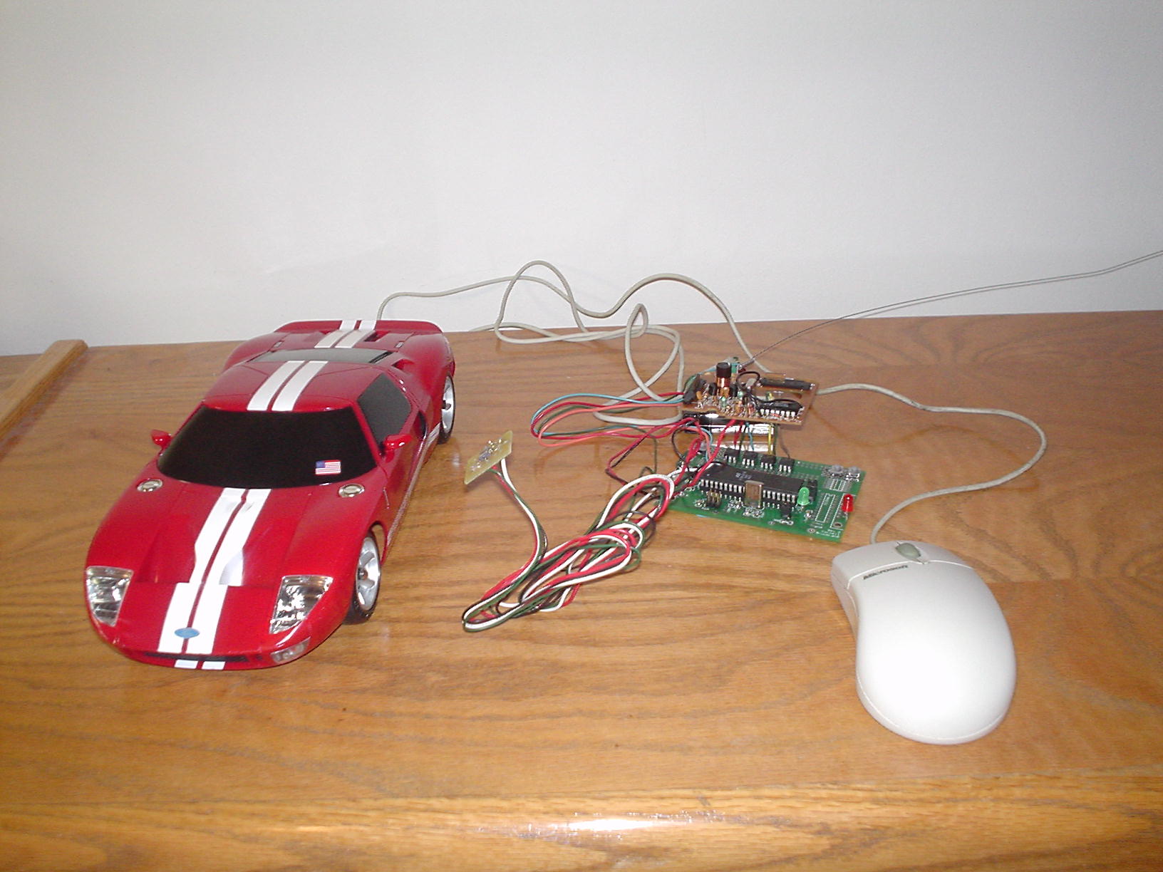
Figure 7. Actual Circuit
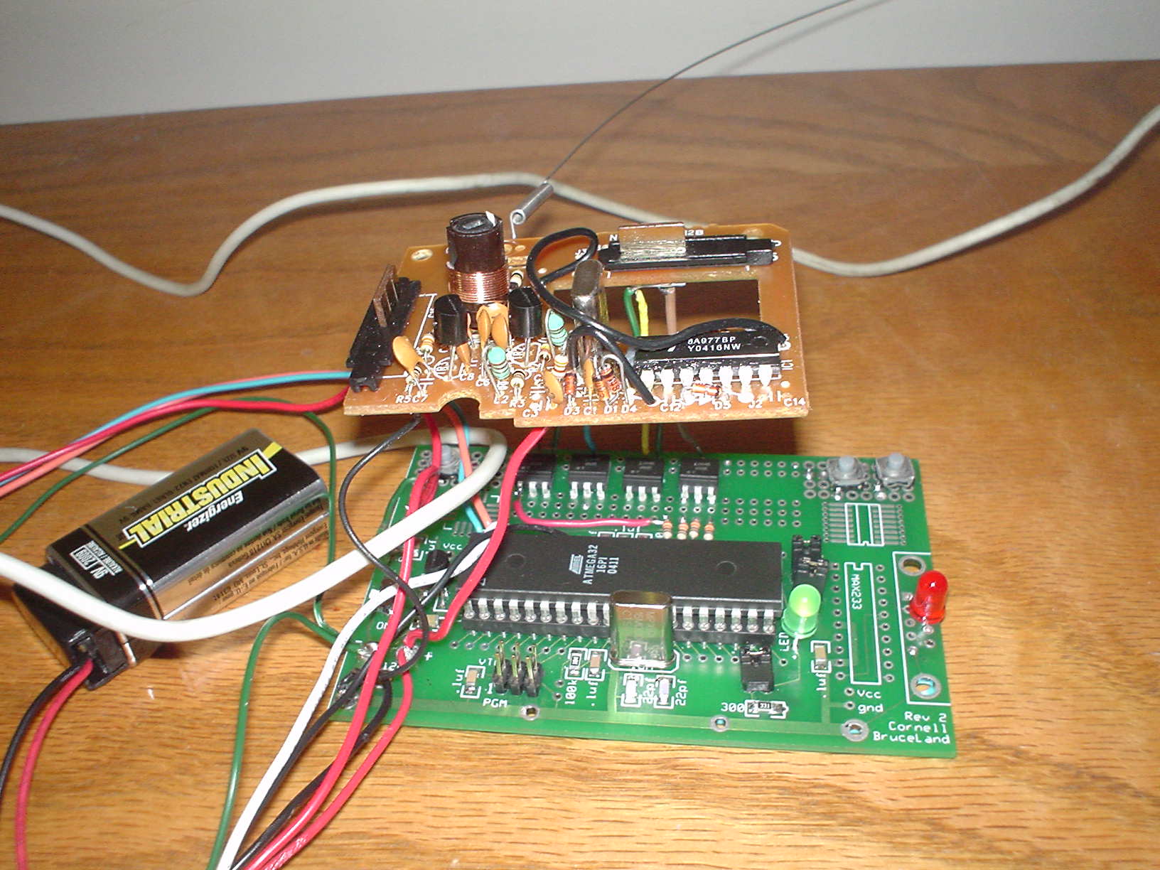
Figure 8. Closeup of Actual Circuit
Appendix C. Costs
| Item | Quantity | Price |
|---|---|---|
| Atmel Mega32 Microcontroller | 1 | $8 |
| Custom PC Board | 1 | $5 |
| Nikko RC Car | 1 | $20 |
| 2-Axis Accelerometer | 1 | $0* |
| PS/2 Mouse | 1 | $0** |
| 4N35 Optoisolators | 4 | $1.40 |
| Total | $34.40 |
*The two-axis accelerometer was a sample from Analog Devices, part number ADXL203.
**We used an old PS/2 mouse that we already own.
Appendix D. Specific Tasks
This project was split into several parts. Rather than assign specific tasks to each person, we decided to work on everything together so that we would both understand the project completely. For each task, a lead was assigned and the other person would be responsible for assisting the lead.
| Task | Lead |
|---|---|
| Programming the Microcontroller | Ming Qiu |
| Circuit Design and Layout | Bobbie Chern |
| Webpage Design | Ming Qiu |
| Report | Bobbie Chern |
References
4N35 Optoisolator Datasheet
http://rocky.digikey.com/WebLib/Lite-on/Web%20Data/4N35(37).pdf
Adam Chapweskeĺs PS/2 Mouse Interface
http://panda.cs.ndsu.nodak.edu/%7Eachapwes/PICmicro/mouse/mouse.html
Amtel Mega 32 Datasheet
http://instruct1.cit.cornell.edu/courses/ee476/AtmelStuff/full32.pdf
Analog Devices ADXL203 Datasheet
http://www.analog.com/UploadedFiles/Data_Sheets/279349530ADXL103_203_0.pdf
Digi-Key Corporation
http://digikey.com/
IEEE Code of Ethics
http://www.ieeeusa.org/documents/CAREER/CAREER_LIBRARY/ethics.html
Paint Program with Mouse Control (Steven Keiper and Ragavan Mahedevan)
http://instruct1.cit.cornell.edu/courses/ee476/FinalProjects/s2004/sdk22/Paint%20Program%20Webpage/Paint_Program.html
Special Thanks
We would like to thank Professor Bruce Land, the TAs, and our friends for all the support and help they provided us.