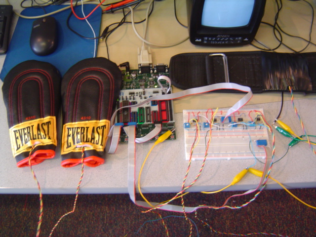
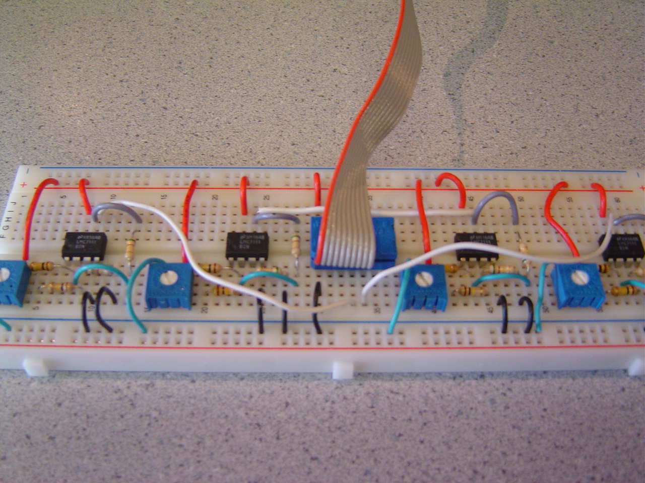
Our main hardware components are the Atmel Mega32 microcontroller, the TV output circuit, the accelerometer circuit for the glove and the body movement. The circuits are straightforward and can be easily reproduced with standard lab resistors and capacitors. (except the accelerometer). We developed our game system on the STK 500 board.
entire hardware picture
Two bits of a port are used to generate three video levels:
The circuit shown below connects the Mega32 to the TV.
The video signal is based on the RS-170 standard so there is a single waveform that is used to control both timing and luminance by varying the voltage.
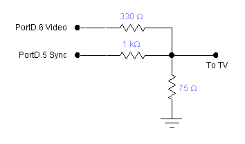
The video DAC
This single wave form contains both the sync pulses and the black and white from different pins of PORTD, these two inputs are each connected to different values of resistors to achieve different voltage levels. They are then combined together to be send into the TV video input cable. This section is excerpted from Professor Bruce Land's video generation website here.
a picture of our DAC to TV output
In order to sense the punch thrown by players, we need either a pressure sensor on a pad for the player to punch, or something that measures movement which can output some voltage for the ADC. We figured that a pressure sensor would be too easily destroyed since players won't be able to control the force they use to punch the pad, thus we resorted to using accelerometers. From looking at past projects from ECE 476, we noticed that a lot of groups used the ADXL202JE accelerometer from Analog Devices. Since there have been successful cases, we decided to go with this accelerometer.
The ADXL202E is a low-cost, low-power, complete 2-axis accelerometer with a measurement range of ±2 g. The ADXL202 can measure both dynamic acceleration (e.g., vibration) and static acceleration (e.g., gravity).The outputs are Duty Cycle Modulated (DCM) signals whose duty cycles (ratio of pulsewidth to period) are proportional to the acceleration in each of the 2 sensitive axes. These outputs may be measured directly with a microprocessor counter, requiring no A/D converter or glue logic. The DCM period is adjustable from 0.5 ms to 10 ms via a single resistor (RSET). If an analog output is desired, an analog output proportional to acceleration is available from the XFILT and YFILT pins, or may be reconstructed by filtering the duty cycle outputs.
Since we're using a ADC to acquire the voltage, we get the output from the XFILT and YFILT pins.
The accelerometer on the glove only needs one direction, thus only one output is connected to the ADC.
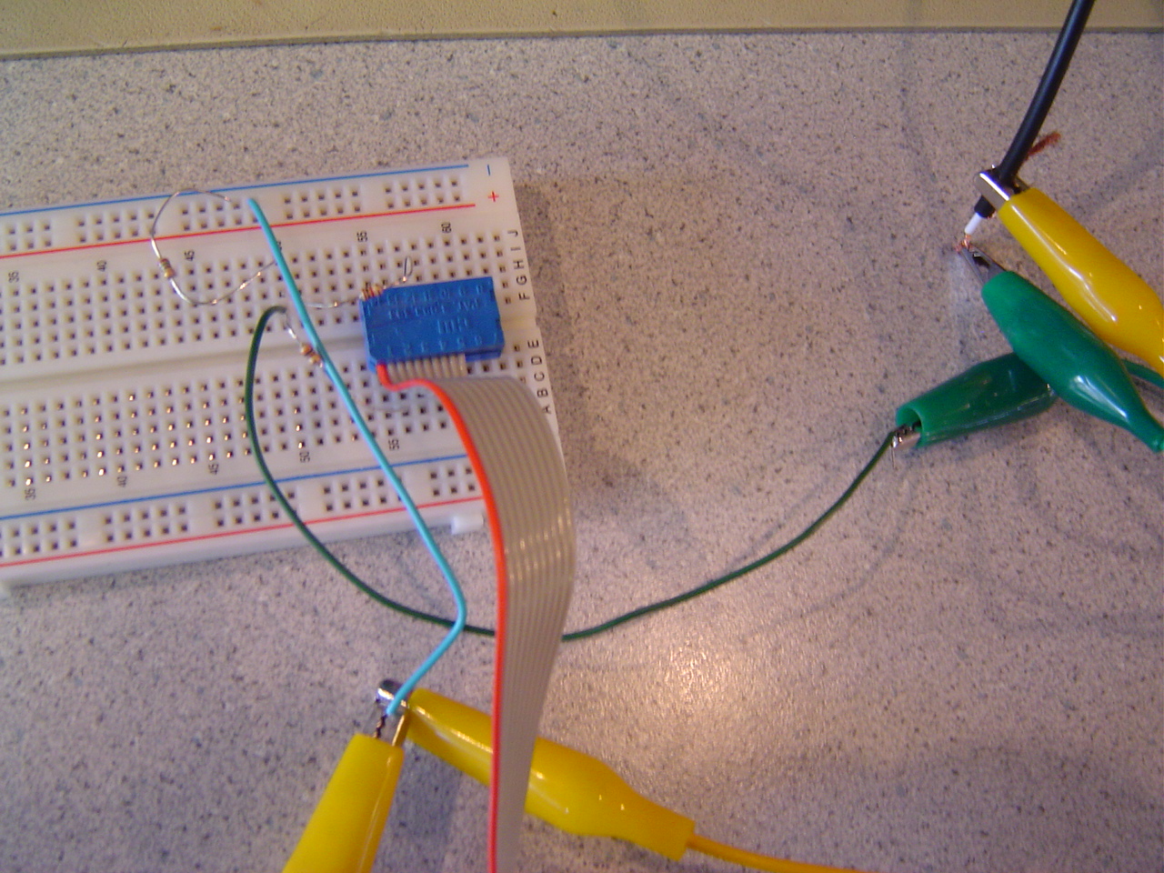
The PC board for mounting the accelerometer
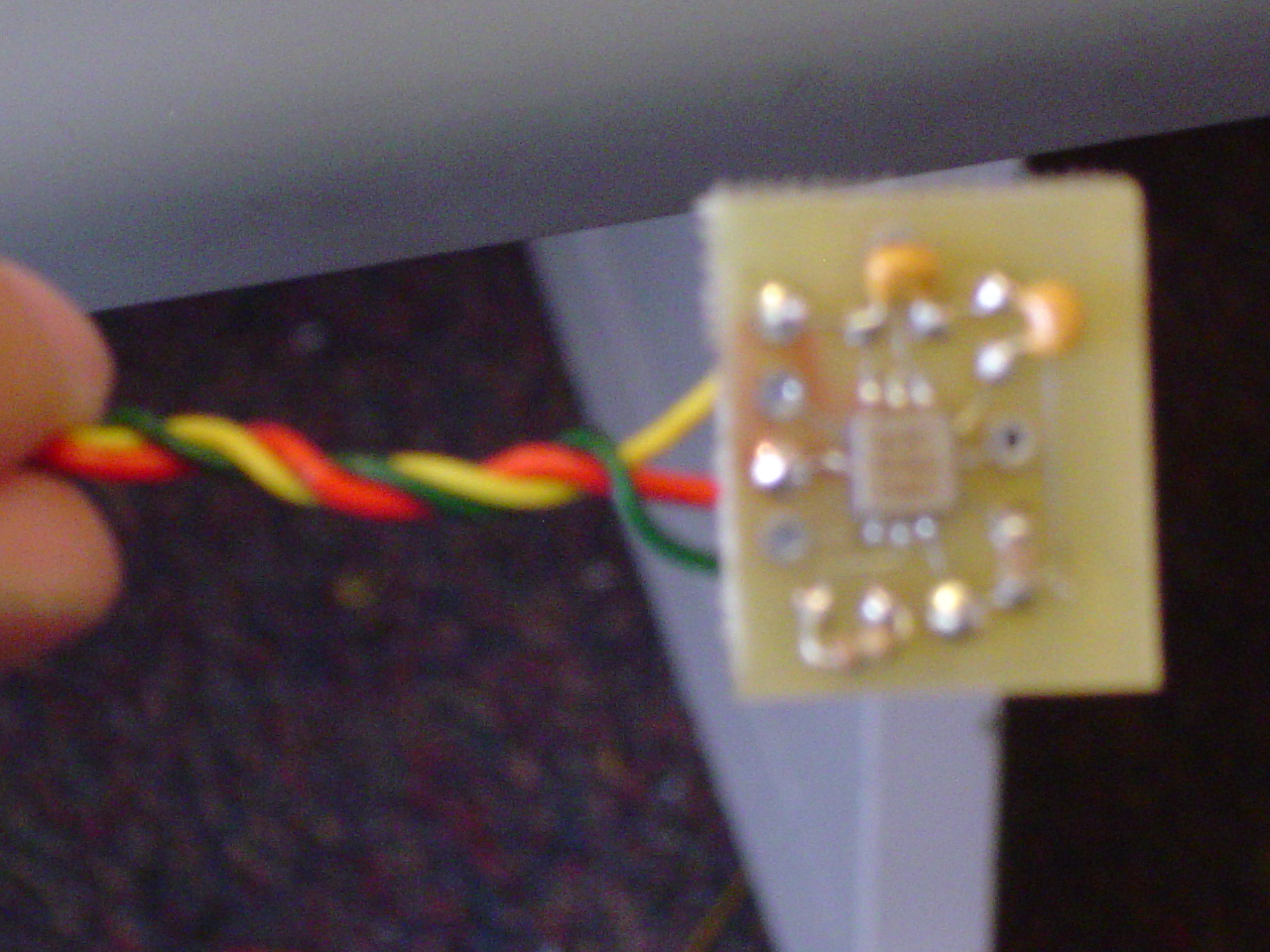
Soldered Accelerometer Board
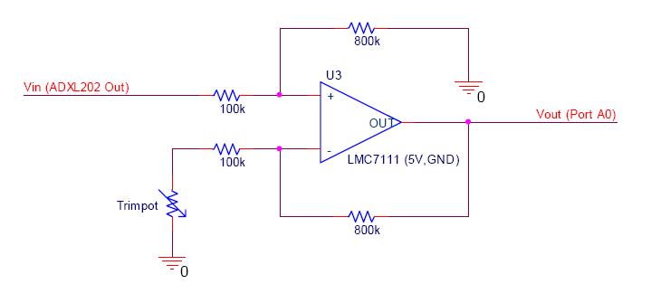
The mathematical analysis of this circuit is:
Vout = Gain* (V+ - V-)
The resistors in our project do not need to match well at all. Since we're only interested in a very crude estimation of what the acceleration is and all we really want is for it to go over some arbitrary value, thus we did not use any DIP pack for the resistors. The gain was chosen to be around 8, depending on how the person hold the boxing glove, we can change it to whatever value we want. But the most ideal gain is around about 5~8. The potentiometer is there to adjust the offset, since the initial voltage from the accelerometer is offset to 2.5 volts, and this voltage would be out of range after amplification. Thus by adjusting the resistance of the potentiometer, we can offset the voltage AFTER amplification to 2.5 volts. We calibrated this by holding the glove and wearing the belt and setting the output voltage to 2.5 volts, which is around 127, 128 in ADC terms.
a picture of our amplifier circuit
In our original design, we were going to have more complicated graphics with animated boxers throwing punches to the players with facial expressions. But we realized that the refreshing time of the TV frame is simply not enough for us to draw that much stuff on the TV screen, which results in terrible flickers and lots of artifacts on the screen. We then decided to turn off the interrupt to get us enough time to draw the objects. This, however, resulted in a really terrible gameplay with flashing screens. We finally designed a simpler graphics system which conveys the essence of the game without compromising the entertainment value.
We acquired a 3 axis accelerometer for our punches. In our original design, we were going to implement a more complicated punching and dodging combinations which makes the game more entertaining. (straights, hooks, etc) But since the position of the accelerometer in the glove depends on each player, it is almost impossible to program all the possible positions without readjusting the potentiometer and the gain of the amplifier circuit each time a different player plays. Thus we settle with the most versatile setting without compromising the entertainment value of the game.