![]()
By: Victor Liu & Michael Yu
Cornell ECE 476 Spring 2005
Introduction Design Results Conclusion Appendix
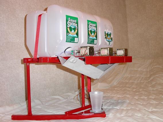
The Juicer is a wirelessly controlled, programmable juice maker which will mix each ingredient of a recipe to the exact proportions every time.
The Juicer will take a recipe selection serially via either the keyboard or the wireless remote and dispense the juices into the cup below. Force and Photo sensors are incorporated to control the precise pouring. Wireless communication is controlled with two microcontrollers operating at a frequency of 433 MHz. All of this is housed by a big red frame custom made from 4130 steel.
Imagine hosting a dinner party where you'll never have to get up and get drinks for your guests. The guests can simply enter their choice at the Juicer base station or you could wirelessly send their selection and have it ready for them to pick up.
The creation of the Juicer came from a combination of things.
We wanted:
• To create something that we will use after the course is over
• Something that would entertain and impress friends when they saw it
• To create a project that blends electronics and mechanics
• To apply our engineering skills while having some fun
Top Level Overview Block Diagram
There were some trade offs we had to make. We elected to use the proto-board rather than the STK500 so we could keep our project in complete working form after we finished. Although it took more effort to assemble the proto-board, it allowed us to satisfy one of the key goals of this project. Moreover, it cost less and allowed us to spend more of the allotted budget on making the frame structure more aesthetically pleasing to the eye.
We also decided to use RS232 communications and a computer for the user interface. We initial thought of using a keypad and LCD but elected not to in an effort to reduce costs. The complexity between using serial communications and a keypad and LCD is minimal. But by using the serial interface, we were able to easily incorporate the wireless RF communications at the last stages because it also worked serially. This tradeoff we made actually made our project more scalable for things such as the wireless RF remote control.
Another trade off was sampling inexpensive force sensors where resistance changes with change in force applied. The resistance however was not linear to the amount of force placed on the sensor and thus require software computations to interpret the output.
Moreover, we had to decrease the baud rate of the serial connection to 4800 baud to accommodate the wireless communications. The wireless transmission seemed to be unreliable at 9600 baud. By reducing the baud rate, we slowed down the software's ability to input and output serial data. However, this was not a crucial problem since the Juicer received only short input strings.
The Juicer is in compliance with FCC rules concerning Radio Frequency Devices located in Part 15 of Title 47 of the Code of Federal Regulations. We operate at a frequency of 433 MHz and transmissions are in bursts less 10% duty cycle.
We used Poland Spring 2.5 gallon spring water containers to hold our juices. We understand that they hold the patents and trademarks associated with their bottled water.
We also use solenoids and force sensors which are patented by Guardian Electronics and CUI respectively.
The Juicer is created for private personal use only and will in no way be commercialized and thus, should not infringe on existing patents.
Our initial vision was to have the microcontroller control the opening and closing of three containers. The duration of the opening would simply be timed assuming a constant flow. After further thought, we concluded that this was inadequate and simple feedback was essential for a true working model which we could keep and use in the future. Further, we wanted to challenge ourselves by creating the metal frame entirely from scratch and also incorporate a wireless remote control to the control the Juicer from anywhere with the wireless range.
Our initial consideration and one of the early challenges was coming up with a good inexpensive way of dispense the liquids. Our main concerns were that the containers must hold a lot of juice and that the dispensing mechanism needed to be cheap so we could stay within budget. Ideas ranging from pumps, solenoid valves, stepper motors finally concluded with pull solenoids controlling a modified Poland Springs 2.5 gallon spring water container that was spring loaded and naturally returned back to the closed position.
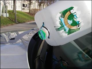
Modified Poland Spring Jug
The software is essentially one giant statemachine that is broken down into smaller ones for the ease of debugging and readability. We begin here with at top level design diagram.
Top Level Code Overview
From the stationary Juicer, the user will have the choice of making a selection, programming a new recipe, or show all the recipes. Each of these second level states will also branch into their own state machines which we will describe more in detail below.
From the remote control, the user will only be allowed to select from the first three recipes in the database. No programming or showing of the database is allowed since we wanted to make the remote compact and thus only mounted three control buttons.
After each command is complete, it will return back to the main menu and await the next selection by the user.
Three Button Remote Control

Pour Diagram
The pouring or opening of the solenoid controlled valves are controlled by the pouring routine. This routine will start with the first container and check the database to see how much to pour. The amount that is poured is determined by the force sensor that is placed below the cup. When that calculated amount is reached, it starts pouring the next container. This is repeated until all three containers are cycled through.
The initial weight of the cup is recorded before each drink is poured. We subtract out the initial weight of the cup so we can measure only the amount of fluids we dispensed. This allows us the versatility to use different cups of varying weights.
One main difficulty encounter in this step was the non linearity of the force sensor. The resistance of the force sensor did not increase linearly with the amount of force applied. This forced us to make a linear interpretation of the output of the force sensor which is not as accurate as we would have liked. Also, the placement location of the cup on the metal platform also changed the force sensors reading introducing yet another variable.
Note that the photo resistor sensor can be placed near the top of the cup to detect if the fluid is at that level. While pouring the drink, if the software detects that there is enough change in light from the photo sensor, it immediately stops the pouring cycle. The photo resistor is currently mounted on the frame and used as an emergency stop button. Simply place your finger over the sensor and pouring will stop.
The show recipe routine simply cycles through the entire database and displays the proportions of each ingredient. This consisted of a simple loop through all of the possible entries.
The programming of new recipes was achieved by taking user inputs from the keyboard. A display shows the user the format in which the program expects the inputs. The user simply enters the proportions of each ingredient.
Since our Juicer is programmable, the database is saved even if the power is switched off. We used the EEPROM feature of the Atmel Mega32 chip for the storing of the recipe data.
The RF wireless portion consisted of software that went on the transmitter and also software that went to the receiver. The receiver software was integrated with the software that runs on the base station, while the transmitter software was placed on a microcontroller solely dedicated to transmitting the user's remote selection.
The RF wireless operated at a frequency of 433 MHz. Since these devices are not unique in their frequencies and that many other groups used the same devices, we needed to devise a method to guarantee reliable communication in an air space polluted with noise. This was another difficulty that we encounter. Our solution was to transmit our packets using a unique pin that only our receiver would know. The transmitter would begin by sending a series of DC balanced characters followed by our unique pin character, followed by the command then followed by our pin again. This surrounded our command with a header and footer pin that was unique. And only when we received the data in this sequence did we process the command and begin to pour. This reduces the possibility mistaking noise, or other group's transmission, for the real thing.
At first, we attempted to transmit some DC balanced characters followed immediately by our command. This did not work reliability since many other groups were initiating their sequence with DC balanced characters also.
We also attempted to communicate at 9600 baud but found that 4800 baud was more reliable. At the higher speed, we were unable to sustain repeatability and thus chose to use the slower but steady 4800.
One of the microcontrollers is used to control all of the functions of the base station and also receive RF transmission while the other microcontroller is used to transmit data only.
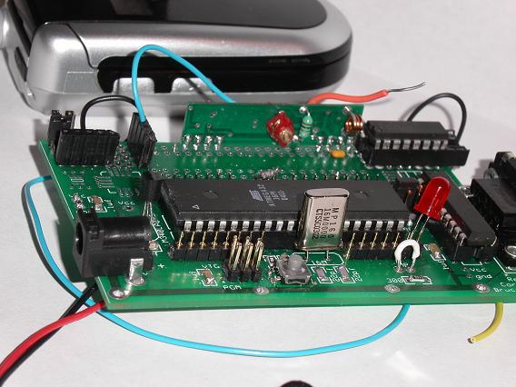
Base Station and Receiver Microcontroller
The microcontroller on the base integrates a multiplexer onboard to control input from the keyboard or from the RF wireless input. The selector of the mux is a jumper which either takes its signal from ground or from the 5 volt vcc. This selector signal is also polled by the microcontroller so it knows what data to expect. So changing the jumper setting will set the mux input as well as inform the software which mode it should be in. Note that the jumper must always be in one of the two positions. Floating inputs may not achieve the desired results.
In summary, the function of this main microcontroller is to poll for input (wireless or keyboard) and control the dispensing of the drinks based on the feedback it gets from the sensors.
To control the solenoid motors, we elected to use optoisolators. The control pins of the MCU were attached to the optoisolators which turns on and off the solenoid by controlling a TIP31 transistor. The TIP31 serves as an on/off switch for the solenoid. The optoisolators (4N35) were needed so that the MCU was completely isolated from the circuit. This protected the MCU because there were no physical connection between the MCU and the power supply. The 4N35 works by using a phototransistor that senses LEDS when the device is turned on.
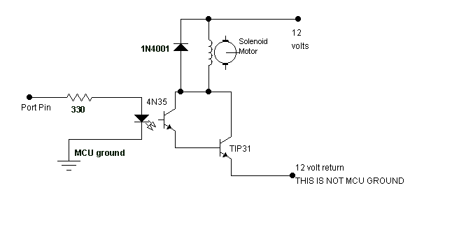
Each Solenoid Motor attached to the MCU
The sensors were measured by a voltage division circuit coupled with an operational amplifier to achieve the desired results. The voltage outputted from the sensors was sent to the ADC of the MCU. The reference voltage of the MCU ADC was set to 5.0 volts which would correspond to the digital value 255 since only the top 8 bits of the ADC were used. We simply used this digital value to determine exactly how much juice we have dispensed.
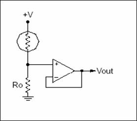
Voltage Divider Circuit for Force and Photo Sensor
The design and creation of the metal frame was quite challenging for two Electrical Engineers. We began by designing a structure that would securely hold 8 gallons of fluids. The structure would be made from 4130 steel and some aluminum scrap pieces from FASE and DARPA project teams. Most of the work was done in the GM auto lab as well as some in the Rhodes machine shop. It was fortunate because we were able to receive some welding and design help from Cornell mechanical engineers. The entire frame was welded or bolted together, sand blasted, primed and then painted for a best quality finish. This part of the project allowed us to explore our mechanical skills.
The software and circuits of the Juicer could be built from the provided diagrams and the software provided. The main concepts in the hardware and software were learned from class lectures and previous labs with the exception of the RF wireless. Without much prior RF background, we devised a simple solution which worked quite well for our application. However, designing and fabricating the valves and metal frame may not be easy for all who take ECE476. Knowledge of metal work and pure jerry-rigging may be needed to get everything working correctly.
The results of the project were better than expected. The frame that was created suited the application perfectly. The solenoids and circuits controlled the dispensing of the fluids and the wireless communications achieved better than expected results even without an optimally designed antenna.
We used timer 0 of the microcontroller to control all of our timing. Our granularity was 1 millisecond since the timer 0 was programmed to interrupt every 1 millisecond. The different tasks in the software would execute at different periods. The period ranged from 30 to 100 milliseconds. The selection for the durations was based on what was required for certain tasks. For example, the debouncing of the buttons was run every 30 milliseconds.
The dispensing of the juice, opening and closing of the valves, would be performed every 100 milliseconds. This means that every 100 milliseconds, we would check if we kept the valves open or close them. This could have been performed more frequently but is unnecessary because of the inherent delays that occur from the time when the valve is opened to when it registers to the force sensor. The fluids would have to move down the trough and into the cup before the microcontroller would know to close the flood gates. We eliminated the possibility of overflow by simply using a large cup and not filling it to the brim.
Furthermore, the accuracy of the microcontroller timer is +- 50 ppm or +-0.005%. This means for every 1 million clocks, it can be off by 50 clocks.
During the design process, safety was always a main concern. One of our main goals when designing the frame was to have it stable especially since water and electricity were involved. We created the structure so that it would be stable when 8 gallons of fluids are loaded on to it. Moreover, during the manufacturing process of the frame, we were careful in following safety protocols so that no accidents occur. We wore safety glasses during machining, and gloves during welding. This resulted in an accident free experience.
As for the software portion, we enforced safety in our design and testing process. Again, we prevented water from contacting any part of the electronics. We did this by only introducing liquids at the very end of our design. Also, in our design, we have a photo resister that we check on to make sure that the juice is not overflowing the cup. Also, in software, we do not allow any pouring when the force sensor registers above a certain threshold. We also ensured safety by using a large cup and pouring only approximately 3 quarters of it full preventing overflow. If all else fails, the reset button will stop the pouring for sure.
The interface of the Juicer is through either the keyboard or the wireless remote controller. The receiver processes commands via serial interface. And since the keyboard and wireless both work based on serial interface, the interfacing between the two modes was simple. We have a jumper on the receiver proto-board that choose wireless or keyboard mode. The microcontroller software will automatically detect the jumper position and set the software to perform the appropriate function for each mode. The jumper will also act as the select line of the multiplexer either taking input from the wireless input or the keyboard input. The jumper position, either vcc or ground, is sent to a pin on the microcontroller so it knows which mode the user wants to be in. This will allow for the receiver unit to perform the right tasks at the right time.
The Juicer met all of our expectations except for exact precision. This was because of the inexpensive, sampled, and non linear force sensors that we used. If the budget was unlimited, we could have achieved better accuracy with the force sensors and also created software that did not require linear interpolation. The overall results were quite satisfying. We began with the goal of creating a simple time-based juice mixer and ended up creating a wirelessly controlled feedback-based juice mixer. Furthermore, it was rewarding to create and to get working the mechanical aspects of the project. The solenoids, the water valves, and the entire frame were as much, if not more, of a challenge as the electronics and software.
1) to accept responsibility in making engineering decisions consistent with the safety, health and welfare of the public, and to disclose promptly factors that might endanger the public or the environment;
We worked in safety and always kept in mind the welfare of the general public. We also disclosed the purpose and intensions of our projected when asked.
3) to be honest and realistic in stating claims or estimates based on available data;
The claims made by the Juicer are purely realistic and based on available data. We know and disclose that it is not 100% precise in the way it dispenses the amount of juices.
4)... to reject bribery in all its forms
Throughout the process of this project, we never accepted any form of bribery. Although we were not offered this proposal, we kept in mind IEEE ethics and would have rejected any bribery if presented.
7) to seek, accept, and offer honest criticism of technical work, to acknowledge and correct errors, and to credit properly the contributions of others;
During initial proposal, our Teaching Assistants suggested adding more feature such as wireless to increase technical complexity. We accepted this and eventually got it to function correctly and incorporated in our project. Moreover, during the fame manufacturing, we received advice from mechanical engineers who helped us create a more stable and robust structure.
9) to avoid injuring others, their property, reputation, or employment by false or malicious action;
Again, safety was always a concern from the start. We did not compromise anyone's health, reputation, or employment during our creation of the Juicer.
The Juicer uses RF communications that complies with the FCC procedures for Part 15 of Transmitters. We operate at a frequency of 433 MHz which is within the limits of the FCC. Furthermore, we transmitted only when needed as not to interfere with others. Also, we comply to the best of the builder (our) extent to FCC regulations.
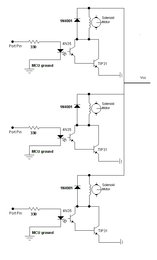
Circuit for Controlling the Solenoids
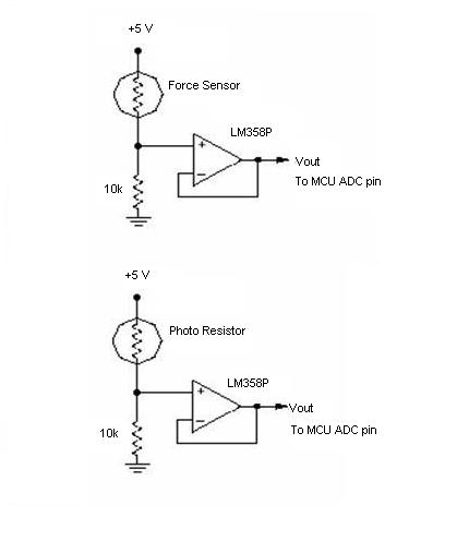
The circuits for the feedback sensors
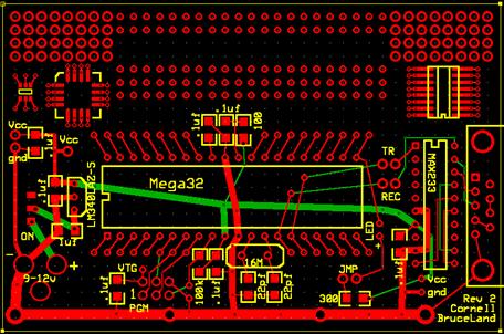
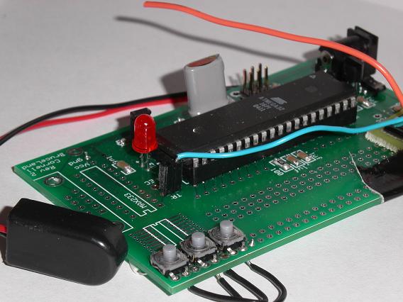
Proto Board
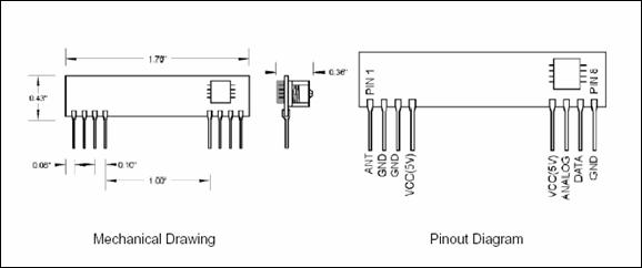
Radiotronix Wireless Receiver
![]()
Radiotronix Wireless Transmitter
The pin-outs of the 4n35 optoisolator
| Quantity | Item | price/unit | Total Price | Comment |
| 2 | protoboard | 5 | 10 | |
| 1 | rs232 connector | 2 | 2 | |
| 1 | max233CPP | 0 | 0 | sampled maxim-ic |
| 2 | mega32 | 8 | 16 | |
| 2 | wireless | 4 | 8 | transmitter and receiver |
| 3 | solenoid | 3.5 | 10.5 | all electronics |
| 1 | force sensor | 0 | 0 | sampled |
| 1 | photoresistor | 0 | 0 | from bruce |
| 1 | mux max4053 | 0 | 0 | another group |
| 1 | netgear ac/dc | 0 | 0 | had |
| 1 | frame metal | 0 | 0 | scrap |
| 1 | white board | 0 | 0 | had |
| 3 | poland spring jugs | 0 | 0 | had |
| 1 | paint | 2 | 2 | home depot |
| 1 | strap | 0 | 0 | had |
| ? | resistors and electronics | 0 | 0 | lab supplies |
| Total | 48.5 | 1.50 to spare |
Costs Price list
Victor was in charge of doing most of the management and organization of the project as well providing some of the software design and frame making and welding. His participation in Cornell Formula SAE provided the background necessary to design and create the frame structure of the Juicer. He also provided much of the software that runs the Juicer.
Michael was an integral part of the project. With his participation in Cornell Darpa Grand Challenge, he was able to provide his expertise in the creation of the metal frame. He also provided the mechanics that made the valves work appropriately. Michael also designed the hardware circuitry that runs the Juicer. He also greatly debugged and made the software robust.
RadioTronix RF transmitter and receiver
www.cui.com Force Sensors Samples
www.allelectronics.com Solenoids
http://fsae.mae.cornell.edu Scrap Metal from Cornell FSAE
www.radiotronix.com RF wireless
http://instruct1.cit.cornell.edu/courses/ee476/ All other instructions
http://www.fairchildsemi.com/ Optoisolators Samples and multiplexer
http://www.maxim-ic.com/ max233 cpp Samples
http://www.polandspring.com/ Containers to hold the juice
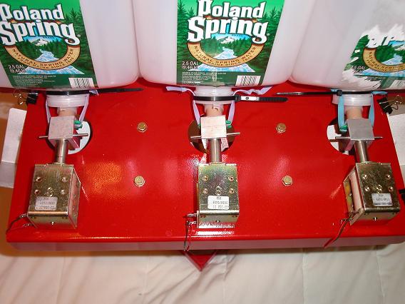
Top view of the solenoids and Design
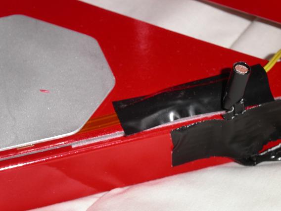
The force sensor scale and the photo resistor emergency stop
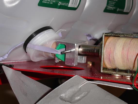
The valves controlled by solenoids
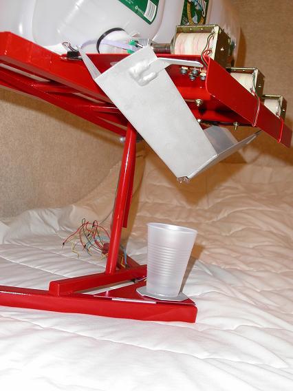
The Aluminum Trough
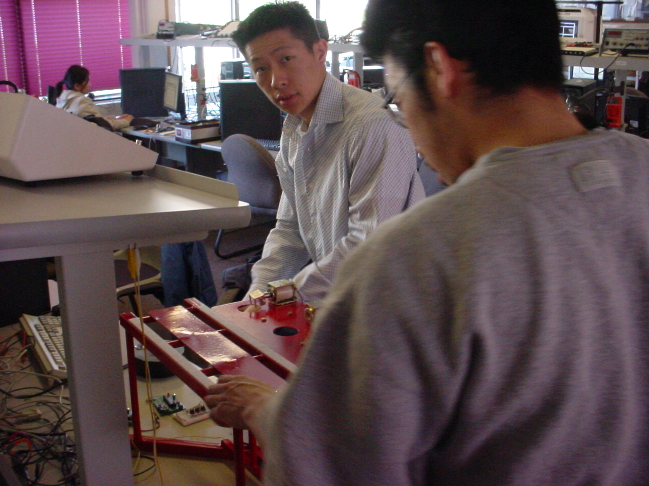
Mike and Vic working hard? or hardly working?