VOICE RECOGNITION SECURITY SYSTEM

  • ECE 476 Spring 2006
  • Final Project: Voice Recognition Security System
  • by Xiaowen Lu (xl76) and Shihjia Lee (sl362)

Extended Abstract
Introduction
High Level Design
Program/Hardware Design
Results
Conclusions
Appendix References


Extended Abstract

When we think of programmable speech recognition, we think of calling FedEx customer service call center with automated voice recognition response systems. We also think of PC-based speech recognition Dragon NaturallySpeaking. Now we took that a step further. We are talking about speech recognition in a tiny Mega32 microcontroller. We are talking about real-time speech processing which means there is no need to store the samples in an external memory at all. This was made possible by implementing bandpass filters in assembly language with fixed-point format onto the microcontroller. In this filter design, not only the output of the filter is calculated, but its square and accumulation also obtained. Thus much time is saved so that each speech sample can be processed to get its frequency spectrum before next new sample comes. In addition, the analysis of the voice is made using correlation and regression method to compare the voiceprint of different words. These techniques provide stronger ability to recognize the same word. Training procedure is also used to reduce the random changes due to one word is spoken different times. The training procedure can get the more accurate frequency spectrum for one word. The experimental results demonstrate high accuracy for this real-time speech recognition system. Back to Top

Introduction

Description of Project

The function of this speech recognition security system is to have a system that will only unlock upon recognizing a voice password spoken by the administrator or password holder.

Summary

Firstly, we looked at the speech recognition algorithm to understand the implementation. We then prepared the microphone circuit, and then proceeded to start sampling and generate the digital data for the speech. Once we have the data, we started writing the code based on Tor's speech recognition algorithm. We also wrote the digital filters in assembly code to save the number of cycles necessary for the sampling rate of the speech, which is at 4K/second. Afterwards, we analyzed the output of the filters to recognize which word was spoken. Finally, we added an LCD for better user interface to signal if the password spoken is correct or not. Back to Top


High Level Design

Rationale and Sources of Project Idea

We are inspired by the lab 3 where we did a 'Security system'. We would like to add on to that using a speech recognition feature. This eliminates the need to type in a security code. Instead, you just have to speak a password to unlock the system. We are also interested in exploring and implementing the speech recognition algorithm and DSP.

Background Math

What we need to know in this project is how to calculate the frequency to sample speech based on the Nyquist Rate Theorem. Secondly, we also need to know how to calculate filter cutoff frequency to build the high and low pass RC filter for human speech. Thirdly, we need to know how to calculate the gain of differential op-amp. We had to learn about Chebychev filters to determine the cutoff frequencies to build the digital filters for human voice. As for the analysis part of the speech, we need to know how to calculate euclidean, correlation and simple linear regression. Lastly, we need to know how the Fourier Transform works, because we need to understand and analyze the outputs of the digital filters.

Logical Structure

The structure is very simple. The microphone circuit goes to the ADC of the MCU. The digitized sampling of the word is passed through the digital filters (flash programmed onto the MCU). The analysis is done on the MCU as well. Once that is done, the LCD which is connected to the MCU displays if the word spoken matches the password or not.

Hardware/Software Tradeoffs

The software tradeoff in this project is between the number of filters we can implement and the maximum number of cycles we have to adhere to. The more filters there are, the more accurate the speech recognition will be. However,because each filter takes about 320 cycles and we could not implement more than 2000 cycles, we had to trade off the accuracy of the system and limit the number of filters to 7.

Standards applicable to design

There should be no standards that would affect this project. Back to Top


Program/Hardware Design

Program Design

Because there is not enough memory (SRAM) on the STK500, we have to deal with speech analysis during each sample interval. The key point of this project is to how to design filters and how to implement them. There are two major difficulties we need to solve: First reduce the running time of each filter in order to get all the finger prints before next new sample comes. So we have to use fixed-point algorithm. Secondly, set the reasonable cutoff rate for each filter and number of stages of the filters.
  1. Speech spectrum analysis

    Generally the human speech spectrum is less than 4000Hz. According to Nyquist theory, the minimum sampling rate for speech should be 8000samples/second. Due to our system is voice-controlled safety system; it is very helpful to analyze the speaker's voice before our actual design.

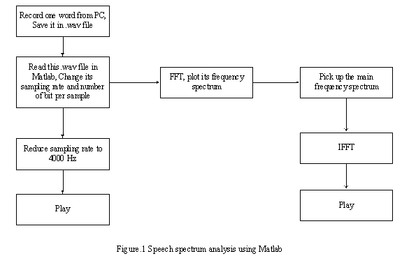
    Our design is based on the recorder program installed in Windows XP and FFT function in Matlab. After we speak one word, the recorder program will store the word in a .wav file. Notice this file is sampled at 16000 samples/second, 16bit/sample, so we need to convert it into 8000samples/second, 8bits/sample. The whole analysis procedure is as the following figure.


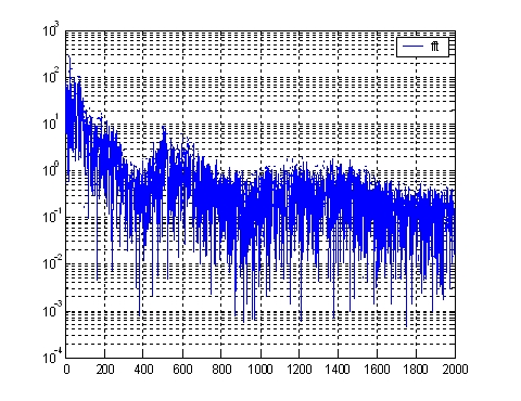
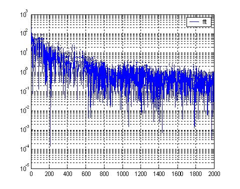
    The following figures are tester's "hello" and "left" frequency spectrum.
    Fig.2 The frequency spectrum of "HELLO" Fig.3 The frequency spectrum of "LEFT"

    From the above analysis result, we select the sampling rate in our system is 4000sample/second, 8bits/sample. The cutoff frequency for LPF and HPT is 50Hz, 1500Hz respectively. In order to get the accurate fingerprint of the code, we use seven filters, their working range are:

    • LPF: [0-50Hz]
    • BPF_1: [50-350Hz]
    • BPF_2: [350-500Hz]
    • BPF_3: [500-750Hz]
    • BPF_4: [750-1000Hz]
    • BPF_5: [1000-1500Hz]
    • HPF: [> 1500Hz]

  2. Filter Design

    From previous analysis, we know the frequency range of each filter. So first we use Matlab to generate their coefficients. Here we use ChebychevII filter.

    • Fs=4000; %Hz
    • Fnaq=Fs/2; % Nyquist
    • [B0, A0]=cheby2 (2, 20, f0); % LPF
    • [B6, A6]=cheby2 (2,20, f6, 'high'); % HPF
    • [B1, A1]=cheby2 (2, 20, [f0 f1]); % BPF

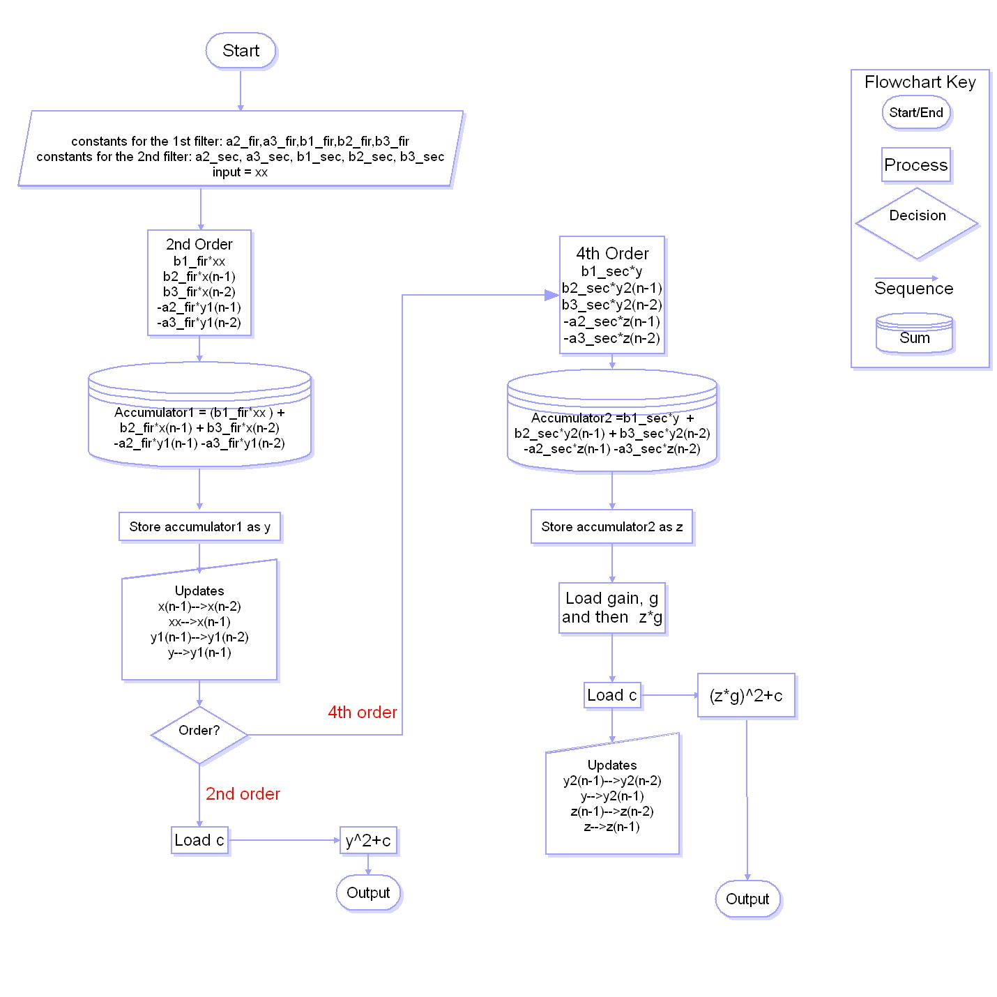
    For LPF and HPF, we just use second order filter. For BPF filters, we use fourth-order filter. In implementation, the fourth-order filter actually is cascaded by two second-order filters. The coefficients of these two second-order filters are obtained by the following Matlab command:

    [sos1, g1]=ft2sos (B1, A1,'up', 'inf');

    For the LPF and HPF filter, we take Bruce's sample code as a reference. However, we made a little change. The fingerprint of the speech is the accumulation of the square of the output of each filter. So we combine the calculation the square and accumulation in one filter function. For the fourth-order BPF, we duplicate the second-order filter but using different coefficients. After finishing our code, we tested the filter based on two cases.

    First, using an Impulse sequence to test it and compare the result with Matlab. This case is to test whether our filter correction is correct. Here we used sample impulse sequence xn=[16 0 0 0 0 0 0 0 0 0 0 0 0 0 0 0 ]

    Second, using source generator to generate different frequency sine waves and send them to the filter. The results are also comparing with Matlab's result. This case is to test whether our filter's frequency setup is correctly or not. The following figure is our test result of the second case. We print the sine wave's fingerprint to the hyper terminal and use Matlab to plot its figure.


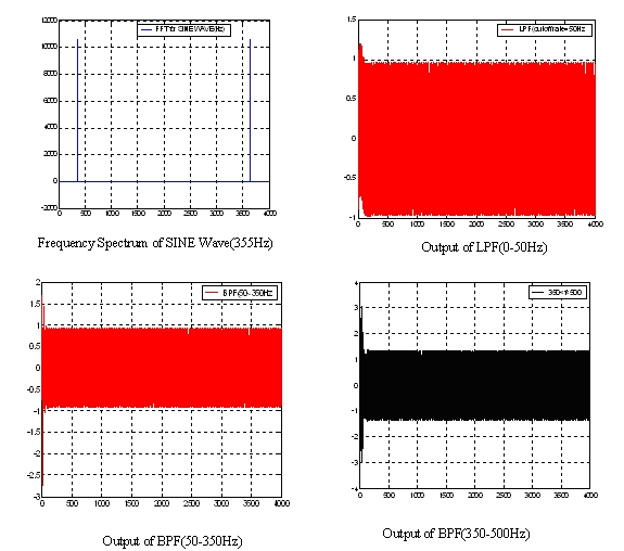
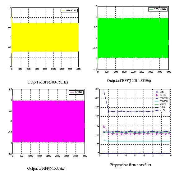
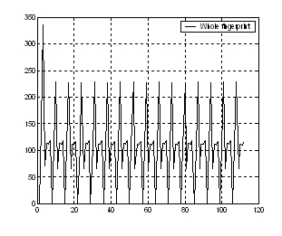
    Figure. 4 Fingerprints of sine wave (f=355Hz)

    From the above plots, the output from BPF (350-500Hz) has a maximum value, which exactly matches the testing sine wave (355Hz).

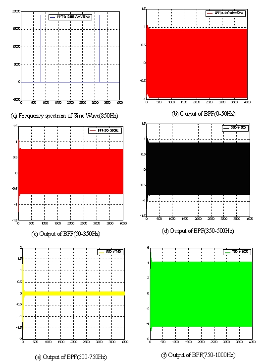
    We also use 800Hz sine wave to test our filter arrays. Figure.5 shows the result which also proves our filter design is correct.


    Below is the block diagram of the filters. 4th order filter is made up of two 2nd order filters cascaded.

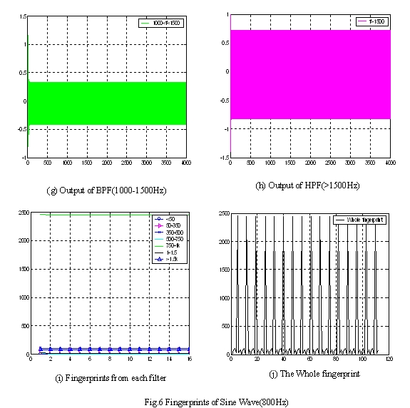
    Finally, we tested the running time of our filter. Table1 shows the result.

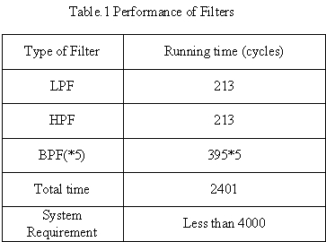
    The sample interval is 1/4000*16M=4000cycles, which is much longer than processing time of all filters. So our filter design can meet the real time requirement of speech recognition.

  3. Fingerprint analysis

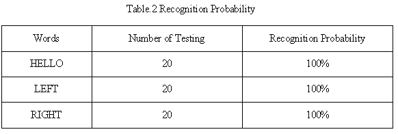
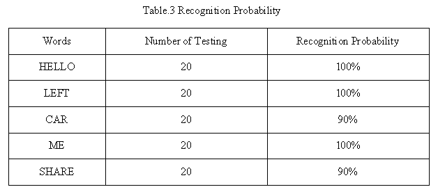
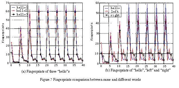
    Each sample of the speech will pass all eight filters and gets its corresponding outputs. The fingerprint of each filter is an accumulation of 250 consecutive outputs square of this filter. Basically, different words has different frequency spectrum, then it has different fingerprint. Same words have same fingerprints. However, even one person speaks the same word for several times, its fingerprints are a little different. So we need to calculation the difference of different words and compare to the difference of same words to test whether system can recognize it.

    Because LPF and HPF have some frequency components which we are not interested, in actual process, we disable these two filters and just use other five filter to analysis the speech.

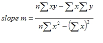
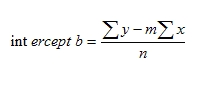
    The first method we used in this project is to calculate the Euclidian distance. That is the accumulation of the square of each difference. The formula is as following

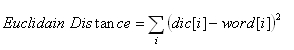
    Because all codes are written using fixed-point algorithm, the maximum value of integer is only 256. So if we use Euclidian distance, the result will overflow. To solve this problem, we first convert output of ADC, ADCH from the unsigned char to integer and send it to filter without using int2fix () function. That is, the input of the filter is always less than one. There is no overflowing anymore.

    During the test, when we plot the fingerprint of the same word as figure 7 shows, we found their shapes are similar but they have different amplitude. At that time, Euclidian distance will judge them as different words. So here we used correlation to tell the similarities of the same word's fingerprint.

    From mathematics view, the correlation is to detect the linear relationship between two vectors. Suppose Y and X and two vectors, if Y=aX+b, where a and b are constants, we say Y and X are closely correlated.

    Actually, in our project, we combine correlation and Euclidian distance together. The system first detects the correlation of dictionary and testing code. If they are distinct, the system thinks it already recognize the word. If more than two correlation results are close, and then calculate the Euclidian distance of these similar words. Pick up the minimum of the Euclidian distance as its recognition result.

  4. Comments

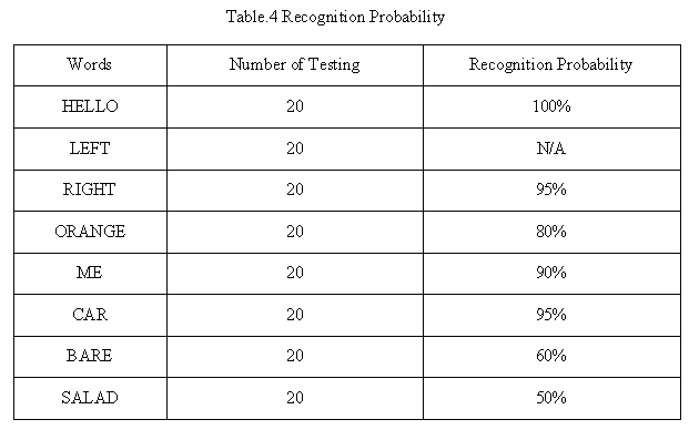
    There are two hardest parts in our speech recognition project. One is for filter design, the other is fingerprints analysis. The shortcoming for filter is its frequency spectrum resolution is coarse and can't tell the difference in its band. So we have to select some distinct words as our codes. FFT is a good candidate for filter design. For fingerprints analysis, because the outputs of each band filter are largely different, so we tried to modify the gain to equalize them. However, the improvement seems little for us.

    Another problem is when a tester spoke the same word, even if there is a tiny difference when he spoke, the fingerprint changed a lot. We didn’t solve this problem until now. But we think if we increase frequency resolutions, maybe it will be helpful.

Hardware Design

The main hardware of this project is the microphone circuit. There are three stages for the microphone analog circuit which is shown in the schematics in the appendix. The sampling frequency will be 4000Hz. It will need a high pass filter, an amplifier and a low pass filter. The first stage, an RC high pass filter uses a 1uF capacitor and a 1K resistor. The cutoff frequency is 1/(2pi*R*C) which is 159.2Hz. It is near 150 Hz, the lower limit of the human voice spectrum. This will also cut off the 60Hz surrounding noise. The next stage of the circuit is the amplifier. A three stage amplifier is needed to obtain gain desired. The gain of each stage is 10K/1K which is 10. Because there are three stages, the total gain is 1000. This is because the input voice is around 0-50mV, and the range of the ADC is 0-5V. Therefore a 1000 gain is necessary. The third stage of the circuit is an RC low pass filter. It uses a 2.2nF capacitor and a 25K resistor. The cutoff frequency of this filter is 1(2pi*R*C) which is 2895.2 Hz. It is near the upper limit of the human voice spectrum.

Another hardware is the LCD circuit is simply connected to the MCU's Port C as output. To switch between recording the password to, the switches 0,1 and 7 on the MCU are used. Switch 0 is for recording the password, up to three codes. Switch 1 is for testing a word against the passwords stored. Switch 7 is for debugging. When pressed, it will output the outputs of the digital filters. Back to Top


Results of the Design

  1. The dictionary has three words

    In this case, we first record three words and store them in the dictionary. Then record a new word. The system will recognize which word. The following is each word's recognition probability.

  2. The dictionary has five words
  3. The dictionary has eight words
  4. The result when using training

    Actually, we have a big problem during the testing. We found the fingerprint of the same word will change a lot even if his pronunciation changes a little. So tried to record the same word for 20 times and get the average of the fingerprints. But we can't calculate their average value directly because their amplitude is quite different. So we use linear regression method [1][2], i.e., try to normalize the every training sample to equivalent level then get their arithmetic average. The linear regression algorithm is as following

    The best fit line associated with the n points (x1, y1), (x2, y2), . . . , (xn, yn) has the form

    y=mx+b

    where

Back to Top

Conclusions

Conclusions drawn of the project

The project has not met our expectations fully, as we initially specified that the system would be able to recognize a sentence as a password. But we are more than happy that it is able to recognize a word as the password by more than 80%-90% of the time, depending on the choice of passwords. There is a training procedure that need to be implemented, which is an added feature to increase the accuracy of the security system. However, the system can still be used without training. In this case, there is a maximum of 5 words only.

Currently we can recognize at most eight words if we do the training. But we desperately pick up distinct words, such as [ai],[i:],[u]. We still need to make our system be robust for regular words. In the future, we are going to use SPI interface to store the speech samples to data flash, then use mel-frequency cepstral coefficients (MCC) and Vector quantization (VQ) to process the data. This will be more accurate than using digital filters.

Intellectual Property Considerations and Ethical Considerations

Referring to the IEEE Code of Ethics, we accept full responsibility for the decisions we have made in this project. We believe that the decisions that we have made so far have no potential harm on the public's safety and health, and is consistent with the public's welfare.

In our opinion, the third code, which says that IEEE members have to be honest and realistic in stating claims based on the availabe data, is especially important and applicable to our project. For the results and conclusions of our project, we have declared the accuracy of our speech recognition system. In this aspect, we have been honest and have not 'exaggerated" our numbers to make our report look good. The percentage of accuracies have been charted and calculated using Microsoft Excel and we have strived to make sure the samplings have been done fairly.

Another code of ethics that is highly applicable to our project is the seventh code, which states that members of IEEE should seek, accept and offer criticism of technical work, to acknowldge and correct errors, and to credit properly the contributions of others. With regards to the second part of the code mostly, we have credited the use of two authors whose codes we have used and modified for our project. We have also credited the group whose past final project have inspired and influenced the design of our microphone circuit. We have taken care to ensure their work have been credited rightfully throughout the report. This is also in accordance with intellectual property considerations.

Lastly, the tenth code says to asssist colleagues and co-workers in their professional development. In our case, it is about sharing with another group, Andrew and Chirag, whom we must mention here,Their group is also doing speech recognition, and (but with a robot),in this aspect, we have helped each other a lot. Neither group have been selfish despite the "competition" for grade due to the way the projects are ranked in this course. Back to Top


Appendix

Commented Program Listing

Code without flash
Code for training to build flash
Code with flash built in


Schematics


Microphone Analog Circuit


Hardware Block Diagram

Parts Cost List

  Part                                          Unit          Cost $
  --------                                      ----         --------
Digi_Key Part Number: 423-1019-ND                 1            1.46
Manufacturer Part Number: MD6030NSZ-0
Description: MIC CONDENSER ELECT NC -39+-4DB
Vendor: Knowles Acoustics
                                  
STK500                                            1           15.00
White board                                       2           12.00
Mega32                                            1            8.00 
Op amp LMC7111                                    3            0.00
Resistors 10K                                     9            0.00
           1K                                     4            0.00                                  
          25K                                     1            0.00                                   
Capacitor 1 uF                                    1            0.00 
          2.2nF                                   1            0.00
                                                            ---------
                                             Total cost:     $36.46


List of Specific Tasks

  1. Speech Recognition Design - Xiaowen
  2. Matlab Simulation of Digital Filter for Checking/Comparison - Xiaowen
  3. Hardware Design and Preparation - Shihjia
  4. Digital Filter in Assembly Language - Shihjia
  5. System Integration and Testing - shared


Snapshots

The microphone circuit The STK and MCU
The LCD circuit Both of us working on our project, picture taken by Prof Bruce
Back to Top


References

References used in this project:
Background Websites
Waner's Website on Regression
Tuft's Website on Regression
Data Sheets
Mega32 Datasheet
Debugger
Vendor Sites
Digikey
Code/designs borrowed from others
Tor's Speech Recognition Reference Code
Bruce's Digital Filters Code
Past Final Project - Digital Voice Recorder

Speech Recognition Security System
last modified: May 4, 2006