![]()
Loucetios™ is a state-of-the-art, self-configuring lighting control system solution for bedrooms, offices and perimeter areas. Under automatic operation, the system senses luminosity inside and outside a room, controls the angle of the blinds and dims the lamps to maintain a prescribed level of illumination inside the room. The system also provides the user with 4 pre-programmed ambience settings that can set the tone of the room with just a button press. Loucetios™ is an environmentally friendly system that saves energy by keeping unoccupied rooms unlit and maximizing the use of available natural light. In the long-run, Loucetios™ provides control solutions that reduce energy costs and extend lamp life.
1. High level design
1.1 Rationale
1.2 Logical Structure
1.3 Standards, Copyrights, Trademarks, Patents and Ethics
2. Hardware/Software Design
2.1 Occupancy Detector
2.2 Blinds Control
2.3 Dimmer
2.4 Light Sensors
2.5 Pushbutton
2.6 Power Supply
2.7 Automatic Operation
3. Results
4. Conclusions
Appendix A: Schematics
Appendix B: Code
Appendix C: Budget
Appendix D: Work Breakdown
References
![]() (top)
(top)
The driving force behind the idea of our project stems from the premise that Engineering is about harnessing nature to simplify our lives. Initially, we considered building an automation system to control access and illumination of a building through telephone access, thus allowing a user to remotely lock or unlock doors, close windows or switch lights on or off. However, after speaking with Professor Land about this idea we realized that developing such a system would entail many problems as phone lines are not available in the lab. We decided to modify the design and settled on a fully-automated lighting control system we call Loucetios™, after the Celtic god of Light.
![]() (top)
(top)
Loucetios™ is a system that automatically controls the light in a room based on room occupancy, lighting conditions and user objectives by controlling the intensity of lighting inside and the amount of external light coming into the room. The innovative "floating" mode, operates under the energy-saving objective. The user defines a desired level of illumination and sets the system on floating mode. Loucetios™ will keep that level of illumination in the room prioritizing the least energy-expensive decision. When sunlight outside decreases, the blinds will be further opened and only until they can't be opened will the system turn on lights inside the room.
For the user's comfort, four pre-programmed settings are available.
• Bright day
On a bright day, one can open up all blinds letting plenty of natural sunlight in and turning off the lights to save energy.
• Privacy
The Privacy setting sets a medium level of illumination while closing all blinds, providing comfort and visual security to the user.
• Intimacy
The Intimacy setting is perfect to set a romantic ambience; combining the privacy of closed binds with low lights.
• Sleep
Turns off all lights and closes all blinds so that the user can rest peacefully.
These settings are provided as factory defaults but any arrangement can be re-programmed by the user. Please refer to the Pushbuttons section for button assignments and operation details.
![]() (top)
(top)
|
The central element of the system is the ATMEL Mega32 8-bit Microcontroller. It continually takes in information from the Infrared Sensors and the Light Sensors to make decisions on the opening of the blinds and the intensity of the light bulb. The Infrared Sensors, mounted on the doors of the room, communicate to the microcontroller when they are toggled, indicating that somebody passed through the door. Depending on the direction of movement, the microcontroller determines if someone came into or left the room. The microcontroller keeps count of the people in the room and when nobody is in, the Sleep setting is activated. The light sensors are two photo-resistors mounted inside and outside the room. Each is connected to the microcontroller's Analog-to-Digital Converter to provide a numeric interpretation of the amount of light inside and outside the room. The light sensors, coupled with the light dimming circuit described below, result in a feedback loop that permits automatic control of the system. The Pushbuttons are implemented through bank of switches that communicate to the microcontroller when they are toggled, indicating that the button was pressed. The button presses are used by the microcontroller to determine whether it should operate the blinds and ligth automatically or whether it should set the ambience defined by the setting the user requests. The original objective of the project was to electronically control the dimming of the light by switching it on and off repeatedly at a higher frequency than the AC line. However, due to unforeseen safety issues with the circuits involved, we decided to mechanically control a commercially-available Lutron® dimmer. The microcontroller controls a unipolar stepper motor that pulls the sliding interface of the Lutron® device. If let go, the sliding interface is pulled back by an elastic mechanism mounted contrary to the movement the motor provides. |

Figure 1: High Level Design |
Finally, the blinds are controlled by the microcontroller through another unipolar stepper motor that rotates the shaft that changes the angle of the blinds.
Sub-systems have different power supply requirements, however, the whole system runs from two 12V, 2.5 A power supplies.
![]() (top)
(top)
Considering that lighting control systems are "the next big thing" for energy saving, there are many companies that actually manufacture similar products. We tried to make product as competitive as possible by trying to comply as much as possible with California's new energy code (Title 24) that significantly impacts lighting in new and remodeled homes. Just to provide some info, beginning October 2005, all new and remodeled homes must incorporate energy efficient lighting and controls. Depending on the room, these include:
Dimmers
Occupancy Sensors
Must be certified Title 24 compliant
Must be manual-on/automatic-off (can also be turned off manually)
Must turn off automatically in 30 minutes
Cannot be locked in a permanent "on" state
High efficacy lights - fluorescent, compact fluorescent (CFL) or high-intensity discharge (HID) lamps
Fluorescent, CFL, and HID lights must not have a medium screw base socket
Lamps rated 13 watts or greater must have an electronic ballast
Though we did not have time nor money to work on the ballast, we think that all other points were covered.
Furthermore, RS-232 was implemented for communicating between the Mega32 and the Computer terminal. Other than those, after a reasonable search for such items, we really didn't find infringement of any existing patents, trademarks or copyrights.
The IEEE Code of Ethics describes the professional standards all Electrical and Electronic Engineers are expected to abide by. The full code is shown below, with a description of how each section was related to our project experience.
1. To accept responsibility in making decisions consistent with the safety, health and welfare of the public, and to disclose promptly factors that might endanger the public or the environment;
Our product does not pose any hazards or safety issues to the consumer. We have all the wires for the circuits and power supplies covered with electric tapes to inhibit any unintentional contact with human skin. The light dimming module (provided by Lutron™) was uncovered to build the control system and can cause shock if touched. However, we covered the module with electric tape such that no one can pierce their finger through (unless they really want to).
2. To avoid real or perceived conflicts of interest whenever possible, and to disclose them to affected parties when they do exist;
There was no other lab group working on the same or anything similar to our project, and hence, there were no conflicts of interest.
3. To be honest and realistic in stating claims or estimates based on available data;
We did not manipulate or exaggerate our results or data in any form. We have disclosed all the codes and reference pictures to support our arguments made in the lab report. All costs incurred and prices of components are listed as per instructions and are true and accurate.
4. To reject bribery in all its forms;
Bribery… eh?
Abhijeet: Yo Marcelo, didn’t Eric just buy a Kawasaki?!?!?
5. To improve the understanding of technology, its appropriate application, and potential consequences;
Our project used various technologies of which our group members were not familiar with at the inception. We made sure we used the technologies for its appropriate applications. We have also made our best effort at communicating what we designed and how it should be used.
6. To maintain and improve our technical competence and to undertake technological tasks for others only if qualified by training or experience, or after full disclosure of pertinent limitations;
We designed and built the project solely for our interests and the course purposes. This was a great project experience and we definitely learnt a lot.
7. To seek, accept, and offer honest criticism of technical work, to acknowledge and correct errors, and to credit properly the contributions of others;
Our primary source of criticism and contribution was Prof. Bruce Land to whom we shall remain ever indebted. NB: He has been referenced (and ranked first) in our reference list.
8. To treat fairly all persons regardless of such factors as race, religion, gender, disability, age, or national origin;
Our group diversity shows how we embrace and appreciate diversity in the workplace!
9. To avoid injuring others, their property, reputation, or employment by false or malicious action;
We did not take part in any of the above mentioned malicious activities.
10. To assist colleagues and co-workers in their professional development and to support them in following this code of ethics;
By all means!
![]() (top)
(top)
|
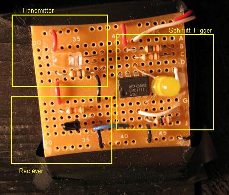
An occupancy detector circuit was built using a pair of infrared transceivers (Receiver: LTR-4206E; Transmitter: LTE-4208). When an opaque object is put in between the aligned transceiver current flows through the receiver. Putting one transceiver on a door could be used to determine whether someone crossed the door, however, two are needed to determine the direction of the person crossing the door. The voltage that develops across the receiver is dependent on the opaqueness of the object and the distance between the transmitter and receiver. To deal with this, two inverting Schmitt Triggers were designed using a LMC7111 Operational Amplifier. Each Schmitt Trigger was designed to have a low threshold of 1.55 V and high threshold of 2.08 V. This design permits easy interfacing with the microcontroller as it provides an active-low signal to indicate a specific sensor has toggled. The transmitter/receiver pair has an active range of detection of about 10° and were tested for acceptable operation of 2m. The actual circuits were mounted on the frame for demonstration purposes, as the picture on the right shows. |

Figure 2: Occupancy Detector Circuit mounted on frame. |
The diagram below illustrates the Occupancy Detector Circuit, and the image to the right of that shows a receiver and a transmistter circuit (which do not communicate with each other).
Figure 3: Infrared Occupancy Detection Circuit |
Figure 4: Actual Transmitter, Reciever and Schmitt Trigger. |
The circuit feeds information to the microcontroller, so an appropriate algorithm needed to be developed. Conceptually, when a person walks into the room through a door with the sensors, Sensor A is toggled first followed by Sensor B. Similarly, when a person leaves the room, Sensor B is toggled before Sensor A. In order to account for cases when a person walks half-way through the door (toggling only Sensor A) and decides to reverse direction and leave never entering the room, the following algorithm was implemented:
The number of people in the room will only be increased if the sensors are toggled in the following specific order:
In an analogous manner, the number of people will only be decreased if the following sensors are toggled in order:
All other combinations are ignored
The actual code developed for this circuit is listed below.
if (sensorA && !sensorB)
{
if((traffic == NONE)||(traffic == IN_M)) traffic = IN;
}
else if (!sensorA && sensorB)
{
if((traffic == NONE)||(traffic == OUT_M)) traffic = OUT;
}
else if (sensorA && sensorB)
{
if(traffic == IN) traffic = IN_M;
else if (traffic == OUT) traffic = OUT_M;
}
else if (!sensorA && !sensorB)
{
if(traffic == OUT_M)
{
if(num_people != 0) num_people--;
PORTB = ~num_people;
}
else if(traffic == IN_M)
{
num_people++;
PORTB = ~num_people;
}
traffic = NONE;
}
![]() (top)
(top)
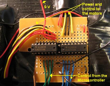
To control the angles of the blind and the Lutron™ dimmer we made use of two unipolar stepper motors (PF35T-48L4 and a functionally equivalent one as described in the Dimmer section). The rationale for using stepper motors (as opposed to other types of motors) are their high precision movement and better control due to its rotation in fixed discrete steps. To provide sufficient power and torque to these motors, we used 9V as power supply along with the ULN2003AN (High-voltage, high-current Darlington arrays) which provide the current necessary to drive the motors and that the microcontroller cannot supply. This circuitry is shown below.
Figure 5: Darlington arrays used to source current to motor. The stepper motor’s electrical input consists of six wires; four for control and two for power supply. In order to drive the motor, a particular sequence of high/low voltages is required to be applied to the four control wires. |
Figure 6: Blinds Control stepper motor. |
The documentation we found online claimed a two-hot assignment of codes which we later found out was not the only way to control the motor. Using two-hot assignment results in an increase of about 1.4 times in torque at the expense of twice the amount of current. The motor can also be controlled by four one-hot assignment codes. The blinds control required the torque that is created by using two-hot codes, while the dimmer only needs the torque generated by the one-hot codes. The motor set-up for the blinds is shown above.
Both motors were connected PORTB of the microcontroller (Pins 0-3 for Blinds control, pins 4-7 for dimmer control). Series of binary sequences are sent with a timing delay of a couple of milliseconds to adjust for the speed needed from the motor. The control code sequence for the motor looks like:
PORTB = ~0b00001001;
PORTB = ~0b00000101; //after some time delay
PORTB = ~0b00000110; //-do-
PORTB = ~0b00001010; //-do-
Or
PORTB = ~0b00000001;
PORTB = ~0b00000100; //after some time delay
PORTB = ~0b00000010; //-do-
PORTB = ~0b00001000; //-do-
The blinds had to be calibrated for a numerical value of maximum and minimum motor steps.
![]() (top)
(top)
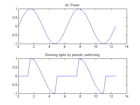
Part of setting the right ambience in a room is controlling the intensity of the lights. Very bright lights have a much different effect on people than low lights. Loucetios controls the intensity of the light by dimming an incandescent light bulb. Dimming can be achieved in different ways, the most straightforward being a variable resistance that varies the voltage coming in to the lamp. However, variable resistance dimming is very inefficient in terms of energy, as the resistance is turning energy into heat that is not used. An efficient way to dim an incandescent light bulb on AC power is to periodically turn off the AC sinusoid and thus provide only a fraction of the full wave to the light. At first this might sound counterintuitive as it would create flicker, but if the phase of the AC power and the periodic switching of the light are locked, the flickering is not perceivable by the human eye. The concept is illustrated by the figure on the right. Two circuits are needed to achieve the dimming: a pulse-controlled switch and a zero-crossing detector. The latter is used to keep the switching in phase with the power source. Safety precautions had to be implemented in order to deal with the 120 V AC source. The circuitry had to be electrically and mechanically isolated from the outside through optoisolators and a metal box, respectively. The pulse-controlled switch consists of a triac and a diac. If input a periodic pulse, the circuit 'blocks' the AC line with the pulse. The zero crossing detector is essentially a full-wave rectifier with high-power resistors to diminish the voltage. Unfortunately we encountered problems with the diodes in the full wave rectifier more than once, twice creating short circuits that burned our circuits. In the interest of safety this approach was left out of the project and a mechanical approach was designed. |
Figure 7: Illustrative example of dimming an incadescent light bulb by periodic switching. |
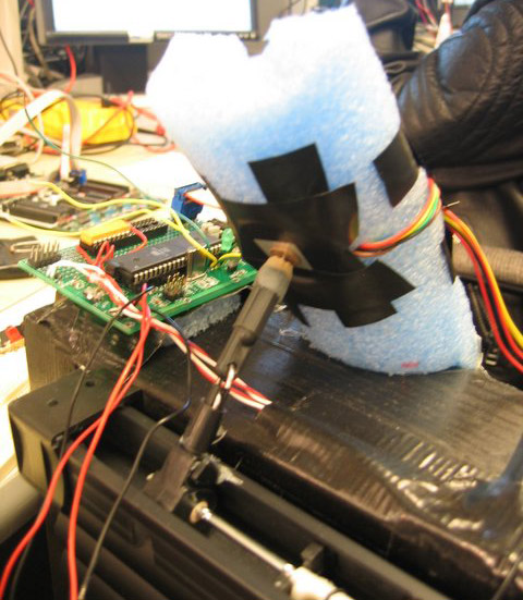
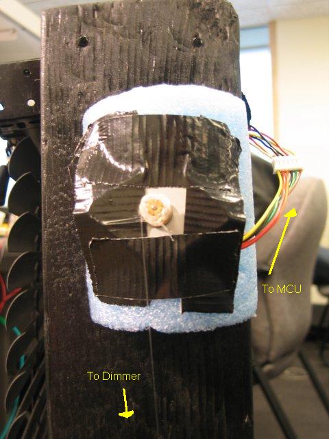
Due to the problems described above, we decided to seek a mechanical alternative to dimming the lights. We had available a Lutron® incandescent light dimmer which we had tinkered with to learn about dimming circuits. Using another stepper motor as the one described in the Blinds section we tied the motor to the dimmer with fishing line. To provide the movement back to the original position when the motor is no longer holding the dimmer in position we mounted an elastic band attached to a fixed position that provided the necessary force to bring the dimmer slider back to position. The code to control the motor is seemingly identical to the one described in the Blinds section, specifically this motor is controlled by pins 4-7 of Port B. The figures below show the final assembly of the dimmer and motor.
Figure 8: Dimmer Motor mounted on foam. |
Figure 9: Lutron Dimmer controlled by the dimmer motor on the right. |
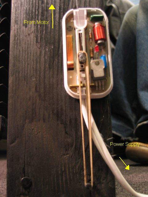
However, this solution required holding the motor in position when the desired dimming level was achieved. This means that the motor must be sourced current constantly to keep it on hold. Not only is this energy inefficient, but also it required high amounts of current (in the order of 800 mA per motor) that the power supplies availabe can't source properly, thus creating a serious heating problem. We only discovered this late in the development process and had to completely redesign the mechanical solution and control code for both the dimmer and the blinds.
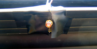
We required a mechanical design that would allow for the motor to be off during the times that it was not moving the dimmer. We scrounged a scanner for the track and belt that is used to move the scanning head and reassembled the parts. This new solution means that the motor only draws bursts of current when it is needed for adjusting either the dimmer or the blinds. This helped reduce the usage of power and allowed us to uphold our project’s dictum. The figure below shows the new mechanical solution as implemented.
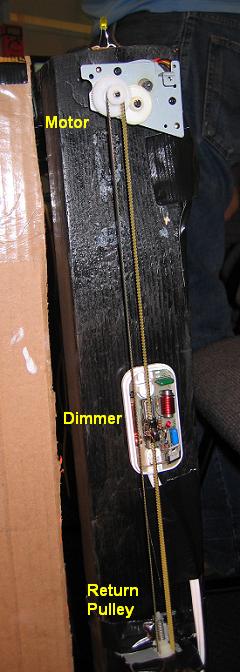
Figure 10: Implemented Dimmer
![]() (top)
(top)
To measure the intensity of light inside and outside the “house”, we acquired a pair of photoresistors (CL905L) from Prof. Bruce Land. This light dependent resistor is an electronic component whose resistance decreases with increasing incident light intensity and vice-versa. This module was connected with another resistor is series in the form of a voltage divider shown on the right. The output of the voltage divider was connected with the Analog-to-Digital Converter input of the microcontroller to acquire the various voltage levels. The figure below shows the final assembly of the photoresistor pointing to the inside of the room. Since the resolution of the microcontroller’s ADC is 8-bits, the ‘digitized’ output of the voltage divider ranges from 0 to 255 units. This range span was divided by 2 (i.e. have it range from 0 to 127 units) in order to reduce the sensitivity of the light sensor. An upper limit was set at 100 units which makes it convenient to define the step sizes of luminosity inside the room. Hence, steps sizes of 10 were decided upon which results in 10 different intensity levels for the users to choose from. |
Figure 11: Light Sensor mounted on frame |
Figure 12: Light Sensor Circuit |
![]() (top)
(top)
Since the ports on the microcontroller are active low, the following circuit was implemented in order to connect pushbuttons:

Figure 13: Pushbutton Circuit Diagram. |

Figure 14: Pushbutton Implemented Circuit. |
When the button is not pressed (open switch), the port on the MCU is connected to Vcc through a 1KΩ resistor. Assuming infinite input impedance, the MCU will also going to be tied to Vcc. When the pushbutton is depressed (short circuit), the MCU will be connected to ground, toggling the port.
The controller can be fully programmed with only eight pushbuttons. The first four buttons S1-S4 are pre-set ambiances that can be recovered by pressing the buttons once.
One pressing of the Float button makes the controller enter the automatic operation mode, which is explained in more detailed in the automatic operation section.
When in Float mode, the buttons Plus/Minus can be used to increase or decrease the floating value.
The button operations are summarized in the table below:
Button Number |
Single Press (default) |
Press and Hold for 2 seconds |
Hold "manual" button and... |
|---|---|---|---|
1 |
Setting 1 (Bright day) |
Save current conditions as Setting 1 |
Open (one step) blinds |
2 |
Setting 2 (Privacy) |
Save current conditions as Setting 2 |
Close (one step) blinds |
3 |
Setting 3 (Intimacy) |
Save current conditions as Setting 3 |
Brighten (one step) lights |
4 |
Setting 4 (Sleep) |
Save current conditions as Setting 4 |
Dim (one step) lights |
5 |
Enter Float Mode |
- |
- |
6 |
Increase Illumination |
- |
- |
7 |
Decrease Illumination |
- |
- |
8 |
- |
(Hold to use with other buttons) |
- |
![]() (top)
(top)
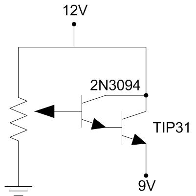
As mentioned previously, the development of the system faced hardships in terms of supplying adequate power to the system. The high current requirement rendered it difficult to run reliably on batteries. There are two different voltage requirements on the system, motors run on 9 V and the microcontroller, occupancy detector and light sensors run on 5 V. Given that the only available power supply with more than 2 A of current was 12 V we had to build a Darlington-based voltage regulator. Feeding on the 12 V supplied by the transformer of the power supply the circuit supplies the main power for the system at 9 V. The 5 V needed for the other circuits was provided by a LM340T5 9 V to 5 V regulator.
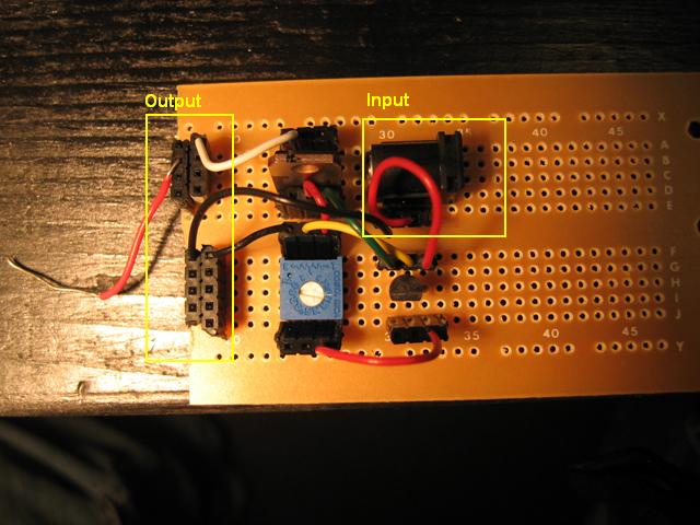
The Darlington-based regulator consists of a variable resistor, a TIP-31 transistor and a 2N3904 transistor as shown in the circuit diagram on the right. The variable resistance on the base of the 2N3904 provides variable output which we set to 9 V as our motors require. The final assembled circuit is also shown on the right.
Figure 15: Voltage Regulator Circuit Diagram |
Figure 16: Voltage regulator as implemented |
![]() (top)
(top)
When set to the automatic operation mode, the sensor takes full control over the blinds and the light dimmer. The controller adjusts the blinds and the dimmer in order to maintain a constant amount of light in the room, which is pre-determined by the user. This pre-determined light amount, called "floating value" can be increased or decreased at any time by pressing the "plus" or "minus" buttons on the controller. The coordination of the movements of the blinds and the dimming of the lamp is done prioritizing energy savings i.e.: When it is brighter outside, the controller opens up the blinds before turning the lights up. Similarly, when the inside is brighter than the set value, the lamp is dimmed first before the blinds start closing. This control implementation is included in the code appendix.
The automatic operation also enters the privacy mode closing the blinds when it sees that the light indoors is greater than outside and the light outside does not contribute to the illumination of the room. This procedure prevents the room from being exposed during night times increasing the security of the facility.
![]() (top)
(top)
The final Loucetios™ prototype yielded exceptional performance:
Under floating mode, the system converges within a 1 unit of illumination of the user's goal, which to the human eye, is perceptually indistinguishable.
The code is lightweight and does not crash the microcontroller, which suggest a smaller microcontroller could be used in an upgraded version of the system, or more features can be easily added to the system.
Drastic changes in lighting are very uncomfortable, as the physiology of the eye adjusts slowly. Because of this, speed of execution was not a concern and our motors are deliberately set to be slower than their maximum speed.
A very stable and strong frame and assembly of parts gave the Loucetios™ prototype the mechanical stability necessary for the parts not to move when the motors are off and not holding the dimmer or the blinds in place. Because of illumination changes will not occur inside the room unless the bulbs burn out, or there is no electricity to power the system.
The user interface is incredibly simple and friendly. With a simple table as the one shown in the Pushbuttons section, anyone can make full use of Loucetios™ and all its features. All buttons were thoroughly tested for appropriate operation.
![]() (top)
(top)
Loucetios is a smart system that saves energy by controlling the illumination of a space. By operating on a feedback loop where the system senses light and the presence of people, the system makes smart decisions on how to best illuminate the space given the user's preference. Given that the system already has control over the lighting and the shading of the space, ambiences can be saved and recalled with ease. Loucetios is very expandable and versatile. There are areas in which it can become a better product, which are further discussed later in this section. The heart of the system is an Atmel, MEGA32 8-bit microcontroller. The sensors on the system are made from easily obtained components and the control algorithms are extensive and robust. In the future, the work done for this system can be used as a basis for another project, making improvements on the areas in which this project could be better. Student projects such as the Solar Decathlon could make use of principles explored in this project to implement environmentally-friendly systems.
Loucetios™ is a simplified version of systems and equipments sold for thousands of dollars in the high-income housing segment as well as high-visibility public buildings. With improvements, Loucetios™ could also be used in architecture projects to enhance prototypes and models of buildings.
As recommendations for improvement of the system, we believe two main areas stand out, Power and Dimming.
Firstly, the system unfortunately requires more energy than we'd prefer; improving on reducing the energy requirements of the system is a priority. Eliminating the use of two external sources of power is very important for a more marketable product.
As for the dimming; as explained in the dimmer section we ran into adverse conditions when dealing with AC power. Implementing an electronically controlled dimmer would reduce the power requirements discussed above by eliminating a motor; enable the use of AC power to operate the system and render the prototype simpler as only one power source.
Overall, this has been the most satisfiying engineering course we have taken at Cornell, it was a good culminating design experience as it brought together many aspects of the undergraduate program to build something that is useful, which after all, is the objective of engineering as a discipline.
![]() (top)
(top)
Refer to each subsystem description for schematics.
Occupancy Detector
Blinds
Dimmer
Light Sensors
Pushbuttons
Power Supply
![]() (top)
(top)
A full version of the final code on the microcontroller is available for reference.
![]() (top)
(top)
| Budget | |||||
| Qty | Item | Subsystem | Price |
Total |
Source/Vendor |
| 1 | Blinds | Blinds | $ 6.00 |
$ 6.00 |
E-Bay |
| 1 | PF35T-48L4 Motor | Blinds | $ 1.00 |
$ 1.00 |
Lab |
| 0.25 | Solder Board | Blinds | $ 2.50 |
$ 0.63 |
Lab |
| 1 | ULN2003AN Darlington Array | Blinds | $ 0.64 |
$ 0.64 |
Digikey |
| 1 | Lamp & bulb | Dimmer | $ - |
$ - |
Previously Owned |
| 1 | Lutron Incandescent Dimmer | Dimmer | $ - |
$ - |
Previously Owned |
| 1 | Scanner Carriage Assembly (tracks) | Dimmer | $ - |
$ - |
Previously Owned |
| 1 | Scanner Motor | Dimmer | $ - |
$ - |
Previously Owned |
| 0.25 | Solder Board | Dimmer | $ 2.50 |
$ 0.63 |
Lab |
| 1 | ULN2003AN Darlington Array | Dimmer | $ 0.64 |
$ 0.64 |
Digikey |
| 1 | LM340T5 Voltage Regulator | IR | $ 0.42 |
$ 0.42 |
National SemiConductor |
| 2 | LMC7111 OpAmp | IR | $ 1.39 |
$ 2.78 |
Jameco |
| 2 | LTE-4208 IR Transmitter | IR | $ 0.15 |
$ 0.30 |
Digikey |
| 2 | LTR-4206E IR Reciever | IR | $ 0.24 |
$ 0.48 |
Digikey |
| 0.5 | Solder Board | IR | $ 2.50 |
$ 1.25 |
Lab |
| 2 | Yellow LED | IR | $ - |
$ - |
Lab |
| 2 | CL905L Photoresistor | Light Detection | $ - |
$ - |
Lab |
| 1 | Custom PC Board | Main | $ 5.00 |
$ 5.00 |
Lab |
| 1 | Mega32 | Main | $ 8.00 |
$ 8.00 |
Lab |
| 1 | RS232 connector | Main | $ 2.00 |
$ 2.00 |
Lab |
| 1 | RS232 driver | Main | $ - |
$ - |
Sampled from Analog Devices |
| 2 | 12V, 2.5A Power Supply | Power Supply | $ 5.00 |
$ 10.00 |
Lab |
| 2 | 2N3904 Transistor | Power Supply | $ - |
$ - |
Lab |
| 2 | Adapters | Power Supply | $ - |
$ - |
Lab |
| 0.5 | Solder Board | Power Supply | $ 2.50 |
$ 1.25 |
Lab |
| 2 | TIP-31 Transistor | Power Supply | $ - |
$ - |
Lab |
| 2 | Trimpot Variable Resistors | Power Supply | $ - |
$ - |
Lab |
| 1 | Noodle Foam Tube | Structure | $ 1.00 |
$ 1.00 |
Wal-mart |
| 0 | Wood | Structure | $ - |
$ - |
Scrounged |
| 2 | 4-button bank | User Interface | $ - |
$ - |
Lab |
| 1 | Solder Board | User Interface | $ 2.50 |
$ 2.50 |
Lab |
| Total | $ 44.51 |
||||
The budget does not account for any resistors other than the photoresistors.
![]() (top)
(top)
As with most projects all team members got involved with most parts of the project. However there was a certain original distribution of responsibility, although it was not properly followed. The original distribution was:
Occupancy Detector - Marcelo
Blinds - Abhijeet
Dimmer - Marcelo
Light Sensors - Abhijeet
Pushbuttons - Eric
Automatic Control - Eric
![]() (top)
(top)
Consulting: Prof. Bruce Land
Datasheets (see Budget)
ECE 476 Course Website. Cornell University.
Maste, E. (2001). Microcontroller Based Multichannel Light Dimmer.