We developed a new way for student groups to chalk advertisements for events. This project is a radial printing device for drawing with chalk/markers on flat surfaces.
Anyone who has done any sidewalk chalking knows that it is one of the few tasks that humans were not designed to do well. Fingers, backs and legs get cramped. Chalk gets all over clothes. Doing the same design multiple times is very difficult. And writing neat text takes lots of experience. So we thought, why not make a robotic chalker to do the job? We wanted to do a project that used the microcontroller as a key component, but where hardware was a critical part. Both of us have plenty of experience with electronics and will only get more; we wanted to try applying it to something that neither of us would normally do. So this project fit our requirements well.
The final device must be able to accurately position a marking device (chalk, marker, etc., hereafter denoted as "pen") and control whether or not the pen contacts the target surface. There are three possible approaches: a free-moving robot, a fixed x-y plotter (Cartesian coordinates), and a radial plotter (polar coordinates). We considered the trade-offs between all three approaches in our initial design.
Advantages of the free-moving robot option include the ability to draw an arbitrarily large design. Disadvantages include the difficulty of precision position control, exacerbated by the possibility of wheel slippage. Also, a robot is far more complex than the other two options, and we decided the trade-off for limitless size wasn't worth the problems. The fixed Cartesian plotter seemed the most straightforward of our ideas. The design would have independent x and y position controls meeting at a point where the pen would be mounted. Disadvantages include the need for a complex physical structure and the size limitations imposed by the size of the machine that severely limit the image size. We decided to use a design that is a hybrid of the two, using polar coordinates instead.
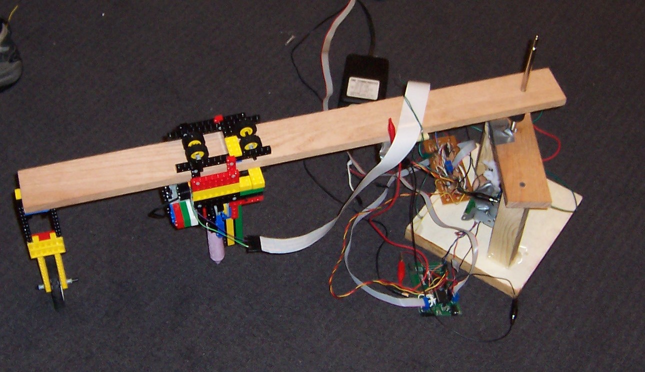
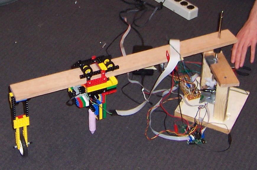
In the radial plotter design, a fixed base supports a rotating arm. A cart holding the pen moves along the length of the arm. The cart includes an up-down track to engage and disengage the pen from the drawing surface. The control maps directly to polar coordinates: the rotation of the arm is theta, and the distance moved is r.
The radial design has advantages over the other designs in both design and utility. The fixed portion can be just the center base, which can be much smaller than the fixed parts of a Cartesian system. It also only needs one arm instead of two. Also, the fixed positions allow for a much higher precision than the robot option. Finally, the final product can be easily scaled to mark a larger area by replacing one pulley and one plank with larger variants.
The only relevant math is the transformation from rectangular to polar coordinates. This was accomplished satisfactorily for us by the polar coordinate filter plug-in included with The GIMP.
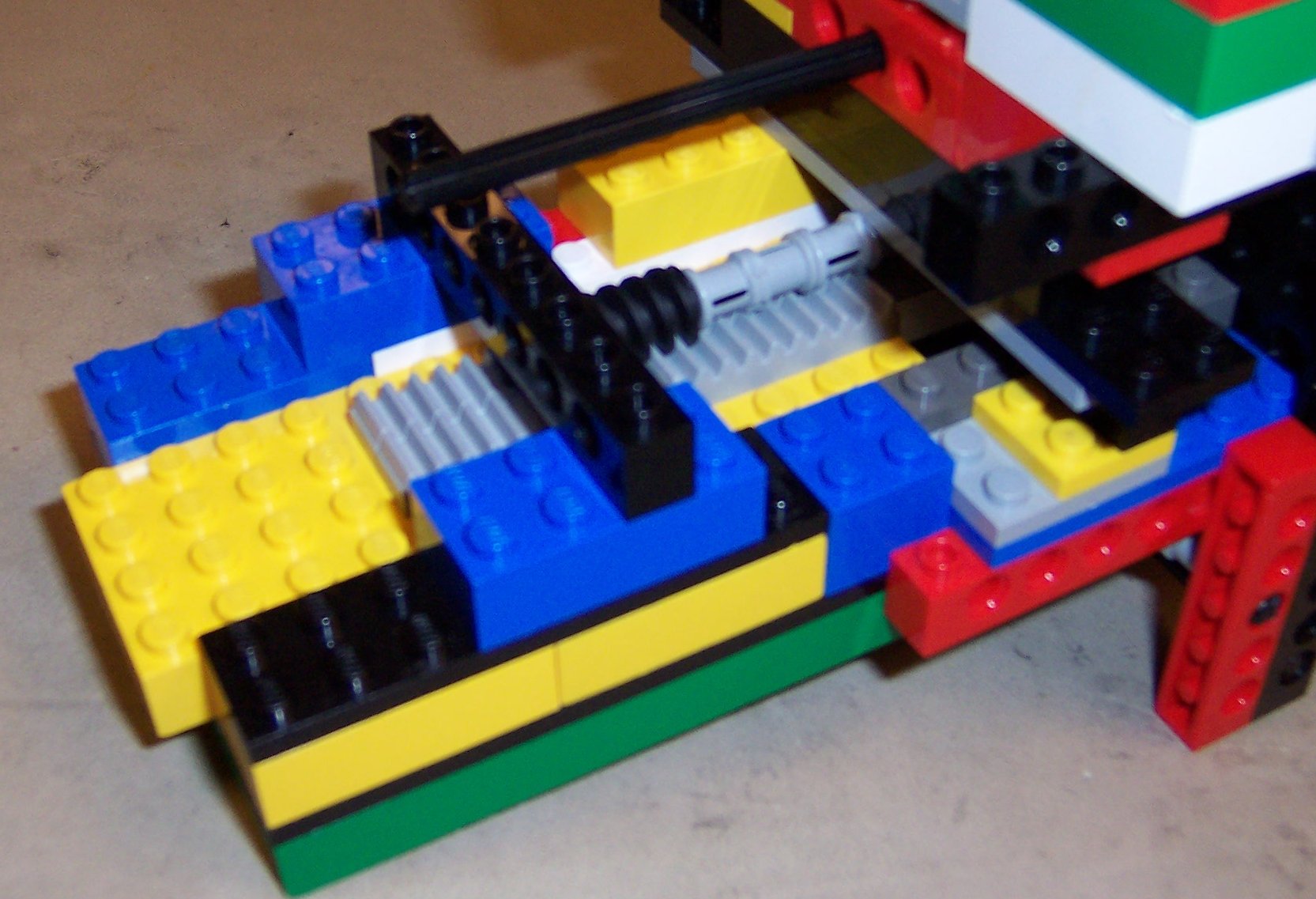
The challenge for designing the base is that it needs to support the fragile theta motor in an orientation different from one one it was intended for. The design problem was to impede all directions of movement except for the rotation necessary. A big hurdle was that the side we were using for a bottom could not rest on a flat surface without damaging the opto-reader disk. Our original idea was to use a stone-henge type setup where the top would have a hole in it and a stopper on either end of the hole would keep it suspended. The new problems this brought up were how to keep the theta motor from rotating itself, what to make the leg supports from, and how to attach the rod to the top part without impeding spin. We decided on wood for the leg supports, but our initial design could not solve the other two requirements. Our solution was (upon suggestion from John Son, another 476 student) to screw the metal piece that holds the motor and optical reader together directly to the leg support. This solved the problem of how to prevent the theta motor from spinning itself and we no longer needed to keep it suspended. We still keep the top and other leg pieces of the stone-henge structure to support the motor and have a rubber band that supports the non-screwed in side of the motor assembly. We then screwed the legs to a wooden base-board for further stability. The screws that attach the wooden base-board to the legs were countersunk with a Dremel® to maintain the levelness.
The theta motor and opto-reader control the theta movement of the chalker. It is the motor/optical reader from the paper-feed of the printer. We liked it for its precision (1800 ticks per rotation) and the fact that it already had a reasonably powerful DC motor included in the assembly. Unfortunately, it was not designed for the orientation in which we used it, so it is fragile, and a lot of planning of the superstructure design went into engineering around it.
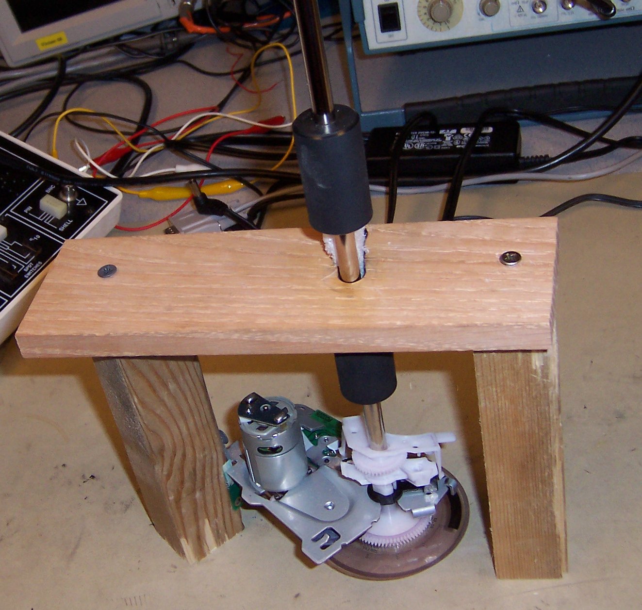
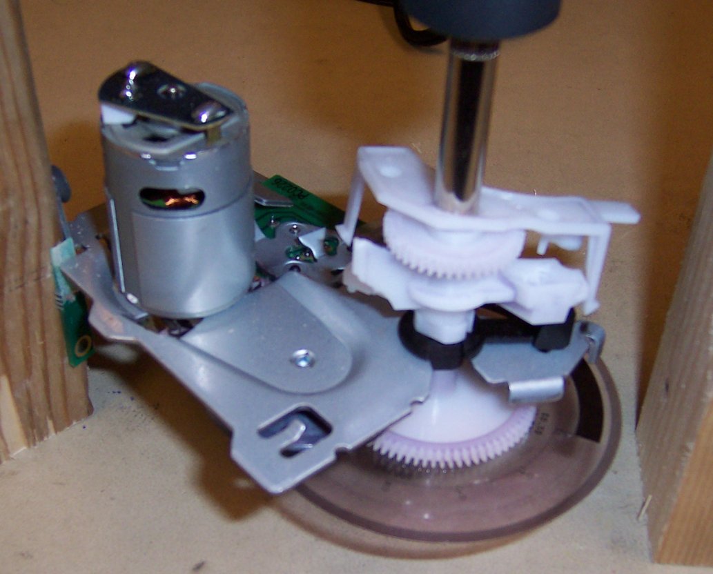
(The images above are from before construction was complete. A rubber band was added to add vertical support, and a wooded base was attached beneath to add stability and rigidity. The final structure is visible in the pictures of the final structure.)
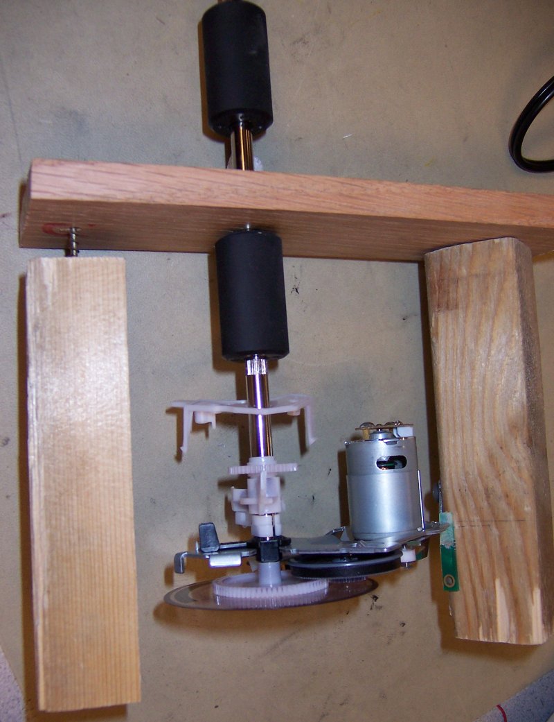
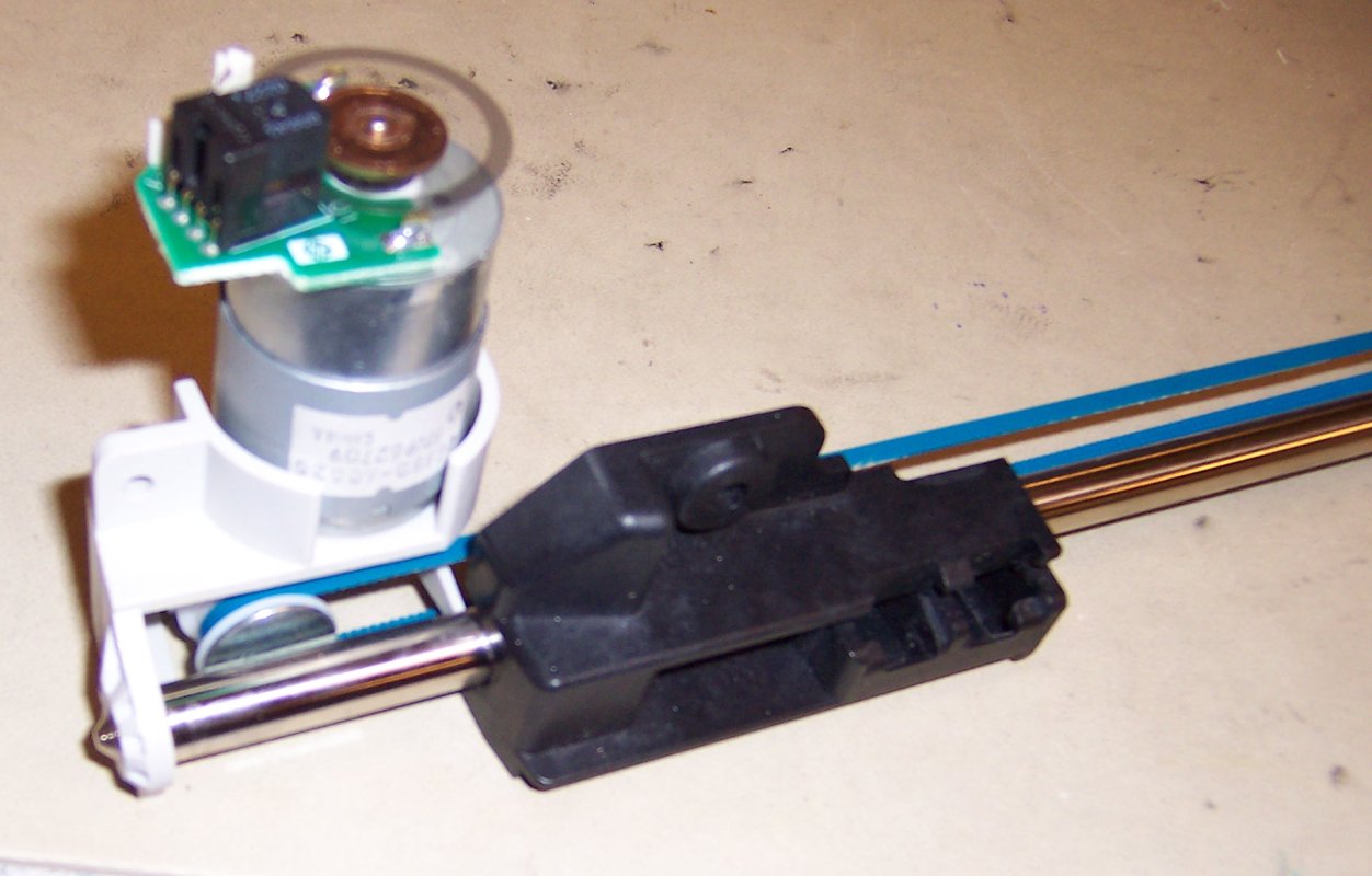
This unit needs to move the chalk over precise distances of the arm. One of us envisioned a device that slid like the track of a silverware drawer with the pen fixed at one end. The other envisioned a trolley that would roll along the top of the arm and hang a pen below. Inside the scanner was the perfect solution. We found a motor/optical reader that rotated a toothed tread around a pulley. The tread moved a plastic cart along a metal support bar which was meant to move the scanner under the paper. We removed the entire assembly from the scanner and suspended it under the plank. We attached a trolley that rolls along the top to the plastic cart with LEGO® bricks. The trolley design is described below.
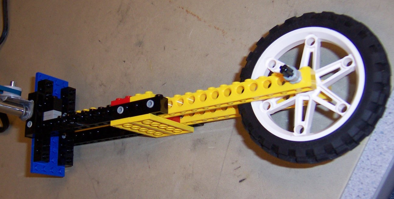
The radial motor and optical reader we use is from the scanner positioning assembly from our HP OfficeJet. It moves the chalk radially along the plank into position for up/down movement. It has precision of ~250,000 ticks over the reach of the plank.
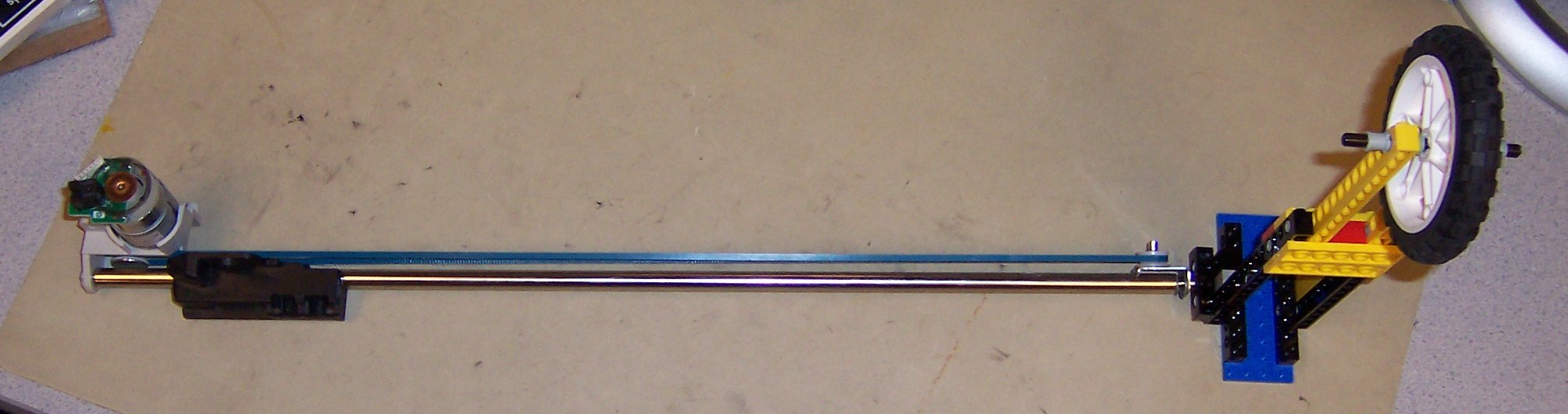
We use an oak plank of wood for our radial arm. Deciding on it took a surprising amount of planning. We initially intended to use a ~12 pound aluminum U-bar. After getting our donated HP officejet we realized using such a heavy bar with our limited power motors was unrealistic. Looking for a new arm we made a list of what we liked about our aluminum bar and what we didn't like about it. We liked having a U-shape to hide a shaft for radial movement and we liked that it was sturdy and rigid. We decided to use a PVC pipe with a square cross-section that we could cut in half long-ways. Unfortunately, our resources offered things that were either not u-shaped (planks of wood) or not rigid (gutters). After dissecting the scanner and discovering our radial movement system we decided on a wooden arm. The wood had to be wide enough to allow a trolley to roll along the top and long enough for the full extension of the radial system. The plank is 26"x4"x.5". We chose Oak for it's rigidity. Because of it's rigidity, holes needed to be pre-drilled for any screws.
This component is made from a LEGO® Mindstorms™ set. Less abstract design was needed for this component because the size and shape of the trolley were predetermined by the size, shape, and height above ground of the plank. However, more iterative design and construction was required to build a component that met the size, functionality, and rigidity requirements. The motor is a geared-down 12V LEGO® motor that rotates a shaft with a worm gear attached to a rack and pinion for linear movement of the pen (up/down control). We used a worm gear to increase the amount of power the motor could apply to the pen and for the way it fit in with the rest of the trolley structure. The trolley fits around the plank and has wheels that roll along the top of the plank. Its motion along the plank is entirely controlled by the scanner's sliding component (the 'cart') which it is attached to the scanner positioning assembly with a plastic LEGO® shaft. Since neither of us is especially adept at building useful structures with LEGO® bricks, we solicited the help of one Luke Whitlow, a local Ithacan. He made invaluable contributions to the sturdiness and functionality of the pen trolley and outer wheel.
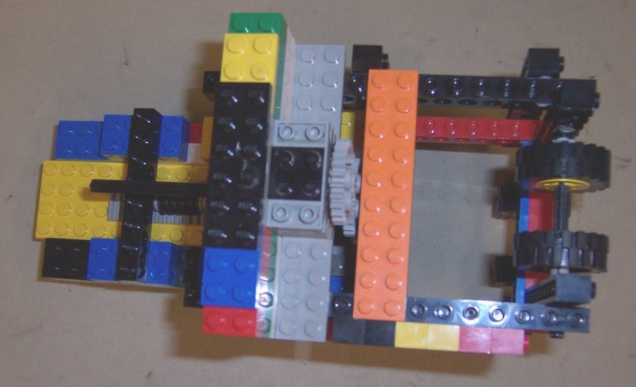
The wheel support on the end of the arm is made of LEGO®
bricks with a LEGO® wheel. The height allows for free
movement of the pen trolley under the arm and was designed with
the height of the theta motor's shaft in mind. The wheel support
is attached to the underside of the arm with hot glue, and
attached to the radial motor shaft using a LEGO® brick
modified with a Dremel®.
Our biggest trade-off between hardware and software were caused by the limitations of the parts we could scrounge. The most significant example is the use of DC motors for positioning. The printer/scanner that we found used DC motors, so we were faced with the choice of using them as-is or replacing them with stepper motors. Since stepper motors theoretically give precise positioning information based on the number of steps taken, they are easier to control. However, we opted against switching to stepper motors because they have less resolution and we would have had to re-engineer the assemblies.
An H-bridge built just out of transistors as switches would
usually rely on software controls to ensure that there is never a
connection between the positive supply and ground. However, we
found full bridge chips that had the necessary logic included in
the chip, so the software only had to control direction
lines.
Also, we could have purchased full motor drive packages that
include current control and even possibly the position feedback.
Instead, we approximate current control by several PWMs done
completely in software.
We know of no standards relevant to this project, since our project does not communicate with any other devices. The only interfacing we performed was with power supplies, motors, and optical encoders. We reverse-engineered the simple interface to the optical encoders.
Regarding overall design, we know of no relevant patents, copyrights, or trademarks relevant to this project.
We were careful in this report to use the LEGO "Fair-play" legal requirements. Also, the following trademark disclaimers apply:
The following sections describe the components from the point of view of the electrical and electronic interfacing required.
Both the r and theta motors are attached to optical position encoders. Both consist of a transparent disc with micrometer-scale lines printed along the edge. The disc is attached to the rotating assembly so that the microline pattern rotates. A red LED, fixed at the edge of the disc, shines through the microlines onto two light sensors. The outputs of the light sensors change as individual lines pass between them and the light source. The lines and detectors are arranged such that the output is "quadrature encoded". That is, the sequence for the two sensor outputs is 00, 01, 11, 10, 00, etc. If the motor direction is reversed, the sequence reverses as well. So the sensor inputs enable the controller to track the amount of rotation, including direction, with a high degree of accuracy. The theta encoder, linked directly to the rotating arm, has 1800 lines along its edge, so it specifies rotation to half-degree resolution. The r motor is heavily geared down, so the shaft spins many times more than the moving mechanism. Despite the much smaller wheel size, the high gear ratio results in around 250 thousand counts while the cart travels from one end to the other. This extreme resolution is exactly what was required for the high-resolution scanner that it came from, but it posed an interesting problem for the microcontroller, as discussed later.
We used the original main board of the printer/scanner to help reverse-engineer the electrical interface to the optical encoders. Most importantly, manually supplying power to the mainboard allowed us to determine which pins were connected to 5V supply and ground. To re-interface these components to our board, we cut the existing connectors (after carefully noting the pin order) and attached two-pin headers that can plug directly either into the STK500 development board or directly into port pins on our target board. Choosing a design that would work equally well on both boards proved very valuable in testing. Also, the solderless connections on the headers were very reliable.
Interpreting the optical encoder output is simple: on the positive edge of the first input, either increment or decrement the count depending on the value of the second input.
Since the optical position encoders only provide relative positioning information, at startup the controller has no way of knowing the current r and theta position. It can safely assume that the starting angle corresponds to a theta of zero, since there is no preferred angle. However, it cannot make any assumptions on the current r position, since the cart has a bounded range of motion. A limit switch positioned at minimum r provides the needed absolute position reference. When the cart hits the limit switch, the controller can know that the current r position is at its minimum, and can use that as a zero reference.
The design of the limit switch included a surprising consideration. The basic idea was that the switch would be connected between a port pin and ground; the internal pull-up resistor on the port pin would normally keep the input high, but when the switch closed, it would pull the voltage low. We were going to use a LEGO® touch sensor for the switch, but discovered only after fully wiring it up that the internal resistance of the switch was too large to pull the input down. We had to substitute a pushbutton that we found.
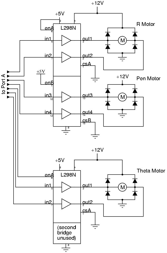
All 3 motors that we used are DC motors. Their electrical interface, as far as this project is concerned, is fundamentally very simple. At a given input voltage, the motor will attempt to spin its shaft at a given speed. The motor windings serve as inductors, suggesting that a pulse-width-modulated signal can substitute for a varying voltage. The main difficult component about DC motors is that in order to reverse the direction of the motor, the direction of the current must reverse. However, the bridge driver circuits provide a simple interface for the microcontroller: pulling one control line high makes the motor spin in one direction, the other the reverse direction, and the two identical (high or low) make the motor brake.
The pen control also uses a DC motor, but with more specific requirements. When putting the pen down, it needs to maintain downward pressure on the drawing instrument, but it only needs to move up a small amount to pick the pen up. This requirement makes the control logic for the pen motor slightly more complex, as described later.
There is a separate circuit board that all subunits connect to
witch houses all the motor driver circuitry. This board includes
machine headers that can connect to an STK500. We intentionally
did this separately so in case our microcontroler board failed in
the course project, an STK500 can easily replace it. It also lets
us use an STK500 during testing, which is much easier interface
with and program.
In the appendix are the circuit designs for a single motor
control and the full solder board design including three motor
controls.
The goal of the microcontroller program is to control the motors in such a way as to draw pictures, using the optical encoders as position feedback. The following description of the parts of the program roughly follows the order of the program listing.
As noted above, the r optical encoder is extremely high-resolution. So moving the motor at any reasonable rate generates a very fast pulse train, with pulse durations as short as 50 microseconds. With a main clock of only 16 MHz, running a timer fast enough to consistently detect the rising edges would take most of the CPU time. Fortunately, the Mega32 includes configurable external interrupts, which work perfectly in this application. We set the interrupt to fire on the rising edge of the first optical encoder output, and in the ISR either increment or decrement the count according to the value of the second optical encoder output. Testing shows that while even a very fast timer missed many counts, no counts are ever missed with the external interrupt.
The theta encoder, with its lower pulse train speed, does not need an external interrupt, though we designed the system so that we could use one if necessary. Instead, the theta position is tracked by a timer interrupt running every 250 microseconds. Like the r position ISR described above, it updates the count on the positive edge of the first optical input. The same interrupt also checks the r limit switch. Upon activation, the limit switch stops the r motor and calibrates the r count to zero. This is important in the initial calibration in the main loop, described later. There is no need to debounce the switch since there is no harm in resetting the position count several times.
Timer 2, running every millisecond, implements three PWMs according to the motor state. The r and theta motor state is encoded straightforwardly as brake (motor leads shorted), positive, or negative, with the sense of positive and negative matching the directions that the position counters change when the motor moves in that direction.
However, as noted above, the pen motor may need to be pressing down on the pen, picking the pen up, or holding the assembly fixed in the pen-up position. To handle this, a single byte encodes the complete state. The maximum value (255) indicates that the pen is down, so the motor will be pressing the pen down. Smaller values indicate that the pen is moving up, until 0, which represents that the pen up motion is complete. If the pen is moving up, the value is decremented each complete PWM cycle, and the motor is turned off when the value reaches zero.
The initialization code, called on microcontroller reset, sets up the microcontroller as required by the rest of the code. Port A is used entirely for the motor control outputs; ports B and D are used for various types of inputs. Two of the connections to port B go to a switch, whose state is detected by setting one port to input with pull-up and the other to output low; when the switch is closed, the low output pulls down the high input. The switch internal resistance must be smaller than the internal pull-up resistance in order to pull the pin down; this proved to be a design concern, as discussed above..
After the microcontroller initialization is complete, the program then sets about putting the mechanical system in a known state. The pen could have been down, so the system first pulls the pen up, enabling subsequent free motion without drawing anything. More importantly, the pen cart could be anywhere along the arm, and since the optical encoder only gives relative position, there is no a priori way to determine its position. We considered saving the last known position in EEPROM, but that has considerations of update speed, long-term accuracy, and state desynchronization. Instead, we added a limit switch at the near end of the radial track. Then when the controller initializes, it puts the r motor into a slow negative motion and waits for the limit switch to close. When the limit switch closes, the radial position is at its lower limit, so it resets the count to 0 and stops the motor.
The main loop is divided up into two sections: the drawing control and the feedback control system.
We implemented two different drawing strategies: raster scan and path scan. Raster scan is the simplest to explain: the theta motor moves back and forth between its upper and lower limits, advancing the r motor by one step each time it reverses. Every position is mapped into a point in an (up to) 256x256 "pixel" array (r by theta, packed 8 theta pixels per byte, stored in Flash memory). If the current position is within a pixel that is on, the pen is pushed down, otherwise it is pulled up. This system is very simple to implement, requires only one feedback control (for the r position), and can easily draw arbitrary pictures. However, performance on line drawings is poor, since they take overly long to draw and become pixelated.
The other method we implemented is a path scan. An arbitrary path can be drawn by following a sequence of points (r, theta, pen). Pen is a flag that indicates whether the pen is down while moving to that position. A complex control system could attempt to follow a smooth curve defined by the given point sequence, but we opted for a simpler system: advance to the next point after getting to the current point. Since the optical position encoders are so precise, a threshold value is used to indicate that the position is close enough to the desired result to go on to the next point. The points are stored as structures in an array stored in Flash; a special value of pen (255) indicates that the drawing is complete. With the simple control system, the points might not be connected by straight lines in r-theta space; if more accuracy is required, more points may be used.
In both cases, the pattern to be drawn must be given in polar coordinates. No coordinate transform is performed on the microcontroller, since it is more easily done on a computer, and the results may be visualized before chalking. In both cases, when the drawing is completed, the controller stops the motors and enters an endless loop to halt execution.
The optical encoders provide an accurate read-out of the current position. The motor controls and PWM provide a means to move the motors at selected speeds in either direction. The responsibility of the feedback control system is to use the information about the current position to determine a motor speed and direction that will move the system to the desired position. Arbitrary complexity can be introduced in the feedback control through accurate models of the system response, but we chose to keep this simple unless testing determined that a more complex system was required. The drawing control routines provide goals for the r and (in the path control case) theta positions; the interrupts provide the actual positions in terms of microline step counts. The feedback control system computes the position error as the difference between the desired and actual positions. It determines the motor direction based on the sign of the error. If the position error is bigger than a threshold, it sets the motor to maximum speed, otherwise it divides the error by a constant to determine the speed. The resulting system is a simple first-order feedback control, but it is moderately nonlinear due to the maximum value of the motor speed. Testing did not show the need for a more advanced control system, as long as the threshold and constants were set correctly.
The raster scan method only requires one feedback control: when one sweep in theta is completed, the r motor needs to advance by exactly one step. The path scan method requires feedback control on both axes. There is no feedback available on the pen motor; in hindsight, a current-sense controller would have been useful to maintain a constant downward force on the pen.
Independently, each of the components works, and was thoroughly tested. However, as we had been concerned about since the beginning, the theta motor proved too weak to rotate the arm when it had to drive the full weight of the beam. It had performed acceptably under our simulated loads, however, so we suspect that the power supply was also not strong enough to provide the full required current to all components simultaneously. Extra resistance in some of the solder joints in the motor drive board could have also contributed to this; it was very difficult to get good connections to the traces on the board, which often separated from the board itself under the heat of the soldering iron.
Our backup plan was to use our second LEGO® motor as the theta motor and position it on the outside wheel for more torque. A lack of time prevented us from implementing this plan, before the project demo, but it will be our first step if we try again to get it to work. We would also seriously consider rebuilding the motor drive circuit on a more reliable board, or being much more careful in soldering it to avoid traces falling off.
While the poor performance of some small pieces caused the integrated design not to work, we still consider the design a success because the design was good, all of the many components work well individually, and everything except the theta motor worked when integrated.
This was a very ambitious project from the beginning, and we added additional adventures for ourselves along the way. As far as we know, the idea was completely new; we have never seen an existing polar plotting system, and there is no existing structure or design that we could have used as a model. We might not have chosen to do this project if we had fully realized how involved it would have to be.
One of the big decisions was to scrounge old motors and optical encoders instead of buying them new. While this made some parts of the project easier, it made others much more difficult, especially the theta motor. If we had instead designed and built the assemblies ourselves, the overall project may have taken less time, though definitely at greater cost.
While the polar design was new and very interesting, we may go with an alternative design for practical implementation. The problem with the idea of using a RC car platform is that positioning is very difficult. However, we found some very accurate positioning devices literally right under our hands. Using two of them, possibly in conjunction with a GPS system, would provide the accurate positioning needed. Writing the control system would be a challenge, though. But the sight of a little car driving around campus and writing on all the sidewalks might make it a challenge worth taking.
There are no applicable standards.
Using the assemblies from the HP printer/scanner does pose a potential intellectual property consideration. However, we consider this project a prototype; if it were actually to enter production at any scale, we would not use the printer components at all, but rather build our own components to our own specifications.
All of the code is written from scratch for this project. There were no existing overall designs that we could have used if we had wanted to. We did use the HP printer/scanner components, and hence used their design, but the overall structure and how we used the printer components is completely our own.
We reverse-engineered parts of an HP OfficeJet D135 printer/scanner combination unit. However, we do not expect there to be any patent/trademark issues since the components that we used were of a design that is common to most such devices.
We did not sample any parts.
We have not seen any other radial plotting system, and a rough patent search yielded no applicable patents, so we could explore patent possibilities with this design.
From the IEEE Code of Ethics:
There are no applicable legal or regulatory considerations associated with this project.
We would like to thank the following people for their contributions to our project at crucial times:
chalker-unified.c: Unified
raster and path drawing coderaster.h: A raster
bitmap to draw Bruce Land's head in chalk.path.h: A simple example
path control file.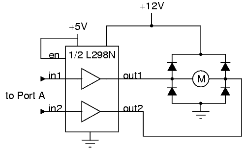
| component | cost |
| solder board | $2.50 |
| ATMEL ATMega32 | $8 |
| last year's custom PC board for Mega32 | $2 (no serial link) |
| oak plank from Lowe's | $5 |
| 3x L298N Dual Full Bridge driver | 3 x $3 = $9 (but we only used 2) |
| total budget | $26.50 |
| component | source |
| LEGO® bricks and motors | from a Mindstorms® set that Ken has owned for years, augmented by some random pieces from another old set and some of Luke's collection |
| radial motor and optical reader | from the HP OfficeJet scanner's scan head positioning system |
| theta motor and optical reader | from the HP OfficeJet printer's paper feed assembly |
| power supply | found abandoned on the Phillips Hall loading dock |
| duct tape | borrowed from Ken's roommate |
| miscellaneous pieces of wood | found behind Rhodes Hall |
| wood screws and use of power tools | donated by Luke |
While both of us contributed in some way to every part of the project, some parts of the project were handled more heavily by one or the other of us.
Tasks divided almost equally: