Air Hockey 3D
A two player air hockey video game with non-contact paddles
by Ching Yu Henry Yip (cy68) and Zhengpeng Chen (zc35)
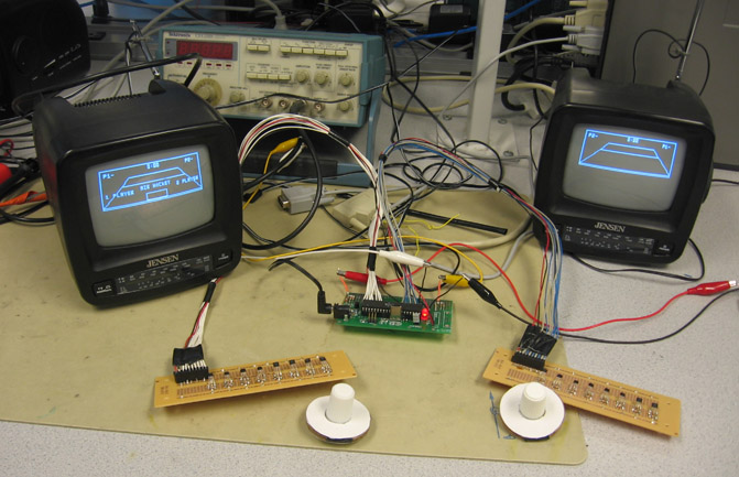
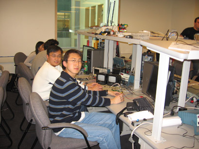
Above: The final set-up showing the prototype board (center), Hall Effect sensor arrays (bottom left and right), paddles, and television sets.
Our final project is a two-player, 3D, air hockey video game using non-contact paddles.
A single Atmel ATmega32 microcontroller on a prototype board is used to compute puck dynamics, decode inputs from two Hall effect sensor arrays, compute paddle-puck interactions, perform perspective projections from 3D to 2D for each player, and generate two different video signals. Two television sets are used so that each player can see the playing field from the player's own end, with a three-dimensional perspective. Each player can see his or her own paddle, together with the opponent's paddle and all paddle movements. The players control their paddles using Hall effect sensor arrays, which do not require contact and are frictionless. The video signals are in NTSC format at 60 frames per second (interlaced). The various calculations are optimized so they will not affect video signal generation, preventing artifacts from appearing on-screen.
The actual air hockey game requires an air hockey table, two paddles (or mallets), and a puck. A typical air hockey table consists of a large smooth playing surface, a surrounding rail to prevent the puck and mallets from leaving the table, and slots in the rail at either end of the table that serve as goals. On the ends of the table behind and below the goals, there is usually a puck return. Additionally, tables will typically have some sort of machinery that produces a cushion of air on the play surface, with the purpose of reducing friction and increasing play speed1. This aspect is recreated in the game by not having any drag on the puck movement.
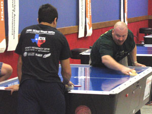
Above: Air Hockey game featuring Danny Hynes, current World Champion. Picture from Wikipedia1.
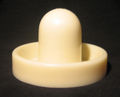
Above: Actual Air Hockey Paddle (or Mallet). Picture from Wikipedia1.
Overview
The program design and in-game transitions can be summarized with the following block diagram:
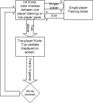
Above: Block diagram showing high-level design of the program.
State machine
A state machine was created to implement the high-level design shown above. This state machine provides a choice between 1 and 2 player modes. It also pauses the game after each point and set, so as to show who scored. A victory screen is also displayed when a player wins 3 sets. Subsequently, the game returns to the initial start-up screen.
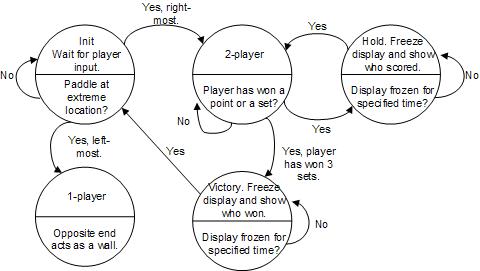
Above: State Machine. 16.67 ms transitions.
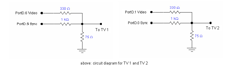
Driving Two TVs with Interlacing
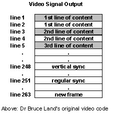
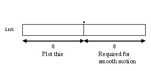
Dr Bruce Land’s video code, which writes every line in the video buffer array twice at 60 frames per second, is modified to drive two TVs with two different contents. The figure below shows the line sequence of each frame in the original code:
We take advantage of the redundancies in the line sequence to add in contents for another TV. The motivation behind this is that, NTSC format, consisting of only 30 interlaced frames per second, is still able to generate video without flickering. By using a similar arrangement of line sequence, we are able to drive 2 TVs at 30 interlaced frames per second using the arrangement below:
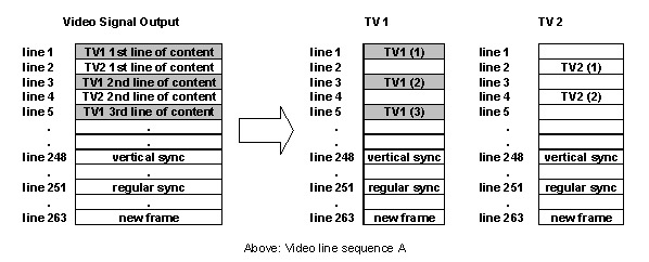
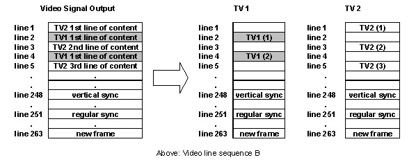
Video line sequence A and B alternates to gives 30 interlaced frame per second for EACH of the two TVs. In the code, video line sequence A is given the value 1, and sequence B the value 0. At each interrupt (beginning of each video line from line 1 to 263), the micro-controller outputs to TV 1 (via PORT D.5 and D.6) if it is at an odd line in video sequence 1, or at an even line in video sequence 0. Otherwise, it outputs to TV 2 (via PORT D.0 and D.1).
Two video buffer arrays are used to store the contents for the two TVs. With only 2kb of SRAM, we have to limit the size of our video buffer to 800 bytes each. This still gives a reasonably sized playing area. Basic drawing tools such as videoline(), videopt(), videoputsmalls() are duplicated to allow us to edit the other video buffer.
[back to Program/Hardware Design]
Perspective Projection2
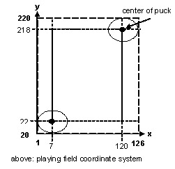
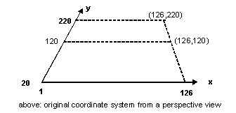
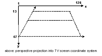
The perspective projection corresponds more closely to the way a human observer perceives a 3D scene: objects far away appear smaller and closer together. Mathematically, the projection transformation converts a point (x,y,z) into (x', y'), the image point where the 3D point appears on the output medium (TV screen). The figures below show how the 2D playing field used in our puck dynamics calculation would look like in the perspective projection. The ultimate goal of the transformation is to convert the playing field coordinate system into each player's TV screen coordinate systems.
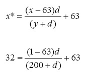
To begin the transformation, let's consider the simple scenario where the viewer is at the origin, and the plane of projection is at z=d. The original coordinates (x,y,z) will be transformed to
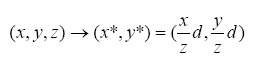
When the viewer is not at the origin, all we need to do is a simple translation. In our code, the x-axis of the playing field coordinate system is aligned with the x-axis of the TV screen coordinate system. The center of screen is at x=63, and this gives the x-coordinate of the viewer.
We next determine how we want the 200x126 air hockey table to look like on the TV screen. We decided that the far end of the air hockey table should look like it has half the width of the near end, while the length of the table must fit from y=13 to y=47 on screen. This allows us to find the value of d. Intuitively, we are asking the question: from how far should we view a 200x126 table such that its far end appeared as only half its near end?
One equation can be formed by looking at the projection of far left corner of the table with coordinate (x=1,y=200) (*To keep projection simple, the length 200 playing field runs from y=0 to y=200 instead of y=20 to y=220 used in dynamics calculation). The far left corner appeared on the TV screen at (x=32, y=13). The equation below is solved to yield d=200.
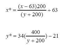
The equations of projections from the playing field coordinates to the TV screen coordinates for Player 1 are found to be:
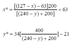
To view the playing field from the other side of the air hockey table, a similar transform can be applied. We can use the same coordinate system from Player 2's perspective by performing a reflection about x=63 and y=120.

The equations of projections from the playing field coordinates to the TV screen coordinates for Player 2 are found to be:
To summarize, we perform the puck dynamics calculation on the playing field coordinate system. The position of the puck obtained at the end of each video frame is then displayed at the appropriate position on each player's screen using perspective transformation. This gives both players the perception that they are watching the air hockey table from their own side.
[back to Program/Hardware Design]
The puck has an x and y position variable, an x and y velocity variable, and an “age” flag. The “age” flag keeps track of whether the puck has entered a goal, i.e. not returned by a player. When a new puck enters into play, the “age” flag is initialized to 1. The flag is set to 0 when any player fails to return it. Thus, the puck is removed from the game and not displayed. Subsequently, a new puck is initialized.
[back to Program/Hardware Design]
Fixed point
arithmetic is used here for positions and velocities, because animation involves
fast loops and floating point arithmetic is too slow for small, 8-bit processors
to handle, except when human interaction is involved. Fixed point representation
uses numbers stored as 16-bit
signed ints,
with the binary-point between bit 7 and bit 8. This allows a dynamic range of
+/- 127,
with a resolution of
1/256=0.00396.
Sign representation will be standard 2's complement.
Above: Fixed point representation.
Dr. Bruce Land provided macros to perform type conversions, multiplication, and division. He also wrote an assembler function call for multiplication that provides a significant speed increase over the original macro version. A macro to perform fixed point absolute value was already written for homework 4. Addition and subtraction were performed using the standard C operators. The division, square root, sine, and cosine functions were not used in order to optimize the code. Fixed-point division was performed by shifting the bits right.
Video content beyond the playing area was removed to provide more time for computation. When the scan line is beyond the visible playing area (line 131-line 262), the interrupt only outputs a 4.7μs horizontal sync pulse. That allows computations to be carried out without visual distortion on the screen.
[back to Program/Hardware Design]
Puck collisions are carried out by calculating the total change in velocity from a collision, without worrying exactly how forces change the velocity. The change in velocity during impact between a frictionless puck and the wall can be derived by noting that the impact force must act in a direction perpendicular to the wall surface. Collisions with the left or right walls are detected, and the velocities are modified by negating the velocity component perpendicular to the wall. The paddles are depicted as flat surfaces on-screen and behave the same way as a wall when the puck collides with them. The difference is that the paddles have a horizontal velocity and can impart it to the puck. In this program, velocity is scaled so that we can make dt = 1 when performing calculations, thus avoiding more multiplication operations.
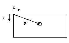
Above: Position vector of the puck.
[back to Program/Hardware Design]
In the two player game mode, a player scores when the other player fails to return the puck. The puck is then said to have entered the goal. For example, player 1 hits the puck to player 2, who cannot return it. Player 1 scores and his or her point total is increased by 1. The first player to win 7 points wins a set. The first player to win 3 sets wins the game.
In the one player training mode, player one can hit the puck and the top, left, and right sides act as walls. Player 2 is free to move his or her paddle, but has no effect on the puck.
[back to Program/Hardware Design]
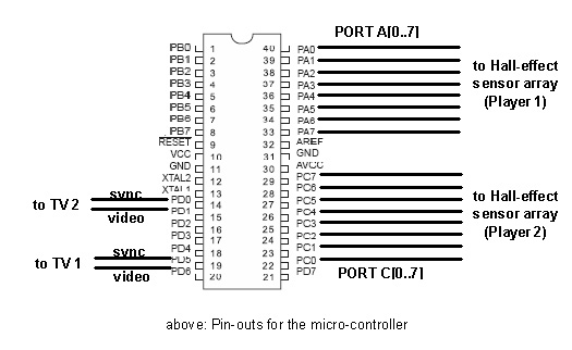
Each player controls the in-game paddle using an array of Hall effect sensors. Each array is soldered onto a solder board. The player holds the paddle above the array and can move left or right. The in-game paddle moves according to the player's actions. No contact is needed because the sensors measure magnetic field strength. The following diagram illustrates the hardware connections:
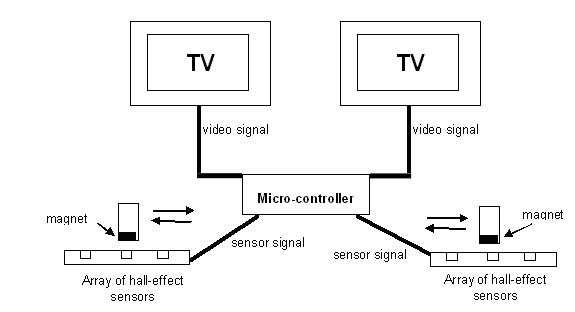
Above: Overview of hardware connections.
Eight of the Allegro A1101-EUT and A1101-EUAT Hall Effect continuous time switches are used to construct one array, while another eight of the A1102-EUT and A1102-EUAT switches are used to construct the other. All sensors were sampled from Allegro. The A1101 sensors are slightly more sensitive because of their lower hold and release thresholds. The EUT and EUAT labels refer to the 3-pin SIP package for through-hole mounting (the EUAT is smaller than the EUT, but both are otherwise identical). Each package is lead (Pb) free.
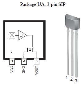
Above: The Allegro A110x family of Hall Effect switches, in the 3-pin SIP package. Diagram from Allegro A110x Continuous Time Switch Family datasheet.
According to the Allegro datasheet, the A110x family, produced with BiCMOS technology, consists of devices that feature fast power-on time and low-noise operation. These switches include the following on a single silicon chip: voltage regulator, Hall-voltage generator, small-signal amplifier, Schmitt trigger, and NMOS output transistor. The integrated voltage regulator permits operation from 3.8 to 24 V. In our case, a 5V supply is used. The regulator is also stable without a bypass capacitor.
The output of these unipolar devices switches low (turns on) when a magnetic field (south polarity) perpendicular to the Hall sensor exceeds the operate point threshold, BOP. After turn-on, the output is capable of sinking 25 mA and the output voltage is VOUT(SAT). When the magnetic field is reduced below the release point, BRP , the device output goes high (turns off). The difference in the magnetic operate and release points is the hysteresis, Bhys, of the device. This built-in hysteresis allows clean switching of the output, even in the presence of external mechanical vibration and electrical noise.
Above: Actuation of Hall Effect sensor, using a magnet's south pole.
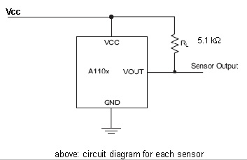
A circuit is set-up as shown in panel B below for each Hall Effect sensor so that it behaves as a digital switch as described in the paragraph above.
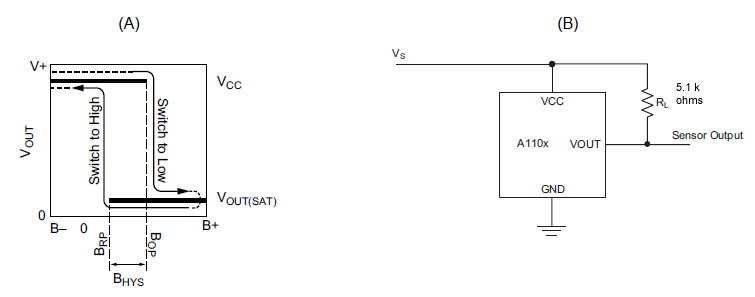
Above: Switching behavior of unipolar switches. On the horizontal axis, the B+ direction indicates increasing south polarity magnetic field strength, and the B– direction indicates decreasing south polarity field strength (including the case of increasing north polarity). This behavior can be exhibited when using a circuit such as that shown in Panel B. Diagram from Allegro A110x Continuous Time Switch Family datasheet.
Eight of these circuits are constructed on a solder board to form an array. When a magnet is directly above a sensor, only that sensor will turn on. If the magnet is in between two sensors, then both sensors will turn on. By doing so, a total of 15 possible magnet positions can be determined.
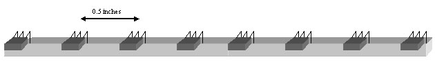
Above: Schematic of Hall Effect sensor array. Each player will use one such array, with a total length of 3.5 inches.
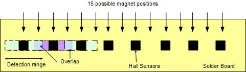
Above: Diagram showing how 15 magnet positions can be determined by using the overlap in detection ranges of the Hall Effect sensors.
By using these 15 positions, paddle movement across the screen is smooth and the on-screen paddle can be of a reasonable size that is sufficient to block a puck coming from any direction. If there were fewer positions, then the on-screen paddle would have to be quite large in order to block all possible shots.
The signals from the sensor array corresponding to the magnet positions are shown below. The eighth bit of the array output (left-most bit) is the output from the left-most sensor. The seventh bit corresponds to the sensor that is second from the left. The right-most bit corresponds to the right-most sensor.
| Magnet Position | Sensor Array Output |
| 1 (left-most) | 01111111 |
| 2 | 00111111 |
| 3 | 10111111 |
| 4 | 10011111 |
| 5 | 11011111 |
| 6 | 11001111 |
| 7 | 11101111 |
| 8 | 11100111 |
| 9 | 11110111 |
| 10 | 11110011 |
| 11 | 11111011 |
| 12 | 11111001 |
| 13 | 11111101 |
| 14 | 11111100 |
| 15 (right-most) | 11111110 |
Above: Sensor Array Output corresponding to magnet positions.
The signals are digital and do not require the microcontroller's analog-to-digital converter (ADC). Instead, the signals are connected directly to the microcontroller's port pins.
The actual set-up and paddle are shown below.
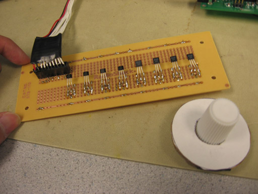
Above: Hall-effect sensor array and paddle.
[back to Program/Hardware Design]
The paddle has a horizontal velocity and can impart it to the puck. During initial testing, we experienced difficulty in imparting velocity to the puck. There was either no velocity imparted, or too much was imparted and the puck moved too quickly. We needed a more reliable algorithm for paddle-puck interaction. The original algorithm was to calculate paddle velocity by the change in its position from the previous frame to the current frame. However, a frame is only 16.67ms and the paddle very often does not move during that interval because the player is holding the paddle still to return the puck.
Our solution was to create a 10 frame moving average velocity calculator. The paddle velocity is calculated for every frame, and is stored in a ten-element array. When all elements are full, the velocity is then stored from the first element onwards, overwriting the previous contents. When the program detects a collision between the paddle and the puck, the average velocity is calculated, shifted right by 6 bits (divide by 64), and is added to the puck's horizontal velocity. This method allows for more reliable transfer of velocity from the paddle to the puck, without the puck speeding up too much. Using a moving average ensures that the momentum of the paddle from previous frames is considered and not just its movement within a short interval of 16.67ms.
[back to Program/Hardware Design]
Portable Prototype board and controllers
In order to increase portability of the entire system, the wires linking the sensor arrays to the prototype board were not soldered to the solder board. Instead, we soldered SIP connectors to both solder boards, so that the wires could be connected or removed with ease. Doing so enhances the portability of the system, and allows for more convenience in transport and storage.
1. Speed of execution / Interactiveness
There is no observable flicker at a comfortable viewing distance of 2-3 ft from the small TV despite the use of interlaced video frames. Theoretically, we are using the same refresh rate as standard NTSC video, so video flicker should not be observed. There is also no video artifacts at all stages of the game. The projection transformation worked well as the puck is confined to the perimeter of the air hockey table, and the puck movements looked "natural" - the best indication that the perspective projection is implemented correctly.
The paddle movement on the TV screen is smooth as the actual paddle is physically moved through the array of Hall effect sensors. We find that the array with 1101 sensors are actually more sensitive than the 1102 sensors (which has higher "hold" and "release" thresholds). Due to budget consideration, we did not replace the 1102 sensors. Users can probably felt a difference in sensitivities, but both sensor arrays provide sufficient control for the players.
2. Accuracy
The video line duration from the video code is 63.625us while NTSC signal is 63.55us. No flickers are observed due to this 0.1% timing inaccuracy.
3. Safety
Neodymium magnet has a low-to-moderate acute toxic rating3. The commercial neodymium magnets used in our paddles are coated with stainless steel which prevents direct contact with the neodymium core. As the magnets are tiny (quarter-inch in diameter), they could be a choking hazard to children. Therefore, the magnet is glued tightly to the paddles and held in place by another embedded magnet to prevent it from falling out.
There is a possibility of shorting the 3 exposed legs of the hall effect sensors (Vcc, ground and Vout) with the magnet. While the current is not dangerously high given that Vcc is only 5V, we still want to prevent any short circuit from happening. The conductive magnet is wrapped with insulating tape and the whole sensor array is insulated by a thick cardboard enclosure. Individual legs of the hall effect sensors could be wrapped with insulating material to prevent them from touching each other if we were to build a commercial version of the game.
Individuals with pacemakers or internal medical devices should not handle strong rare-earth magnets magnets. Studies have shown that magnetic fields can affect the operation of these devices. Strong rare-earth magnets should be kept at a safe distance from individuals with these devices.
The hall-effect sensors that we used are lead-free, and are therefore safer for soldering and prolonged usage.
4. Interference with Other People's Designs
Since we are not using any RF transmitters, interference is not an issue. The rare-earth magnets may, however, destroy data on magnetic storage medium when placed in close proximity (a few inches).
5. Usability
Playing the air hockey game involved only simple paddle movement, which is suitable for players of all ages. The paddle is light and there is no direct contact with the sensors, so repetitive strain injury is unlikely.
1. Analysis
The two primary goals of our project are: Hall-effect sensor input and perspective projection. The results of this project successfully met our design goals and expectations. A few areas of improvement will be larger playing area (current playing area is limited by the 2kb of internal SRAM, so external SRAM is needed) and better in-game graphics with color. Our initial project specification called for implementing a difficulty selection. We were unable to add this extra enhancement because of insufficient time.
2. Conforming to standards
The video code follows the NTSC standard using 29.94 interlaced frames per second. Following the NTSC refresh rate and interlacing standards ensures that the video can be displayed properly on a NTSC-compatible TV. Our refresh rate is 60 frames per second and 262 lines per frame. ANSI C standards were followed when writing code for the project.
3. Intellectual Property Considerations
We modified Dr. Bruce Land's video code and based the puck dynamics calculation on Lab 4: Particle Beam. While there are many air hockey video games on the market, our concept of using magnetic paddles with Hall-effect sensor arrays as input device is original. The ability of the single micro-controller to support output to 2 TVs is also a unique feature of our game.
4. Ethical Considerations
We, the members of the IEEE, in recognition of the importance of our technologies in affecting the quality of life throughout the world, and in accepting a personal obligation to our profession, its members and the communities we serve, do hereby commit ourselves to the highest ethical and professional conduct and agree:
1. to accept responsibility in making decisions consistent with the safety, health and welfare of the public, and to disclose promptly factors that might endanger the public or the environment;
We research on the safety issues regarding the handling of rare-earth magnets. Strong rare-earth magnets should be kept at a safe distance from individuals with pacemakers or internal medical devices. We therefore advise individuals with such devices to keep a safe distance while playing our air hockey video game. Other safety issues (eg, choking hazard, possibility of short circuit) are addressed to the best of our abilities (refer to the section on Safety) to protect the safety, health and welfare of the public.
2. to avoid real or perceived conflicts of interest whenever possible, and to disclose them to affected parties when they do exist;
There are no real or perceived conflicts
of interest associated with the project. The use of Dr Bruce Land's video and
hard-ball dynamics codes are acknowledged in the section on Intellectual
Property Considerations.
3. to be honest and
realistic in stating claims or estimates based on available data;
The report states honestly the results of this
design.
4. to reject bribery in all
its forms;
No bribery is offered to our team members during
the course of the project.
5. to improve the
understanding of technology, its appropriate application, and potential
consequences;
Our report explains the application of relevant technologies with great details. We also provide references and spec sheets for those who are interested to know more about the technologies applied in our project.
6. to maintain and improve
our technical competence and to undertake technological tasks for others only if
qualified by training or experience, or after full disclosure of pertinent
limitations;
The project was a great learning experience for
both of our team members. Our technical competences are greatly improved.
7. to seek, accept, and
offer honest criticism of technical work, to acknowledge and correct errors, and
to credit properly the contributions of others;
We look into ways to prevent the magnet from shorting the legs of the Hall effect sensors after another student in this course commented on the issue. That led us to wrap the magnet with insulating tape and also make an insulating casing for the sensor arrays. By seeking and accepting criticism from others, we made our product safer to use.
Proper citation is given to the use of Dr Bruce
Land's video and hard-ball dynamics codes in our game.
8. to treat fairly all
persons regardless of such factors as race, religion, gender, disability, age,
or national origin;
No persons were treated unfairly during the course of this project.
9. to avoid injuring others,
their property, reputation, or employment by false or malicious action;
No people were injured and no properties were damaged during the course of
this project.
10. to assist colleagues and
co-workers in their professional development and to support them in following
this code of ethics.
By making this report as detailed as possible, we hope that anyone who is interested in our project can learn something about it.
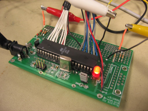
Above: Close-up of the ATMEL Mega32 micro-controller on PCB. The LED acts as a power-up indicator.
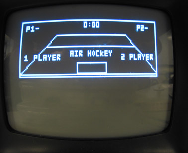
Above: Intro screen: player 1 can choose 1-player mode or 2-player mode by moving the paddle to left or right
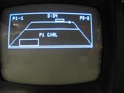
Above: Screen freezes for one second after a goal is scored.
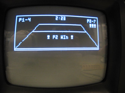
Above: Victory screen: Player 2 wins after taking 3 sets (indicated by the 3 "trophies" on the top right corner).
Video showing how physical paddle movement is translated into movement on screen (format: RealVideo size: 1.99mb)
Click on the link to obtain the program code in proper formatting: dualtv.c
Appendix: Parts and Cost Listing
|
Part |
Unit Cost | Quantity | Total Cost |
| ATMEL Mega32 micro-controller | $8 | 1 | $8 |
| Custom PC board | $5 | 1 | $5 |
| 9V Power supply | $5 | 1 | $5 |
| Solder board | $2.50 | 2 | $5 |
| Rare-earth magnets (provided by Dr Bruce) | - | 6 | - |
| Unipolar Hall-effect digital switches, model A1101 and A1102 (sampled from Allegro) | - | 16 | - |
| Black and white TV (rental) | $5 | 2 | $10 |
|
Total |
$33 | ||
| Task | Member |
| High level concept - choice of input device and video output | Michael, Henry |
| Testing Hall-effect sensors | Michael, Henry |
| State machine & game flow | Michael |
| Ball dynamics calculation | Michael |
| Video generation (interlacing and perspective projection) | Henry |
| Making paddles / sensor array casing | Henry |
| Soldering | Michael, Henry |
| Writing this report | Michael, Henry |
Final stage of testing (playing)
Background Reference
1. Air Hockey, from Wikipedia <http://en.wikipedia.org/wiki/Air_hockey>
2.
Philippe Bekaert, Yves D. Willems. "Viewing
in 3D". March 1999. Computer Graphics
Research Group
Department of Computer Science - K. U. Leuven. <http://www.cs.kuleuven.ac.be/cwis/research/graphics/INFOTEC/viewing-in-3d/viewing-engels.html>
3. Rare Earth Magnets - Safety <http://www.rareearth.org/magnets_safety.htm>
Datasheets
4. Atmel ATmega32 Datasheet <http://instruct1.cit.cornell.edu/courses/ee476/AtmelStuff/full32.pdf>
5. Atmel STK 500 Datasheet <http://instruct1.cit.cornell.edu/courses/ee476/AtmelStuff/stk500.pdf>
6. Codevision C user manual <http://instruct1.cit.cornell.edu/courses/ee476/codevisionC/cvavrman.pdf>
7. Allegro A110x Unipolar Continuous Time Switch Family Datasheet <http://www.allegromicro.com/datafile/1101.pdf>
Vendor Sites
8. Allegro MicroSystems, Inc. <http://www.allegromicro.com/>
9. MPJA Online <http://mpja.com/>
10. Radioshack <http://www.radioshack.com/>
Code and Design References
11. Dr Bruce Land's Video Generation Webpage and Code <http://instruct1.cit.cornell.edu/courses/ee476/video/index.html>
12. Dr Bruce Land's Fixed Point and Mathematical Functions Webpage and Code <http://instruct1.cit.cornell.edu/courses/ee476/Math/index.html>