Cooler-Bot is an autonomous vehicle that uses ultrasonic transducers to sense distance and direction to a remote ultrasonic mobile unit that it is designed to follow.
Our original goal was to design a vehicle that would carry a beverages for the user and follow them at a distance of about 1m around the Atmel MEGA16L microcontroller. This vehicle would be ideal for example on a golf course, allowing you to play golf and have a beverage at hand. We decided to use ultrasound for location detection. For the robot, we used a modified, gutted RC car. The car follows a small, remote ultrasonic mobile unit. When the distance to the mobile unit exceeds about 1m, the car will travel in the direction of the mobile unit until the distance is again less than 1m.
First, we found the resonant frequency of the sensors since there was no datasheet available. We then wrote code to detect and emit short ultrasonic (23.8kHz) pulses. After this, we modified the code to detect distance between an emitter and a receiver. This was then extended to two receivers. We then created a second board that was a simple mobile unit. This board resent any ultrasonic pulses it received, effectively doubling the range. Finally, when all these parts were working, we integrated and tested each system until it worked satisfactorily.
Our project is organized as follows:
MEGA16L
We used the MEGA16L for its A/D capabilities. We chose this over the MEGA32 since we did not need the extra memory. Program details are discussed later.
Rear Motor
This motor was controlled via a MOSFET and powered by the car batteries. This motor is used for forward motion.
Front Motor
This motor is controlled through an H-Bridge and again powered by the batteries. This controls turning of the car.
Ultrasonic transducers
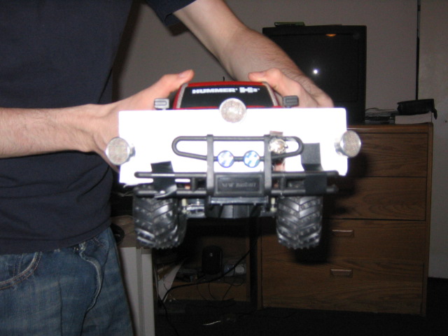
These transducers were found in lab. One transducer on the car is used as a pulse transmitter. The transducer on the mobile unit is used to listen for pulses and then immediately retransmit another pulse. The remaining two transducers on the car are used for receiving this retransmitted pulse, thus allowing us to determine distance and direction.
There are no applicable standards for our project. However, we imagine the noise would annoy several types of animals.
This type of location is common enough and well known enough that it seems unlikely that there are any active patents regarding our project.
The program on the MEGA16L on the car was used to transmit and detect an ultrasonic pulse, and to control the motors when it was proper. Timer1 and Timer2 were set to overflow at 23.8kHz, and thus OC0 and OC2 produced 23.8kHz square waves. OC2 was switched on and off to power the transmitter, and it was pulsed for a short duration several times a second. OC0 was feed back to an input pin for tone detection.
Tone detection was accomplished using the AD converter in differential mode with 10x gain. Each sample was "multiplied" by the feedback OC0. In reality, the sampled value was multiplied by 1 if OC0 was high, and -1 if OC0 was low. The resulting was low pass filtered by averaging the last 8 samples. This reports a high number if the input is 23.8kHz, but very small input otherwise since:

To determine distance, a timer was run concurrently with the A/D converter. To assure accurate timing, A/D math was done outside of the interrupt to allow the timer to trigger as close to its intended time as possible. The timer had two functions, first to control pulse output and also to then count the time until pulse detection. Each time a pulse was detected by the A/D routine or enough time had elapsed, the A/D input was switched to the other speaker. This way both speakers were sampled and enough time was given for the A/D converter to settle before reading it. Originally, we intended to sample the left and right receivers quickly in succession, however this would not work since the A/D converter needs about 125 microseconds to settle when inputs are switched. This corresponds to minimum observable distance of about 4cm, which was too small for this project. Because we alternated inputs, we could observe both distances by speeding up the pulse rate.
The distance was calculated by averaging the two observed distances. This is not an exact result, but provided enough accuracy for our purposes since the two receivers were relatively close. The rear motors were started whenever the distance exceeded a maximum value experimentally determined to be around a meter. The motors were then stopped if the distance was determined to be less than this value. The motor was pulsed at a 50% duty cycle. This was done because the car's motor was far too powerful and would often stop but still have enough momentum to attack the user. This resulted in the user running away causing the car to chase them due to positive feedback. We initially intended to calculate angle, however we decided this was unnecessary. We could simply determine rough direction by comparing the distances of the two receivers; for example, if the distance was shorter for the left receiver, this would mean that the user to the left of the car. This provided sufficient accuracy to steer the vehicle.
Occasionally, one or both receivers would not be able to hear the retransmitted pulse. To mitigate this issue, we only updated distance values when a valid measurement occurred. This is valid since we assume the user does not move particularly fast and is probably close to the last known position. After a long period of receiving from only one receiver, we would assume that the user was 45 degrees in the direction of the working receiver by adjusting the blind receiver distance to be slightly greater than the working receiver distance. This is valid because we tilted our receivers, so if the user is too far to the right or left of the car, one of the receivers will lose signal. This concludes the car code.
The mobile unit used code similar to the car code. However, the A/D converter simply ran until detection, at which point a pulse was transmitted followed by some silence to settle the transceiver. A/D conversion was then restarted. Refer to appendix for code.
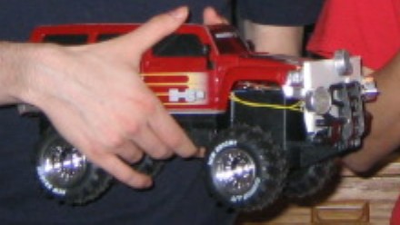
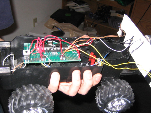
We started from an RC car base. We removed the RF components, leaving simply the body and the motors and wheels. We found that the motors were simple 6V DC motors. We also kept the battery pack as a power source.
The motor setup is shown in the schematic appendix.
The BUZ71 and diode is the same circuit used for Lab 5 (the fan). The H-Bridge chip was used to control the front (turning) motor.
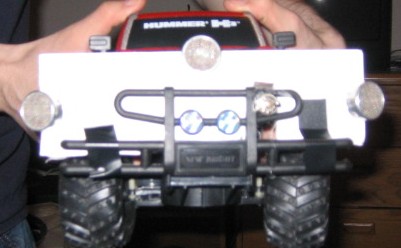
The transceivers operate at 23.8kHz and were somewhat large. The two receivers were placed about 25cm apart. The leads were connected to the A/D converter. PORTA0 and PORTA1 were used for one transceiver and PORTA2 and PORTA3 were used for the other. Using differential mode offered more accuracy (less noise) and built in gain. The transmitter was hooked from the OC2 pin (PORTD7) to ground. When the OC2 pin was active, this created a 23.8kHz square wave pulse. The three transceivers were mounted on a foam core board and placed on the grille of the car.
On the mobile unit, the transceiver was also hooked to PORTA0 and PORTA1. However, it was also connected to OC2 and gated via a BUZ71 to ground. This allowed it to transmit when OC2 was active and the transistor was on, and to receive when both were off.
To power the car MCU board, the 6V array of AA batteries was used. This is lower than the required minimum for the board regulator, however it simply produces a reduced voltage (about 4.75V) and works fine. The motors are not driven off the regulator since it can only source about 100mA. The motors require about 0.8A and run straight off the batteries. We added an external power switch to avoid opening the car to start and stop it.
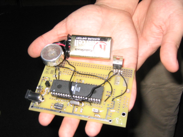
For the mobile unit board, we used a 9V battery. This well within recommended range and is very portable.
Given the correct materials, anyone in this course could easily recreate this project using our code. However, if different transceivers or a different car were used, modifications would be necessary.
We first tried sensing ultrasound using standard microphones. This did not work since these microphones are not designed to work well about 20kHz. Professor Land kindly provided us with actual ultrasound sensors which solved our problem.
Later, we were having trouble with the mobile unit before we found our timing problems. This caused us to rethink our design. We tried a design that used the mobile unit simply to output pulses 1 second apart. The car would ideally hear the first pulse and use this first measurement as the threshold at which to start or stop. Subsequently, the car would use the relative delay from the user. This did not work well at all due to even worse timing issues. We never truly did figure out what went wrong, but going back to our original idea, we managed to correct our problems.
The H-Bridge controlling the front motors had a large output resistance. This caused the motor to be too weak to turn the vehicle. We could not obtain a better chip in time, so we were forced to remove a spring that caused the wheels to tend toward the center. This caused a slight serpentine motion, but improved the car's ability to turn.
Because of the $50 limit, we chose to use the free ultrasonic receivers. While these receivers work very well, they are somewhat directional and worked best within about 2m. As a result, because of the way our receivers are position, the car only follows reliably when the mobile unit is at the same height as the car. More expensive receivers could likely mitigate this issue.
Taking readings several times per second made the car significantly more responsive. However, this also reduces battery life by increasing the duty cycle of the transmitters.
The car follows the transmitter very well. We have never observed the car responding to any stimulus other than the mobile unit. The car does occasionally lose signal at large angles. This causes the car to travel in a circle until it finds signal again.
We observed early on in development that the ultrasonic detection was good to several centimeters. This was better than required for our project, so distance detection is fairly accurate on the car. The car does indeed stop when it gets too close. This high accuracy actually allowed us to determine a rough angle given two separate sensor readings. We set the distance threshold arbitrarily to a number that produced a stop distance of about a meter since exact distance was never a goal of this project. If more precise distance was required, we could easily modify the code to the desired threshold.
In order to ensure the safety of the user and the car, the motor speed had to be limited as discussed earlier. The full speed was far too dangerous (we were often chased away by the car) and the car attempted to destroy itself upon the walls of Phillips several times. The speed is now more manageable (at 50% duty cycle). The slower speed also caused the car to perform much more smoothly with less stopping and starting.
Since other groups were using 23.8kHz receivers, we had to make sure to stay far enough away to avoid interference. We never noticed any interference (other than from our own stupidity).
Our project is usable, however the mobile unit would have to be attached to one's foot. It does accomplish its goal of carrying a drink with the optional beverage holder attachment. Because of the limited ultrasound range and high directionality, the user may have to be slightly patient with the device. With more expensive receivers, we are confident that our car would perform even better. The device requires no technical knowledge to use correctly, however it currently takes some back and thigh muscles while bending over and backing up if you are unwilling to attach the mobile unit to your foot.
We were pleased with the results of our project. We would have liked less directionality and more range from the car, but it does serve its purpose of following the user. Were we have more time and resources, we would use less directional sensors and possibly more power. Other than this, there is not much we would change.
Our project was not constrained by any standards or regulations. Our design was unique and our own. All the code was our own. Some simple setup code (such as timer and ADC start code) was based off previous labs. It is unlikely that this design is patentable since similar devices exist and the technology is fairly prevalent.
| Part | Cost ($) | Obtained From |
| RC Car | 20.00 | Toys R' Us |
| Custom PC Board | 5.00 | Bruce Land |
| Last Year's Board | 2.00 | Bruce Land |
| 2 MEGA16Ls | 10.00 | Bruce Land |
| 4 Ultrasonic Transducers | 0.00 | Found in Lab |
| 2 BUZ71s | 0.00 | Found in Lab |
| 2 TC4424 H-Bridges | 0.00 | Microchip (sampled) |
| Foam Core Board Piece | 0.00 | Salvaged from Dan |
| 9V Battery Clip | 0.50 | Radio Shack |
| Batteries (1 9V, 4 AA) | 6.00 | Estimated Price, found at home |
| Assorted parts (wires, etc.) | 0.00 | From Lab |
| Total | 43.50 |
Both of us worked together on all parts of the project. We switched off often on each task.
Dan Lee