ECE 476 Final Design Project
Snake Arm Ultrasonic Positioning Control System
by Mitchell Kotler and John Penning
Introduction
Our project is a base and glove pair that triangulates the position of the glove in 3D space using ultrasonic pulses in order to use as a control system for the CU Snake Arm.
By having three points on a base, our system calculates position by the distance from each point on the base to the glove. These distances are found by the time it takes for the ultrasonic pulse to get to each point and multiplying by the speed of sound.
Then by sending position coordinates over the serial port, we are theoretically able to, and will eventually, control the arm using 3D reverse kinematics code that the CS subteam is working on. This code allows input in positions to be converted to motor commands that puts the arm into the desired position, with the "head" of the arm at the point corresponding to the glove's position. Our goal was just to track position and allow the program on the computer to calculate how to get to that position.
High Level Design
Rationale
We were talking to the team lead of CU Snake Arm, Tim Roberts, about ideas for the final project. We wanted to make something that would be useful for the team and started coming up with ideas. One idea we thought would be both useful and cool would be some sort of glove which would track position and control the Snake Arm. Tim said that they had the idea of using some sort of glove and had bought some glove at one point, but were not able to get it to work. He also did not know what happened to that glove, so we decided to make our own system for positioning. After talking to Bruce, he suggested using ultrasound in order to triangulate position.
So we set out to build the glove. One of the main reasons we chose this project was its potential for future expansion and improvements due to its association with the Snake Arm team. Plus, we thought it would be an interesting introduction to the world of positioning and ranging algorithms.
Background Math
This project relies heavily on math in order to convert our sensor readings into actual coordinates. From our sensors we collect the time it takes an ultrasonic pulse to get from the glove to each of the three sensors. The times are directly related to the distances by the speed of sound. From these three distances we calculate the coordinates using some trigonometry.
Let the transducer in the lower left corner of the base be point A, the one in the lower right corner B, the one in the upper left corner be C, and the one on the glove be D. We now define the coordinate system as having its origin at A, increasing X in the direction of B, increasing Y in the direction of C, and increasing Z perpendicular to the base toward D.
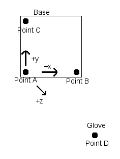
Figure 1: Coordinate System for Triangulation Algorithm
The coordinates are taken in two parts. First we consider the triangle ABD. We know all the side lengths, as the distance from AB is constant, and the distance from AD and BD is gathered from the sensors. We create a right triangle by connecting D to the line AB perpendicularly. Let this point be P. Now we want to find the lengths of segments AP and PD. They are the x and y coordinates of D in the plane defined by ABD. These coordinates will be used to find the 3D coordinates later.
To find these lengths we must solve for the angle A' (let A' be the angle at point A) in this triangle. We use the law of cosine (general form): c2 = a2 + b2 - 2ab cos C. Substituting in our values and solving for the angle, we use it in this form: A' = cos-1(AD2+AB2-BD2 / 2 * AD * AB ).
Now considering triangle APD, we have a right triangle in the same plane as ABD. There are now two cases, A' greater than 90° and A' less than 90°. For A' < 90° we can now solve for PD using the law of sines: sin A' / PD = sin 90 / BD, solving for PD, PD = BD sin A'. By Pythagorean theorem AP = (BD2-PD2)½. Let x1 = AP and y1 = PD. For A' > 90° the angle of the right triangle is the supplement to A', so we can now solve for PD using the law of sines: sin (180-A') / PD = sin 90 / BD, solving for PD, PD = BD sin A'. By Pythagorean theorem AP = (BD2-PD2) ½. In this case x1 is in the negative direction, so let x1 = -AP and y1 = PD.
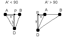
Figure 2: Finding 2D Coordinates in Plane of Triangle Formed by Two Sensors and the Glove
We now do the same exact calculation for the triangle ACD. This will give us our second set of coordinates, x2 and y2. From these coordinates you can find the 3D coordinates. The true x coordinate is equal to x1. This coordinate was just in the direction of B. Similarly, the y coordinate is equal to x2. The z coordinate is found by Pythagorean theorem. Two right triangles are formed, giving us two formulas for z: z = (y22-x12) ½ and z = (y12-x2 2)½. These should be mathematically equal, but since there is bound to be error they will probably be a little off. This is dealt with by finding both values and using the average of them as our z coordinate.
Logical Structure
The base consists of four ultrasonic transducers. One is used for outputting a signal and is hooked up to the output compare pin on the Mega32. The other three are connected to a high pass filter/amplifier, which is fed into a tone detecting circuit. The output of this circuit is hooked up to the three external interrupts on the Mega32, allowing it to record the time when each transducer first detects a pulse. The base also has a serial connector to connect to the computer. This sends the data, after calculating the coordinates, to the computer. This can be viewed in Hyperterminal and in the future will be able to connect to our Snake Arm control program, but for now the data can be analyzed in Matlab.
The glove consists of two transducers. The transmitter is connected to the output compare pin on the Tiny26. The receiver is connected to the same filter/amplifier and pulse detection circuit as on the base receivers. This also feeds to the external interrupt on the Tiny26. The Tiny26 simply waits to detect a pulse and then echoes a pulse back.
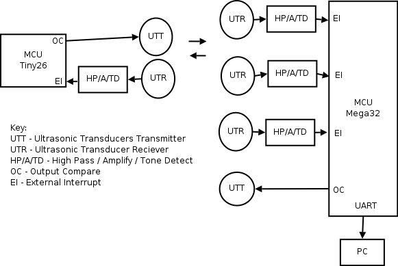
Figure 3: High Level Block Diagram of Overall Design
Hardware/Software Tradeoffs
Our original idea was to detect signals from the transducers using the ADC, and use software to determine whether or not there is a signal. This obviously has many speed issues. We would need to continuously run the ADC, which takes a non-negligible and indeterminate amount of time to complete a conversion, and switch it among three channels. We would than have to determine whether or not there is a signal in software based off these readings. Since the timing of the signal detection is very important, and since most other projects using ultrasonic transducers on the web recommended using tone decoders, we decided to go ahead and use tone decoders to detect the signals in hardware. This made our hardware significantly more complicated than we originally planned, but allowed us to use external interrupts for more accurate timing on when the signal is received. Our hardware switched from just an amplifier circuit for each transducer, to an amplifier circuit, a tone decoder circuit, and a comparator circuit. This hardware was necessary however, as doing it in software was not a viable solution.
Standards
The only standard implemented in our design is the RS232 standard for serial communication. It is used in order to communicate between the microcontroller and the PC. It is followed by using the microcontroller's USART and using a MAX233 chip.
Patents, Copyrights and Trademarks
As this project was an original idea for a student run project team, there are no patent, copyright, or trademark issues involved with the project. Although we did get some ideas for our circuits online, they were all from sources which offered the information for free use.
Program/Hardware Design
Program Details
The programs were not overly difficult. The glove program is extremely simple. It just needs to initialize the needed components, then waits in an empty for-loop. Upon receiving an external interrupt it outputs a pulse. The only tricky part for the code was the difference in the timer. The Tiny26 timer requires different output compare registers for toggling the output and for resetting the value. This caused our output to not be correct. After a few careful re-readings of the data sheet we figured out what the error was and corrected it.
The base code is slightly more complicated, but still not terribly difficult. The algorithm for triangulation is complicated mathematically, but easy to program after working it out. The base's main loop resets the timer, sends out a pulse, and waits for each sensor to detect the echo or times out after a reasonable amount of time (determined by the maximum range of the transducers and how long it takes sound to travel that distance). If all sensors receive a value, the time of arrivals of each one are used to triangulate a position and send it over the serial port to a computer. If it timed out, no calculations are done. There is also a software check done on the sensors to make sure that their time is only recorded at appropriate times, and a sanity check on the value since the glove must be a certain distance back in order to function properly. Serial is implemented using interrupts so as to not block the program. The timer for the timeout is also implemented using an interrupt in order to not force the program to check it constantly.
Hardware Details
Our project consists of two separate parts, the glove and the base (see Appendix B for schematics). The glove uses two Kobitone 40-kHz ultrasonic transducers, one for sending signals (the 255-400ST12) and one for receiving (the 255-400SR12). These are each placed in parallel with a 2 Kohm resistor, which absorbs some of the inherent capacitance in the transducer and creates a smaller time constant (so the signal does not remain in the transducer after being received). The transmitter is connected directly from ground to Port B1 of the glove's ATTiny26 microcontroller, which sends pulses directly out to the transducer where they are converted to ultrasound.
The receiver is connected to the microcontroller through a series of ICs for analog signal conversion. First, the received signal is sent through the transducer (which is also connected from ground in parallel with a 2 Kohm resistor) into a non-inverting high-pass amplifier created from a National LM6172 op amp. This op amp uses a Vcc/2 line at the input stages, which was made by dividing the Vcc rail with two 10 Kohm resistors. This Vcc/2 rail is connected to the non-inverting input with a 3 Kohm resistor in series, and to the inverting input with a 1 Kohm resistor in series. The inverting input then connects to the output with a 100 Kohm resistor, and the input from the transducer is fed into the non-inverting input using a .02 microfarad capacitor. This creates a cutoff frequency and gain as follows:
fo = 1/(2 * 3x103 * .02x10-6) = 8.33 kHz
Gain = 1 + (100x103/1x103) = 101
The output of the amplifier is then fed into an LM567C tone decoder, which pulls a 5V signal low on one pin when it detects a set frequency on another pin. The tone decoder subcircuit was mostly laid out according to the diagram in the LM567C datasheet. The input is fed into the tone decoder through a .02 microfarad capacitor. Hooked up in series between pins 5 and 6 are a 22 Kohm resistor and a 10 Kohm potentiometer. The total resistance of this is used in determining the detected frequency of the tone decoder, as determined in this equation:
fo = 1/(1.1 * R1 * C1)
where R1 = the total resistance of the 22k resistor and the pot, and C1 = the capacitor between pin 6 and ground (in our case, .001 microfarads). As you can see in the schematic, there are 2 other capacitors going from tone decoder pins to ground, and one resistor going from another pin to Vcc, as labeled.
Since the tone decoder outputs an analog DC signal somewhere between 0V and 5V depending on the presence and strength of an input frequency within its bandwidth, we placed an LM311 voltage comparator at the output of the tone decoder. The LM311 compares the tone decoder output with a voltage on the other input, and pulls the output down to a digital "low" signal when the first input is greater than the second. To get the comparison to be done at the correct voltage, we used a 10 Kohm potentiometer at the second input connected between Vcc and ground. This way we could tune the comparator to a desired voltage at which we could detect a usable ultrasonic signal and tune out noise. The output of the comparator is connected to pin B2 of the MCU, and also to an LED and 1 Kohm pullup resistor for debugging purposes (the LED turns on when a signal triggers the MCU external interrupt).
One of the biggest engineering tradeoffs we were forced to make involved the tuning of the potentiometers for the voltage comparators. If these pots were set too low, then a lower-amplitude signal from farther away could then be detected, giving us a longer range but more error due to excess noise received. If the pots were set too high, then the amount of noise drops but then the range becomes incredibly limited. We had to decide upon an optimal potentiometer setting that would minimize noise and maximize range, but unfortunately there was no way to tune them to a perfect setting.
The ATTiny26 is set up on the same breadboard as the rest of the glove circuit. It is set up in the standard fashion for off-STK operation, as seen in the schematic. The glove circuit is powered by a 9V battery connected to a Freescale battery clip/5V regulator, which was sampled from class.
The base uses a design that is similar to the glove, except since there are three receiver units, the receiver subcircuit (transducer to op amp to tone decoder to voltage comparator) is replicated threefold. The same op amp DIP package was used for two of the receiver subcircuits because it was a dual package. Besides that, the receiver subcircuits are all identical, because we wanted the signal to reach the MCU in the same form all three times, and with the same amount of delay from going through each device. These subcircuits go to pins 3, 14 and 15 of the MCU on the base. The transmitter is again directly connected from the MCU (pin 4) to ground, with a 2 Kohm resistor in parallel. The transmitter and 3 receivers are mounted on a piece of foam core, with the centers of the receivers 49 cm apart on the x and y axes, and the transmitter up and to the right of the bottom left receiver. This positioning allowed us to perform relatively simple triangulation.
Our base uses an ATMega32 for its MCU. This allows us to have three separate external interrupts, more memory, and a serial interface to a PC. This serial interface consists of a MAX233 RS-232 serial driver hooked up to the Tx and Rx pins on the MCU, and a standard 9-pin serial connector. The Mega32, MAX233, serial connector, and all accompanying resistors and capacitors were all mounted on Bruce Land's standard ECE 476 protoboards, along with the power connector, power switch, and voltage regulator, while the transmitter and receiver subcircuits were all built on a single breadboard.
Reused Code/Designs
To guide us in designing the op amp circuit, we used this guide from Texas Instruments, which proved helpful in setting up the amp for a single power supply. The schematic after which we modeled our design is the second one on page 14: http:// instruct1.cit.cornell.edu/courses/bionb440/datasheets/ SingleSupply.pdf
We found the site for Kam Leang Robotics when trying to think of different ways to implement our receiver subcircuit, which helped us out quite nicely. This site gave us the idea for the transducer/op amp/tone decoder/ comparator layout, as well as the idea to use potentiometers to tune the tone decoder frequency and comparator voltage: http://www.leang.com/robotics/info/articles/ minison/minison.html
We also used Bruce Land's protoboard as the basis for our base, the design for which can be found here: http://www.nbb.cornell.edu/neurobio/land/PROJECTS/ Protoboard476/index.html
The ECE476 Serial Communications Page helped us out a lot in setting up our serial code.
In the absence of working code from the Snake Arm CS subteam, we used Tim Hawkins' Matlab Kalman filtering code to analyze our data. http://www.techsystemsembedded.com/Kalman.html
What Didn't Work
We were originally using different ultrasonic transducers that worked at 25 KHz and could both transmit and receive signals. However, these were incredibly directional, which limited the area the glove could be and still transmit to all three receivers on the base. We generally were only able to triangulate from one very small area in front of the base, which proved detrimental to the final goals of our project, which were to allow the glove a free range of motion so the snake arm could move in tandem with it. Therefore the glove with the old transducers was basically useless. The new 40KHz transducers were more expensive but less directional, which allowed us to move the glove more freely.
When we still had the old transducers, we used a Maxim MAX4544 analog switch on both the base and the glove to switch from an output signal (on the bottom left transducer on the base) to an input signal and vice versa, so we would only need 3 transducers on the base and 1 on the glove. However, when the analog switch on the base was switched from transmit to receive, the transducer would still be resonating its own sending signal and send back an external interrupt trigger in an incredibly short time to the MCU, which would completely threw off the triangulation calculations. We tried fixing this in software by throwing in delays or shutting off the interrupts except for when they were necessary, and we tried increasing the resistance in parallel with the transducers, but we were still having problems with either the triggering, the reception range, or both. These issues, combined with our problems with the 25KHz transducers, caused us to ditch the analog switches and keep the transmitters and receivers separate.
Results
Speed
Timing is very important to our application. In order to maximize the response times from the input signals, we use the external interrupts instead of polling input pins or the ADC.
The other speed issue we have is with our triangulation code. The code contains some quite complicated math, which we decided to perform in floating point. We do this to for more precision as well as the fact that the built in trig functions are in floating point. Converting between fixed and float is slow, so we figured we might as well take the extra precision benefit if floating point operations are being performed either way. Another option would be to used fixed point instead of floating point. An attempt was made to do this, but did not appear to work correctly and seemed to offer little benefit. We decided to stick with floating point, since it worked adequately, instead of wasting time trying to make fixed point work.
The speed of the code only affects how fast we can get data from the system, as no other processes are running. Another pulse is not sent out until the last one has finished computing. Having a high rate of data input is not highly important however, as the glove should not be moved very quickly. The snake arm itself cannot move extremely quickly, and updating the position of your hand even only a few times a second should be enough to keep up with the speed of the arm. The only other advantage to having more data points would be to allow filtering of the data to be more accurate. The math routine contains some optimizations, but could be optimized further. This may also help accuracy. See the accuracy section for more information on the filtering required on the data.
Accuracy
Accuracy was probably our largest problem with this project. The sensors were much less accurate than we had originally anticipated and were very directional, greatly limiting our range. We had no way of getting around this besides rush ordering better sensors for the last week of our work. These new sensors were 40kHz, which we hoped would be a less noisy frequency than our original frequency of 25kHz, and thier data sheet showed that they were were much less directional. Not much work was required to integrate them into the system. We changed the frequency produced by the chips to 40kHz and adjusted the tone decoders to detect the new frequency by just changing a resistor on each one.
With our new sensors in place we had better range, though still not great. We also seemed to improve accuracy slightly, but the data was still highly imprecise. Holding the glove in one spot would produce jumps in the positioning data around 20cm. In order to make use of this data a member of the Snake Arm CS subteam suggested that we use Kalman filtering. We found a Matlab implementation of a Kalman filter that was easy to use on our data. We altered it slightly in order to have it fit our needs. This turned the data from seemingly random junk to decent data. Although still not extremely accurate, the results are indeed useable after applying the Kalman filter. Note that the Snake Arm interface code has real-time Kalman filtering built in, and therefore can still use the data we give it with our glove, but since the CS subteam hadn't completed it at the time of this project's due date, we simulated the Kalman filtering in Matlab.
Here are some screenshots of analyzed data from our test cases. These show one coordinate versus time, and are being moved in one direction to be able to compare the data to what you know should be happening. the green line is the actual data and the blue line is the data after applying the Kalman filter. Click for a larger view.

|

|
| Figure 4: Movement of X in the negative direction | Figure 5: Movement of Z in the negative direction |
Safety
Our project is quite safe. There are not many dangers associated with ultrasound. It would probably be best to keep yyour dog away from it, however, as their ears may be sensitive to the high pitched sound. The only safety concerns with the glove would be its integration with the snake arm. Although the snake arm has many safety concerns associated with it, as it is a heavy duty mechanical device, those are dealt with by the team and not our 476 project directly. The only other risk our project could introduce to it would be sending it coordinates out of the arms range of motion. If it attempted to move to these points there could obviously be mechanical failues which could lead to parts break and possibly coming off the robot which would be dangerous. However, our data is sent to the arm through the CS subteam's program, which will make sure that data is within the arm's capabilities before being sent to the arm as actual motor commands.
Interference
Interference was also a big problem for our project. At one point, our circuits were detecting signals nonstop in the lab. There were some other groups using ultrasound at the same frequency as us (25kHz at the time), and it appears that much of the equipment in there creates noise that adversely affected our system (monitors, TVs, etc). Richard suggested that we try taking it out to the hallway to test it. After trying it on an outlet that wasn't turned on, we found a good outlet and our debugging LEDs showed that it was working better. We borrowed someone's laptop to see the data coming off of it and it was greatly improved from within the lab although it still needed work. We have been working mostly in the Snake Arm lab (Upson 126) since then, which has no other ultrasound devices running, and much less electrical equipment than what is in the Digital Lab. Interference has been much less of a problem since then.
Usability
The device is not as usable as we had hoped it would be. The transducers on the glove most be kept within a certain range and keeping them pointed at the center of the base as you move it helps it as well. This behavior is not optimal for usability, but is a limitation of the sensors.
As far as actually using the system to control the snake arm, it is less than ideal. It does not offer precise movement, and seems like it would be impractical for trying to control it in any sort of critical operation without major future improvements. It could still be useful for demonstrations as a proof of concept and showing off cool accessories we have made for our snake arm.
We also tried getting the arm integrated into the CS team's program in order to view a 3D model of the arm being controlled by the glove. However, we did not have enough time to collaborate with them in order to get the integration working. It should not be difficult to achieve this integration when we have the time to sit down with the necessary people to help us out.
Conclusions
Expectations
Any project involving wireless communication, as we found out, requires a lot of effort and even more patience. There ended up being a lot of noise that needed to be filtered out, and we ended up not having as free of a range of motion in the glove as we had hoped. Obviously, certain hardware limitations cannot be improved upon when stuck with the same parts. We continually made improvements in hardware and software configurations, but there was only so much we could do with the accuracy and range of the transducers we had. We even tried changing the transducers to the new 40 KHz variety, and while the improvement in range was finite, it still did not come close to getting rid of all the error. However, we deemed this error acceptable because of all the filtering (i.e. Kalman filtering) that is possible on the PC side, at which point the data is being managed by the CS subteam of CU Snake Arm.
We did not expect to have as much hardware tweaking as we did in this project. We expected most of the engineering work in this project to be software adjustments and debugging, but we ended up needing a lot of hardware to get a good signal into the MCU, which meant a lot of analog design, testing, and resistor swapping. Tuning the voltage comparator pots every time they were accidentally knocked out of place was quite a chore.
If we were to do the project again, we probably would find a way to make something that did not involve such incredible precision that ultrasonic positioning requires. When one millisecond's worth of difference in timing equals a 34-cm difference in distance, as it does with the speed of sound, the error we received was bound to occur. The Kalman filtering greatly improved our results, but perhaps triangulation using timing was not an ideal project idea.
But on the bright side, considering all the factors that were basically out to try to make us fail, including a room full of noise (the 476 lab itself) and transducers with limited range, we were still amazed at what we could build with the time and budget we had. With the Kalman filtering on the PC side, our data is definitely usable, and we plan on finalizing this design next semester by putting it onto a PCB, reducing the size of the glove by purchasing surface mount components, and fully incorporating it with the Snake Arm.
Standards Conformance
The only standard that applies to our project is the RS-232 serial communication standard via USART, to which our project fully complies (as mentioned above). The Mega32 chip sends out serial signals according to the standard automatically, as long as the USART interrupt is included in the code, the registers are set correctly, and the baud rate is synchronized. We successfully complied with these requirements, therefore anything placed in the USART buffer was sent across the serial cable to the terminal program on the PC. We used 8 data bits, no flow control, no parity bits, 1 stop bit, and transmitted at 9600 baud.
Standards regarding ultrasound were generally relegated to its medical and materials/structures testing applications, and therefore had no jurisdiction over our project.
Intellectual Property Considerations
While ultrasonic ranging and positioning has certainly been done before, the design and implementation of our glove was our own. We gathered some ideas on how to detect ultrasonic signals from Kam Leang's site, but considering his webpage is intended as a how-to, and since our project is intended for academic purposes only, there are no copyrights being infringed upon. This also applies to TI's how-to page regarding single-supply op amps.
Ethical Considerations
The IEEE Code of Ethics:
1. To accept responsibility in making decisions consistent with the safety, health and welfare of the public, and to disclose promptly factors that might endanger the public or the environment;
We realized that our project may cause harm in the ears of certain animals sensitive to 40 KHz sounds, such as dogs and cats. We advise the users of this project to keep their pets away from the ultrasonic transducers. Also, eventually when this glove actually controls the Snake Arm, we advise that people, especially young children, stay away from such heavy and powerful machinery.
2. To avoid real or perceived conflicts of interest whenever possible, and to disclose them to affected parties when they do exist;
The main ethical consideration involved in this project involved our cross-commitment to this class and to the Snake Arm project team. We knew we wanted our project to be something involving the Snake Arm, but we also knew we could not use the same project for two separate grades. Therefore we designed this glove to have a clear line of demarcation as to where M&AE 490 (Snake Arm) ends and ECE 476 begins: as soon as the coordinates enter the arm guidance program on the PC, it is no longer our 476 project. Also, we did not include this glove project as part of our Snake Arm end-of-semester report and can assert that it has absolutely nothing to do with our grade or credits received in the Snake Arm project course.
3. To be honest and realistic in stating claims or estimates based on available data;
It should be clear from the above report that we are not proclaiming the perfection of our design. We simply believe that given all factors of time and available parts, that our design, while imperfect, is solid.
4. To reject bribery in all its forms;
No profit has been or will be made from this project. No money has exchanged hands except for the sales of the individual parts.
5. To improve the understanding of technology, its appropriate application, and potential consequences;
Being that our project is meant to accessorize an student project team, its purely academic use promotes this goal by definition.
6. To maintain and improve our technical competence and to undertake technological tasks for others only if qualified by training or experience, or after full disclosure of pertinent limitations;
Our training in ECE 476 and over the course of our undergraduate careers was more than adequate to undertake the tasks assigned to us, and we would help other groups only after knowing the technical background and limitations of their project.
7. To seek, accept, and offer honest criticism of technical work, to acknowledge and correct errors, and to credit properly the contributions of others;
The overall ECE 476 "state of the lab" was one of comraderie and respect. We gave and received advice when needed, and gave credit where credit was due (see bottom of report).
8. To treat fairly all persons regardless of such factors as race, religion, gender, disability, age, or national origin;
Our project is useable by all people.
9. To avoid injuring others, their property, reputation, or employment by false or malicious action;
There were no acts of sabotage on our part, and no one else's project was harmed.
10. To assist colleagues and co-workers in their professional development and to support them in following this code of ethics.
We gave our fellow students our full emotional support in the lab, and we certainly hope none of them sabotaged any of the other projects...
Legal Considerations
There are no legal regulations or constrictions regarding ultrasound transmissions if not used in medical, military, or materials/structures testing applications. Therefore, there were no legal considerations in our project.
Appendix
Appendix A: Source Code
- Base Main Source Code
- Base Header File
- Glove Main Source Code
- Glove Header File
- Kalman Filter Matlab Script
Appendix B: Schematics
- Base (click to see full size):

- Glove (click to see full size):

Appendix C: Cost Details
| Item | Cost per Unit | Quantity | Total Cost |
|---|---|---|---|
| White Board | $6 | 2 | $12 |
| Custom PC Board | $5 | 1 | $5 |
| Power Supply | $5 | 1 | $5 |
| 9 Volt Battery | $2.89 | 1 | $2.89 |
| Freescale 9 Volt Battery Voltage Regulator Board | Free (Sample) | 1 | Free |
| Atmel ATmega32 | $8 | 1 | $8 |
| Atmel ATtiny26 | $2.46 | 1 | $2.46 |
| Maxim MAX233CPP + Connector | $8 | 1 | $8 |
| Kobitone Ultrasonic Transducers | $4.79 | 6 | $28.74 |
| National LM6172 | $3.80 | 3 | $11.40 |
| National LM311 | Free (lab) | 1 | Free |
| Various Circuit Components (resistors, capacitors, etc) | Free (lab) | Many | Free |
| Foam board | $2.95 | 1 | $2.95 |
| Total:* | - | - | $86.44 |
*Note: The $50 project budget has been waived by Prof. Land because our project will be put to actual use by the CU Snake Arm team.
Appendix D: Tasks
- Top-level HW/SW design: Both
- Researching parts: Both
- Ordering parts: Tim Roberts (CU Snake Arm team lead, a.k.a. the guy with the Cornell purchasing card)
- Designing the schematics: Both
- Writing the original code: Mitch
- Endlessly debugging the code: Both
- Soldering the protoboards: John
- Assembling the breadboards: Both
- Endlessly debugging the hardware: Both
- Writing the report: Both
- Designing the website: Mitch
Appendix E: References
Data Sheets
- ATmega32
- ATtiny26
- 255-400SR12/255400ST12 - 40khz Ultrasonic Transducers
- LM6172 - Op Amps
- LM567C - Tone Decoder
- LM311 - Comparator
- MAX4544 - Analog Switch
- MAX233 - RS232 Driver
Vendor Sites
Code/designs borrowed from others
- Kam Leang Robotics - Used their Tone Detection circuit
- Texas Instruments - We used a single power supply high pass non inverting amplifier design from this paper.
- Bruce Land's protoboard design
- ECE476 Serial Communications Page - We used this as a base for our serial code.
- Tim Hawkins - We used his Matlab Kalman filtering code to analyze our data.
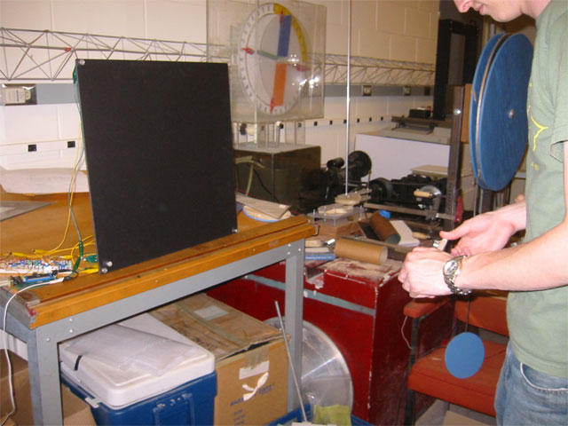
Appendix F: Pictures
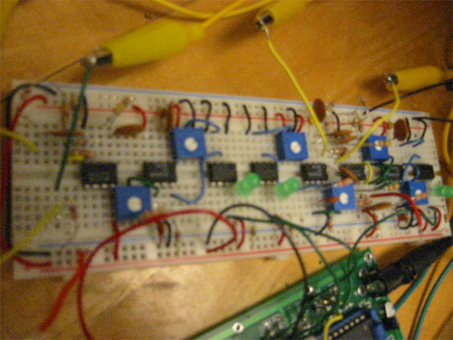
The base circuit
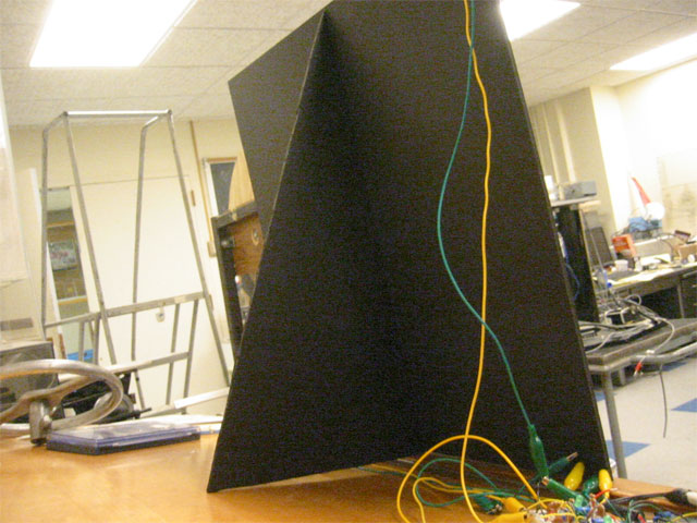
The foam stand
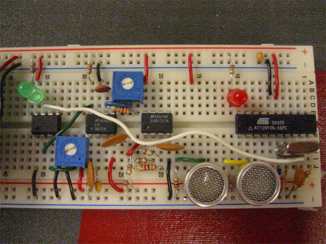
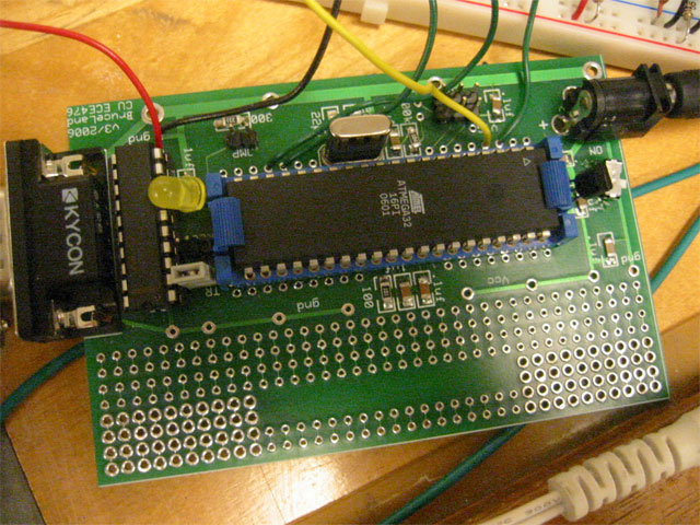
Close up of glove circuit
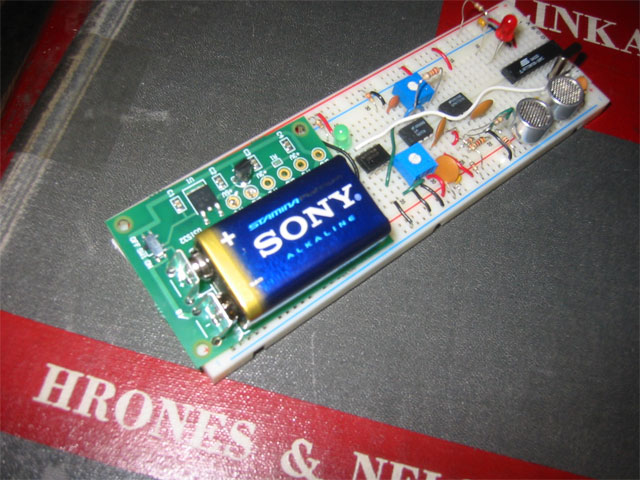
The full glove circuit
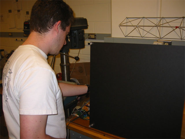
Mitch looking at the base
The protoboard part of the base circuit
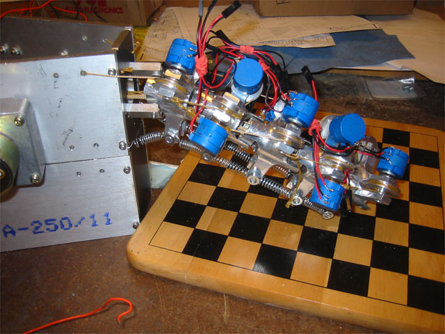
The actual Snake Arm
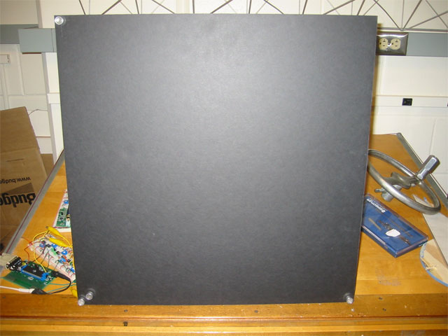
A front view of the base
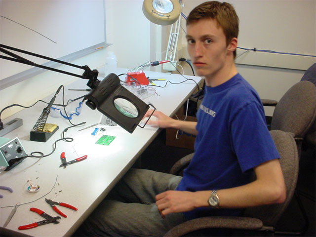
John soldering the protoboard
Appendix G: Acknowledgements
We would like to thank Bruce Land, all the ECE 476 TAs (especially Richard West for making us take a break on one particularly stressful Friday afternoon), Tim Roberts, Justin Wick, Kevin Chiou, TJ Womack, Mountain Dew, and Collegetown Pizza.