By
Tony Huang, th257
Nathaniel Smith, nrs27
| Char | Value | Char | Value | Char | Value | Char | Value |
| 0 | 0 | B | 11 | M | 22 | X | 33 |
| 1 | 1 | C | 12 | N | 23 | Y | 34 |
| 2 | 2 | D | 13 | O | 24 | Z | 35 |
| 3 | 3 | E | 14 | P | 25 | - | 36 |
| 4 | 4 | F | 15 | Q | 26 | . | 37 |
| 5 | 5 | G | 16 | R | 27 | SPACE | 38 |
| 6 | 6 | H | 17 | S | 28 | $ | 39 |
| 7 | 7 | I | 18 | T | 29 | / | 39 |
| 8 | 8 | J | 19 | U | 30 | + | 41 |
| 9 | 9 | K | 20 | V | 31 | % | 42 |
| A | 10 | L | 21 | W | 32 |

| Part Name | Price | Source |
| AtmelMega 32 MCU | $8 | ECE 476 Lab |
| Custom PC Board | $5 | ECE 476 Lab |
| RS232 Connector | $1 | ECE 476 Lab |
| 2x16 LCD Screen | $8 | ECE 476 Lab |
| Wires, Resisors, Tri-Pots | $0 | ECE 476 Lab |
| 5V Power Supply | $5 | ECE 476 Lab |
| LMC7111 CMOS OPAMP | $1.69 | ECE 476 Lab |
| QEC122 IR Emitting Diode | $0.54 | Digikey |
| L14F2 IR Detecting Photodarlington | $1.68 | Digikey |
| RS232 CPP | $0 | Sampled from Maxim |
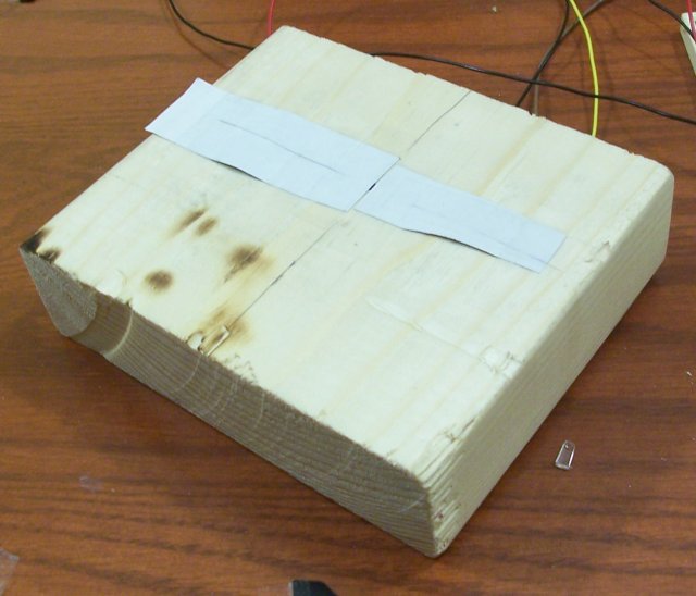
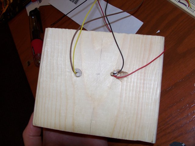
| Wooden Block | $0 | Scrap from Lowes Home Improvement |
| Total | $30.91 |