|
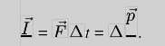
ECE 476: MicrocontrollersOzan Mutluer Erinc TokluogluIntroduction | High Level Design | Program/Hardware Design | Results | Conclusion | Appendices | CodeIntroductionThis ECE 476 Final project is an interactive soccer video game designed and built by Cornell students and soccer enthusiasts Ozan Mutluer and Erinc Tokluoglu. The game focuses on a penalty kick where the user is to enter the direction of the shoot by a keypad and the power and inclination of the shoot through hitting a real soccer ball. The ball is moves on the screen with the relative speed that the user hits the ball. The shoot is either a goal, an out or is saved by the goalkeeper. The goal keeper is designed to mimic an artificially intelligent unit. The game ends when the user succesfully scores 5 goals. High Level DesignRationale and sources of your project idea: The main reason we decided to work on this video game as our final project, was to create a unique, life-like simulation of a physical sport which the game player can experience as closely as could be achieved by a processor-user interface. Our idea was to create a simulation of soccer, more specifically penalty kicking, that was as close to the real thing as possible. The consoles used in regular soccer games are all button based and nothing compares to the actual thrill of hitting the ball yourself and seeing it go into the net. To achieve this user-processor interaction to enable real life soccer playing experience, we decided to look for ways of interfacing a regular soccer ball, as a user input source, with the microcontroller. To achieve this, we decided to work on a novel hardware design, making use of sensors, which would enable the user to input initial ball velocities, through an accelerometer, to the microcontroller, that would be efficient, safe and accurate enough to be suitable for enjoyable game playing. Background Mathematics and Physics: Our soccer game, Soccermania!, employs some of the basic principle of Newtonian physics, namely momentum transfer and projectile motion. These notions are well known to all of us, probably from high school or freshman physics, but a basic review of these notions here, will help make clear the logical structure of the code we used for this simulation. Impulse as you know is defined as the instantaneous change of momentum, given by:
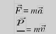
As seen above impulse is given by the applied net force on an object, multiplied by the time of contact with the object, resulting in a change in the momentum vector of that object. Force and momentum are defined as below:
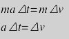
Applying these definitions to our initial impulse equation yields:
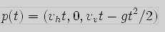
The above equation relates change in velocity to acceleration multiplied by a change in time. We can use this basic physical principle and an accelerometer that can yield results both in x and y axis, to calculate the initial velocities of the ball in the x and y planes and then determine its trajectory, through another basic equation of physics, the all too well known projectile motion equation given below:
Here p(t) represents the position of the ball as a vector in the x,y plane, with px(t)=Vxt determining its horizontal position and the expression py(t)=Vyt – (1/2)gt^2 determining the position of the ball in the y-axis. Hence if we manage to read acceleration values in 2 directions, we can pin point the position of the ball in time. The time we are especially concerned with is the time when the ball reaches the goal, given by: t = X/Vx , where X is the distance to the goal and Vx is the speed parallel to the x-axis. The Logical Structure: The logical structure of the project can be summarized in three main categories. The 1st priority is to come up with a hardware set up, that can accurately detect changes in acceleration and allow accurate, efficient sampling, with safety notions nagging in our heads as we are kicking a real soccer ball in lab. This includes a basic setup for stabilizing the ball without significantly hindering its motion, positioning and orienting a two-axis accelerometer, and sampling 2 different readings from the accelerometer procedurally and simultaneously, trying to achieve a level of efficiency that allows simultaneous readings from both axis, without missing the peak readings of any of them. Our user interfacing also includes a keypad, which has a very simple scanning routine, which upon the pressing of two designated buttons changes the direction vector of the ball. The second priority is to use the data, to calculate or determine direction vectors, scalar speed values, pixel speed values and designated coordinates on the screen where the simulated ball is supposed to go. This has to be done in such a fashion, as will be discussed later, to compensate for slowness and memory considerations of floating point calculations, which require a lot of instruction cycles and memory, so that they can be done within our delicate timing limit of 60 lines per frame, using 16-bit fixed point macros which will be discussed when we refer to the details of our code. The 3rd priority is the game playing, drawing and erasing of figures and updating of images every frame. We have an elegant frame-timing setup that handles initializations, calculations, point settings, and image handling in separate frames, so as to maximize the allowable instruction time to prevent possible artifacts. This scheme is based on a game-playing state machine, with each state having a specific purpose. In fact we are proud to say, that the way our code is organized fully optimizes the microcontroller and is able to handle a good amount of image printing and calculation. The general setup of the user interface, namely the accelerometer and the keypad, interfaced with mcu with its output to video is provided below. Hardware Software Tradeoffs: Due to the positioning of our user ball controller, the accelerometer needs an amplification of at least 4 fold. One basic way of doing this was simply using 2 non-inverting op-amp based amplifiers. This notion, although trivial, would save us a 2 shifting instructions but due to its insignificance it was not carried out. We are not using the ADC in a differential mode that supports input gain, so required signal amplifications were carried out simply in software. Relevant Patents: Upon a little bit of internet surfing, we found a game that utilizes a similar notion of game play. The name of the product is Soccer-Penalty Shoot Out Game, for more information here is the link to a website where the game can be purchased online:
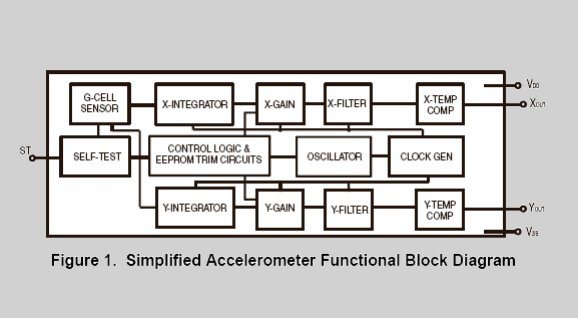
Program/Hardware DesignHardware Details: The hardware interfaced with the microcontroller in the input end consists of a keypad and an accelerometer. The keypad is used to determine vector direction of the ball. The accelerometer we used for velocity inputs was a MMA6261 XY-axis, 1.5g Acceleration Sensor from FreeScale. The simplified block diagram is provided below:
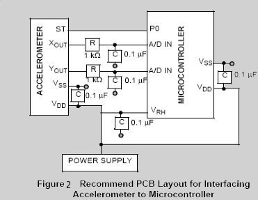
The MMA6200 series accelerometers from FreeScale include 1-pole low pass filter for noise reduction and temperature compensation with an output current range up to 200Îśa, also sustaining capacitive loads. At full swing it can measure accelerations up to 1.5 g in the two axis of the horizontal xy plane. It has a 2.7V to 3.6V low power operation. Here is the block diagram for suggested way of interfacing the accelerometer with a microcontroller:
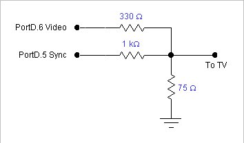
The accelerometer is first soldered to a bread board then connected to the STK 500 board through PORTA, which supports 8-bit Analog to Digital conversion with ATMEL ATMega 32 with 8-bit precision. The ADCSRA is set to 0b11000110.(ADEN= 1, ADSC=1). The conversion is started by writing one to the ADSC, and the ADPS prescalers(110) determine the sampling frequency of the analog input, CLK/4. We were using the ADC in single ended input configuration, with the Xout of the accelerometer tied to ADC2 and the Yout of the accelerometer tied to ADC3. The last four bits of ADCMUX selects between the inputs and our initial difficulty was to toggle these last four bits from 0010 for reading the X-axis acceleration and 0011 for reading the Y-axis acceleration. A single ended ADC conversion takes about 13 clock cycles, which is not so bad timing wise, but the ADCMUX settings have to be made right after the conversion is done so that we are able to read simultaneous results from the accelerometer, just in time, without losing any of the peak acceleration readings. Since the timing of the code was frame based setting the ADCMUX in another frame would take at least 1/60 s, which is approximately the time it takes to fully scan the screen which brings about a clear risk of losing crucial data. To avoid this we decided to read the ADC values procedurally once in every ten frames. This is not a very high sampling time, but reading the inputs procedurally enables us to change the ADCMUX settings in the procedure, and using the ADCMUX setting in two conditionals in the procedure. This way when the procedure is called, it reads the ADC value for Xout first, sets the last four bits of the ADCMUX, goes into the second conditional to read the Yout values, within the same frame, enabling simultaneous data reading with only a few instruction cycle delays inbetween rather then a frame time. That was the notion of how we handled simultaneous x and y acceleration readings. Since we required more than 8bits of data precision reading the data only from ADCH was not enough. The ADC data was taken from ADCL(LSB) and ADCH(MSB) in our reading procedure and with the MSB first left-shifted 8-bits into 16-bit integers then logically ORed with the LSB from the ADCL. A more serious challenge presented by the acceleration readings was caused by how we wanted to orient the accelerometer. Since we wanted to receive readings from in the vertical direction, the accelerometer is oriented so that the y-axis is vertical. A huge problem that emerges is that now you are getting readings due to gravity. There was also a good amount of noise in the x-output as well. As expected the orientation of the accelerometer greatly effects its stable readings, and there are significantly high readings even when the ball is not moving at all. Thus applying a threshold scheme to use data for calculations was not possible. To be able to detect changes in the readings we started storing old sampled values and comparing them to the new ones, taking the difference of these readings gives us the desired acceleration readings. This of course has a huge disadvantage especially for the y-axis, since we no longer have a full swing of 1.5g, our reading maximum was now reduced only to 0.5g and accelerations above that were not detectable. Luckily we positioned the accelerometer somewhere in between the ball and the pivot point, thus intrinsically measuring lower accelerations, which were then scaled to compensate for this fact that they were at a distance from the ball. But as it will be mentioned later, this setup caused significant problems for us. Here is how the ADC value is determined: ADC= Vin*1024/Vref Thus our acceleration calculations should be: Acceleration = (ADC>>10)*1.5g*4 where the 4 comes from the effect of the position of the accelerometer discussed above. At the output end of the mcu we have the video, from PORTD through which the Video digital to analog conversion was handled. The schematic is provided below:
Figure 3. Video connection to PORTD.
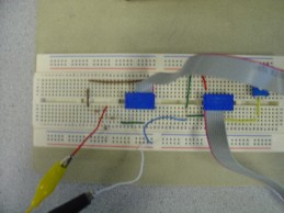
Figure 4. Main Breadboard. Program Details: In the project we borrowed code from the public main, especially for the video DAC, that was provided by Bruce Land. This includes a timer compare on match interrupt service routine that generates the sync pulses, the assembler that loads registers with screen information, the screen array which holds the screen information and character bitmaps for small and large characters. Non-interlaced progressive scan is used where each raster is drawn by pumping 16bytes into the DAC as fast as possible between lines 30 and 230. The while(1) loop is visited every line which is in sleep mode to enter sync ISR without jitters due to timing and when line 231 is reached, we are allowed to calculate and draw on the screen, having only 60 lines of execution time in our hands. In the project we also used the keypad scanning routine and the debouncer, and fixed-point arithmetic macros also provided by Bruce Land. Below are the details of our code. Our code consists one large state machine that includes smaller state machines in itself. The large state-machine has states for the menu items, such as our initial screen, which then waits 100 frames to go into the menu mode. All timing in the code is based on synch ISR, more accurately on the frame time, which is approximately 1/60 s per frame. We did not find it necessary to run another interrupt for timing. All other state transitions of the outer and more trivial state machine are keypad based. The other 2 modes are the game-mode and credits. Integrated into our code are procedures, which call the video line drawing/erasing/inverting procedures also provided by Bruce Land, those procedures are used to draw our models, such as the goal, the goal keeper which by the way is a 2-dimensional figure losing a good amount of pixels, the ball and a direction indication line controlled by 2 designated keys on the keypad for inputting the direction. In addition to those procedures we have the more non-trivial calculation procedures. These include getDistance, which calculates the pixel distance to the goal at a given angle, getTimeToGoal, which given a distance value that is scaled from pixel to estimated meters, returns a time estimation by which the ball should arrive at the goal, given its initial velocity in the x-axis. These procedures widely use the macros to handle otherwise floating point calculations that take far too many instructions and also are memory consuming, thus unsuitable for 8-bit processors especially for video generation where timing is of great concern. Although not a procedure, we have the projectile motion equation implemented in fixed point macros once the x, y-axis velocities and the time to reach the goal is determined. The macros are actually used all around the place, including the conversions from acceleration values to velocity values. Almost everything in the game is procedurally generated including the motion of the goal keeper. To simulate the movement of a real goal keeper, we use a counter that keeps counting then overflowing to set probabilities for the goalie to correctly guess the direction of the ball once it has been kicked. The probability is 70 percent, which makes our goalie, a damn good one. As mentioned before ADC readings are also taken procedurally and there are other procedures like isGoalie to determine whether a shot has been saved. Now that we have described our procedures and the outer state-machine, we can move into the more exciting game-playing mode and start telling you about our code optimizations. Once in the game-mode, you are actually in a smaller but much more elegant state-machine. As you enter the game mode, you get into the state init, where the initial drawings take place. In the game mode, there is an ever-running outer switch statement to draw the direction lines for the possible ball trajectories, which is outside your state-machine. There is a frame-counter, that is incremented in the every time we enter line 231, which as obvious from its name counts the number of frames. Once 30 frames pass, and accelerometer settles down, we start polling it every 10 frames. The initial state, entered zeros the flag with which it is entered, meaning everything there is executed only once except of course when we need an initialization. We can categorizes our frames into 4 main groups, frame calculate, frame counter%2==0, framecounter%2 ==1, and fc, yet another frame counter, less than 65 frames. If the accelerometer readings report a value above a certain threshold we enter frame calculate. The sole purpose of frame calculate is to carry out the impulse and projectile motion equations in fixed point arithmetic, converts calculated real time velocities to pixel speeds (this is done by flooring since our velocity readings hardly ever pass 4 as will be discussed, fix2int(float2fix()) can be used to floor the number to a char that has to be a whole number since it is a pixel speed). During the calculation frame the game is literally halted for one whole frame while velocities, pixel velocities, final position of the ball are determined. Neither the ball or the goalie is allowed to move in the frame, which is done by setting a calc timer to zero and which is incremented in the ISR exactly when lineNumber is reset, which is done once per frame and is not allowed to pass 1. The calculation frame once done sets up a play flag to 1. The play flag logically ended with the calc 1 flag enable the transition to the play mode. In the play mode in every even frame, the ball centers are updated, through the usage of direction vectors. Even frames update variables, and check for cases if the goal is supposed to be ended. Odd frames erase and draw the goalie and the ball based on new updated variables. These seperations of calculations, updating of variables and drawing in different frames, increases our time boundaries for execution and greatly optimizes our code, without making game play looking weird. The direction vectors are increments of scalar multiples of vxp and vyp which are equal to each other for simplification. Note here that vyp is not a result of the acceleration in the y-axis. We modeled the game to be 3 dimensional with the field all the way up to the goal representing the xy plane and the goal itself is parallel to the z plane. The vxp, vyp vectors update the ballcenter coordinates in x and y. One further complication we faced here was that those vectors are determined by the direction line set by keypad input and all of these vectors have unequal magnitudes, meaning for the same velocity vx read from the accelerometer, you will have an intrinsically different velocity for each direction. This problem is solved by using vectors the magnitudes are which are close to each other. Non-of these vectors are normalized, but the important point here is their magnitudes should be close to each other. As I said earlier even frames, handle ball center updates and goalie movements, calling moveGoalie, which goal position but does not actually draw or erase the goalie. From our calculation frame, we have a variable called dy, do not let the y deceive you, this is the final point the ball will reach once it reaches the goal, determined by the acceleration in y-axis which is represented by the z-axis in the video game. Once the ball reaches its final destination or if it has been blocked by the goal keeper and passed line 60 with a negative velocity, the game is stopped and play flag is set to zero and a new flag is raised, which is shotdone. Shotdone takes us to the fc frames, which are frames to waiting for a while, then clearing out the screen. Once fc reaches 65, this condition takes us back into the init state, where fc is set back to zero and initial drawings are carried out. If the score reaches 5 or the user presses 3 on the keypad, we leave the game mode, into credits mode, where we print out our credits and quit the game. Things we tried but did not work The saddest of all the things that we tried but ended up not working was related to the projectile motion equation. Although our macro based calculations seemed to be working we were not able to get velocities that were able to reach the goal. Soon we realized that this was due to the orientation of the accelerometer, and the effect of gravity, which had cut down our reading range from 1.5g to 0.5g, which meant we were unable to distinguish between accelerations above 0.5g. We tried the velocity calculations by hand and using the projectile motion equation realized that the velocities we read from the accelerometer were yielding negative results by the time ball actually reached the goal. In desperation we tried scaling our velocities so that game play would be possible, but our trials showed that in any sort of scaling there was a higher probability for the ball going out too high or too low then ever finding the goal, since our scaling efforts were not physically justified. As a last resort we took the following short cut. Instead of using the vz value for the determination of the final level of the ball once it reaches the goal, we set up boundaries for the ADC acceleration readings we had and set up discrete dy values (final destination) for each acceleration boundary in the z(video) or y(real) axis. This is partially justified, since for low time values the time squared term in the projectile equation disappears giving us a relation y = vy*t=ay*timecontact*t. This is a linear relationship, so we set up higher final coordinates for higher acceleration readings. This is also done in the calculation frame. The code for the actual projectile motion equations is still there, commented out, but we believe that with a better accelerometer that has a higher range, this setup and the code can be used to create our desired model. Another thing we wanted to, but could not was to get a direction from the ball, possibly by utilizing a potentiometer. But we could not come up with a setup that would enable this and therefore abandoned the idea. Although we could not find the patent for it, I personally remember playing a soccer game in an arcade (not a penalty kickout), where the producers relied on buttons for direction and the ball for velocity input, which probably means they, too, found a setup to enable direction readings just from the ball, a bit too difficult to handle.
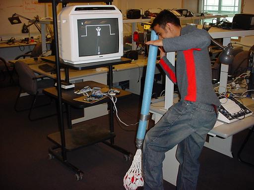
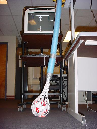
ResultsThe game is functional and properly working. Apart from one or two bugs that occur in very extreme cases, the game is bug-free. We are happy with the game's functionality. Although we were unable to spend more time game enchancements, we believe we have pretty solid conclusions. We have a problem of not printing the score on the screen properly. The digits appear to be scattered around the screen. We believe this problem is due to interlacing. For safety, we have chosen to make the simplest setup possible. We used a basketball net and a pool noodle to guarantee that the ball doesn't fly away when hit. We did not use any RF signals so we didn't have any physical connections to anything involving other people and their projects. ConclusionDesigning and building a interactive soccer penalty game with 2kB of SRAM and 32kb of Flash memory is an extremely difficult project. Throughout our 5 week progress we have been accustomed with finite but close to infinity number of bugs. The most difficult part of the project turned out to be the least expected: video generation. Before starting this project we didn't realize that a moving object on a TV screen is generated by pixel by pixel. Alhthough we have seen video generation in Lab 4, the complexity of that assignment is nothing compared to our final project. However, after some long hours spent in the lab, our efforts payed off and the final project is nearly bug-free other than one or two very extreme cases. The final project is fully functional and working. The accelerometer, the Analog to Digital conversion, the keypad, the AI unit for the goalkeeper and video generation are all functional and working. What might you do differently next time? The only thing we are not fully satisfied with our project is the enchancement of the game. We have spent all our time to prepare a functional game that we were unable to enchance the game mode. In other words, the cake is delicious but the icing is a little plain. Initially, we wanted to add specialties such as more graphics, different goalkeeper modes, different skill levels and a 2-player mode. However, as were limted by time and budget we were unable to reach these goals. Intellectual property considerations: Other than the basis code given to us in Lab 4 for video generation, every analog circuits and digital code are designed, built and written by Ozan Mutluer and Erinc Tokluoglu. IEEE Code of Ethics:
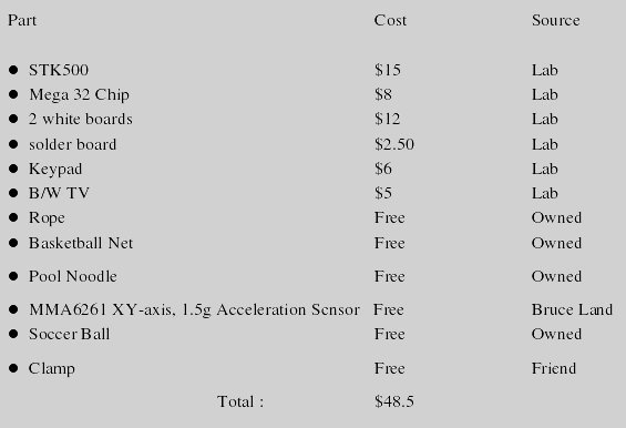
Our project was designed and built by accordance of the IEEE code of ethics: We, the members of the IEEE, in recognition of the importance of our technologies in affecting the quality of life throughout the world, and in accepting a personal obligation to our profession, its members and the communities we serve, do hereby commit ourselves to the highest ethical and professional conduct and agree: 1. To accept responsibility in making decisions consistent with the safety, health and welfare of the public, and to disclose promptly factors that might endanger the public or the environment; We have been very careful in connecting and using the analog ciruits. We have been very kind to other groups while sharing the lab equipment and testing our project. 2. To avoid real or perceived conflicts of interest whenever possible, and to disclose them to affected parties when they do exist; We have been collaborative with our TA's and professor thorughout our project. 3. To be honest and realistic in stating claims or estimates based on available data; We have specified our limits and goals clearly throughout the project. We have also been honest about reached goals and unreached goals in this report. 4. To reject bribery in all its forms; We were not offered any bribes for our work. 5. To improve the understanding of technology, its appropriate application, and potential consequences; We chose this project because we were confident that it would show us difficult problems in solving and integration. We gave our best effort in finding solutions to Analog to Digital conversions and vector calculations. We have been succesful in implementing a difficult idea and project. 6. To maintain and improve our technical competence and to undertake technological tasks for others only if qualified by training or experience, or after full disclosure of pertinent limitations; We never tried any hazardous and potentially dangerous tasks that would not be satisfied by our technical knowledge in this project. 7. To seek, accept, and offer honest criticism of technical work, to acknowledge and correct errors, and to credit properly the contributions of others; We have been collaborative with our TA's and professor thorughout our project. 8. To treat fairly all persons regardless of such factors as race, religion, gender, disability, age, or national origin; 9. To avoid injuring others, their property, reputation, or employment by false or malicious action; 10. To assist colleagues and co-workers in their professional development and to support them in following this code of ethics. AppendicesCost:
Specific Tasks: We have built the circuits and written the code together in the lab from beginning to the end. The lab report and the web page were also written together. Documentation: MMA6260Q Accelerometer datasheet Pictures and Movies:
CodeThe code is available for reference as one file: |