ECE 476 Spring 2006 Final Project
Capacitive sensor based keyboard with MIDI
Siddharth Gauba (sg334) and Byron Singh (bs262)
- Introduction
- High level design
- Hardware Design Description
- Software Design Description
- Results
- Conclusions
- Acknowledgements
- References
- Appendix A - Code
- Appendix B - Schematics
- Appendix C - Costs
- Appendix D - Tasks
The objective of this project was to build a keyboard based on capacitive sensors and then use the MCU to create MIDI encodings for all notes played. The output from the sensors is detected by the MCU using its ADC capability. The sound is played directly by the MCU via a piezo speaker using Pulse-width modulation (PWM). The MCU communicates via serial protocol with an executable interface that has the capability to record MIDI format songs, play them using an integrated Windows Media Player control, and modify them using a hex editor interface.
The design consists of an MCU, a front end Visual Basic interface, an LCD display, capacitive sensing based keyboard, a piezo speaker, and an LED display panel. A block diagram schematic is displayed below. This idea grew out of an idea to make a full-scale computer keyboard using capacitive sensors. It was deemed that it would be nice to have a way of recording one's own music compositions and playing in a convenient, portable MIDI file.
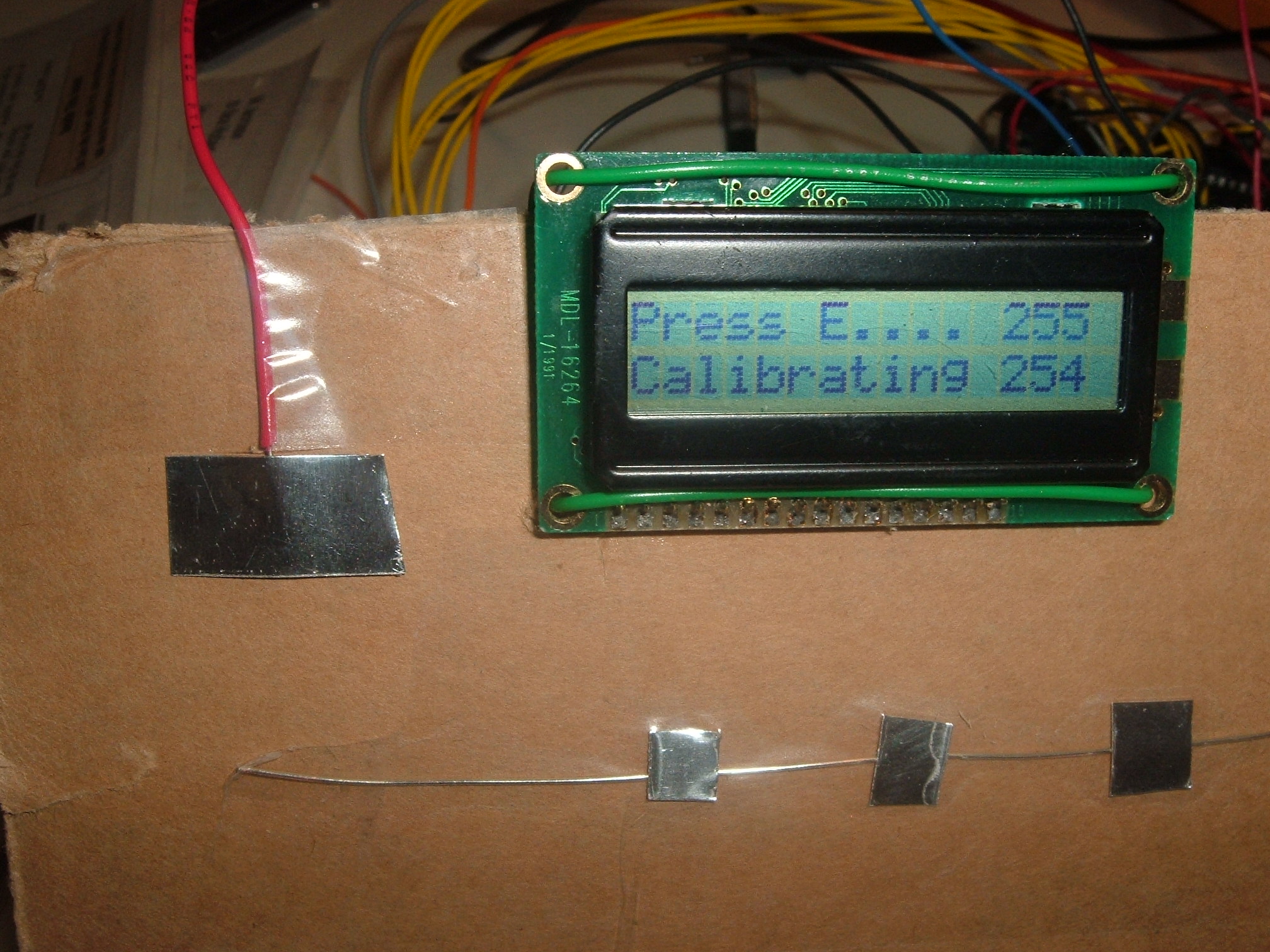
The project is a musical instrument with capacitive sensor input. When a person’s finger is brought close to the electrode attached to the capacitive sensor, a voltage is produced by the capacitive sensor to indicate a button press. The input interface of this musical instrument is electrodes with different area sizes. These different areas produce different capacitive sensor reading and can be detected by the ADC in MEGA32 to decide on the keys pressed. The keyboard consists of 8 keys corresponding to 8 notes on 1 octave. There is an additional button on the top left side of the keyboard which allows user to switch to a different octave.
The notes played will then be converted into midi format and sent to the PC through serial communication. At the PC, a visual basic program is used to receive midi data and save these data in a midi file. The midi file can be played using any software capable of playing the standard midi format file.
As an add-on to the instrument, there is an LCD screen which shows the current and previous notes pressed. It also displays useful information about calibration status, ADC reading, etc. To make our project more interesting, there is a visualization add-on built from LEDs. When a note is pressed, corresponding LEDs light up and decay slowly.
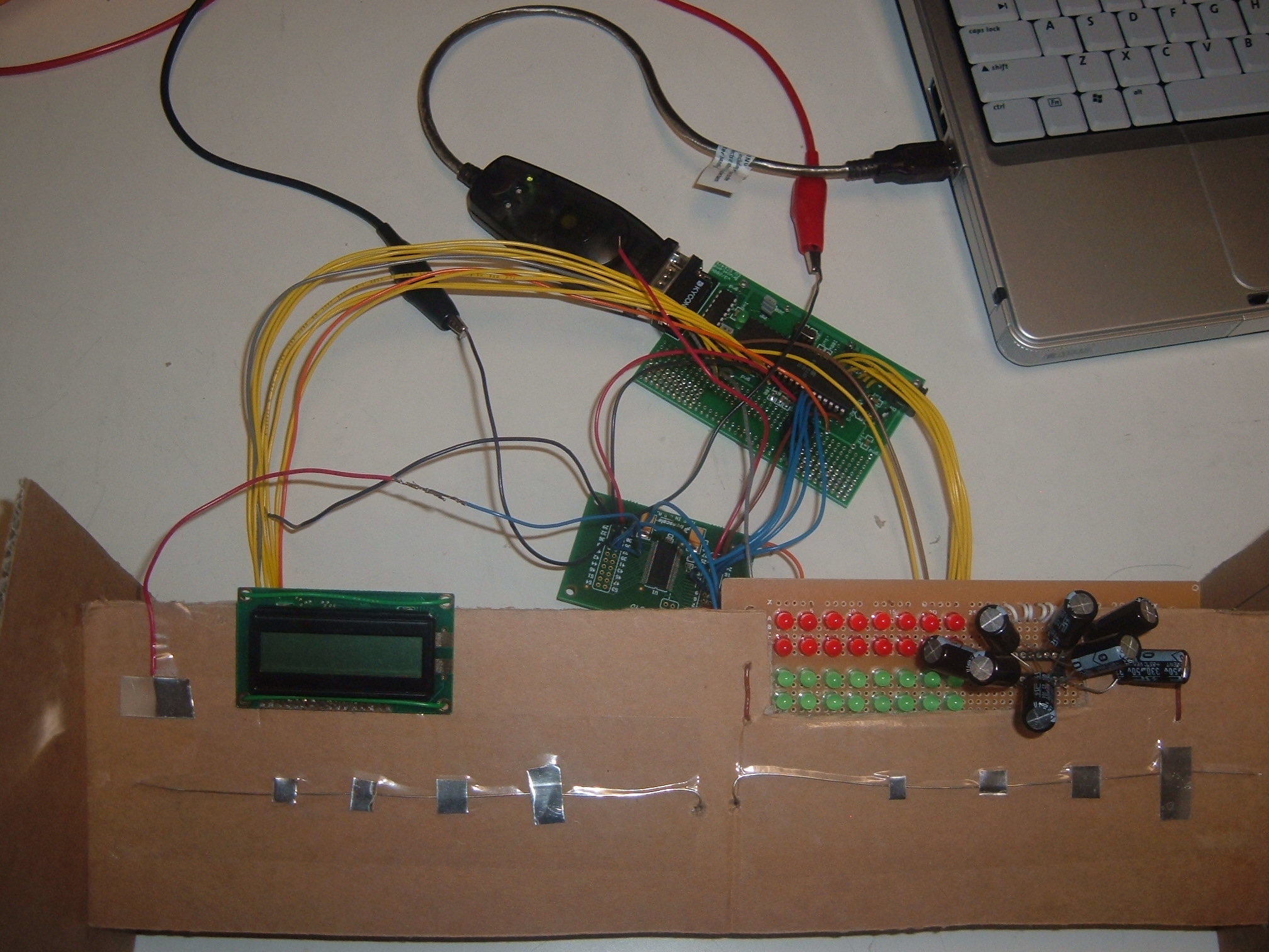
Setup
The photo below shows how the entire system fits together.
Keyboard layout
Several keyboard layouts were tested to determine the optimal layout with respect to ease of playing and clean note detection ability. The figures below show some of the layouts tested:
The last design shown gave the best performance of all the layouts considered. This can be attributed to the fact that the discreteness avoids any ambiguities and sets clear thresholds for each note.
Capacitive sensors
The capacitive sensor chip used is MC33794 . These were donated to the lab by Freescale, and thus their availability and (zero) cost gave them a definite edge over other similar products on the market, most of which had very long lead times and high minimum order quantities. These sensors have 9 channels and give an analog voltage output between the range of 0-2 V, indicating the voltage potential with respect to ground of the sensor connected to the sensing chip. In this project, as per discussion with Prof. Land and tests on several potential materials, a thin aluminum sheet was chosen due to its high sensing ability and malleability.
Speaker
The speaker used to generate sounds is the piezo speaker used in the Lab 1 (stop clock). This speaker is used to generate all the desired frequency sounds by the MCU directly using PWM as described in the software design section.
LED display
The LED display is comprised of 8 strings of 4 LEDs each, of which each string has 2 red and 2 green LEDs. A capacitor is placed across the red LEDs to cause a lighting delay, giving a smooth rise effect whenever the string is activated. The red LEDs and green LEDs are placed parallel as shown below such that the entire string can be driven directly by the MCU port pins (+5V). Below is the circuit diagram for one of such LED strings:
The LED display is also activated in idle mode where the MCU sweeps through all the strings creating a sort of "screensaver" effect.
Capacitive sensing algorithm using ADC
The E-field sensing chip, MC33794 has an internal mux to select one of its 9 input channels. The controls for this mux are, in this case, driven by MCU port pins to control which channel is read. The analog output from the chip is converted to an 8-bit digital value by the ADC on the Mega 32. This value is then used by the calibration algorithm to detect the touching of one of the keys.
Figure: The MC33794Calibration Strategy
Efficient and reliable calibration was one of the main challenges of this project. Several keypad designs were tested for reliability, and the designs were scales up and down to look for any changes in performance. However, it was found that a persistent problem was the variation in the sensor reading from user to user and also for the same user over a period of time. In order to mitigate this issue, a startup calibration scheme was designed. This scheme sends the used messages via the LCD display to press all the keys sequentially so that the system is calibrated properly for each sitting. As a result, the variation in readings is mostly dealt with, including the hitherto encountered problems with different users applying different pressures to the keys.
Sound generationIn order to generate sound, pulse width modulation was used to generate notes of different frequencies. Timer1 compare interrupt was used here to calculate time accurately for the purpose of generating square pulses with desired frequency. Referring to the skeleton codes from previous projects, we set prescaler = 256 so that each cycle is 16us. We can then easily modify the period of interrupt by varying OCR0. The values for OCR0 for different notes are given below:
flash char notes[] = {0,240,212,188,180,160,142,126,120,106,94,90,80,71,63,60};
OCR0 value Note Actual Frequency 0 none none 240 C(0) 130.81 212 D(0) 146.83 188 E(0) 164.81 180 F(0) 174.61 160 G(0) 196.00 142 A(0) 220.00 126 B(0) 246.94 120 C(1) 261.63 106 D(1) 293.66 94 E(1) 329.63 90 F(1) 349.23 80 G(1) 392.00 71 A(1) 440.00 63 B(1) 493.88 60 C(2) 523.25 Formula for calculating the OCR0 values are given below:
Each tick = 16us.
Period = 16us * OCR0 * 2
Frequency = 1/Period = 1/16us/OCR0/2The output of the waveform is through PORTB.3. The output of PORTB.3 will be toggled each time timer0 compare interrupt is reached. To play a note, we can simply set OCR0 to the appropriate value according to the notes[] table.
LCD displayThe LCD display is used for communicating with the user during the startup calibration process and to display important information about any keys pressed. The LCD displays the last four notes played and the frequency of the last note played during regular operation, and displays the key to be pressed by the user during calibration.
MIDI codingAs the user presses a note, the MCU detects it and determines the corresponding hexadecimal MIDI code. This information is then sent via the serial port to the computer to enable recording. In order to allow this, the MIDI code was researched to determine the values associated with a MIDI sound such as the start byte, note byte, stop byte.
Serial Communication Protocol
The MCU sends information via the RS-232 serial port. Information is sent using a UDRE interrupt that sends information as soon as a byte is ready to be sent.
Visual Basic Interface
The Visual Basic front-end was designed in order to provide a convenient interface for a MIDI device such as the keyboard designed in this project. When recording is enabled, the program records all data sent to it by the MCU using the serial interface and keeps a running count of the recording size. After the user opts to stop recording, the program prompts the user for a filename and then appropriately stores the recording. In order to successfully create a MIDI file, it prepends a header file with the proper file-length count as required by MIDI specifications. The header file characters are hard-coded into the program and the characters pertaining to filesize are added to it during the save procedure. The play button plays the file using a control that activates Windows media player. Using the Open file button, MIDI files are displayed in hexadecimal format and can be edited by the user. This was a major challenge as the file had to be opened and closed in binary format and the chars typecasted properly such that extraneous style characters are eliminated while storing the file and converted appropriately to be compatible with the Visual Basic textbox display format. The screenshot below shows the program in operation.
This project has a user-enforced speed of operation, starting with calibration to playing music. The timer interrupts are used to keep track of duration between notes as per MIDI specifications.
The sound generated by the piezo does not sound too much like a piano, although the sound is of the correct frequency. This is because the PWM is essentialy a square-wave generator. In order to smooth the sound, an opamp based integrator was tested. However, this turned out to be ineffective due to the RC constants obtained and the internal capacitance of the speaker and was thus not implemented in the final design. However, by setting the timbre of the MIDI file properly in the header file, a nice piano-like sound was successfully obtained. There continues to be some variance in the E-field sensor readings, but that is inevitable in such a design and we are pleased to have been able to reduce the problem so an extent that it does not hinder normal operation.
There are few safety issues with this implementation. Care was taken such that there is no shorting/bad connection and that the user does not touch any metal parts directly.
This project's development or usage does not cause any sort of interference to other projects. The sound generated is possibly the only signal created by the project.
The design is highly usable by one and all, especially due to the calibration technique that ensures customized operation for each user. The keyboard can be operated in two modes: one where the tune is played directly at the hardware level and the other where it is connected to the computer to make a recording. The executable can be used on any computer that has the proper control files (provided in the zipped folder).
This was an intellectualy satisfying project for both of us. Although not very great musicians, we definitely enjoyed playing around with our design. One of the earliest challenges was understanding how the MIDI specifications worked. The most persistent challenge was definitely the calibration of the keys, which was solved to a large degree by implementation of the startup calibration scheme. Another big challenge was the data handling on the PC application side, in order to be able to save MIDI files, open and modify them in a hex display. This posed a challenge as neither of us were experienced with file handling and data manipulation in VB. We were happy to be able to get add-ons such as the LED display. In sum, we feel that this sort of end-to-end design project gave a good insight of taking a product from the concept stage to the final prototype. Although we do not see much that we would have liked to do differently in this project, it may have been valuable to explore more about the applications of E-field sensors and then evaluate all of them for possible implementation.
Intellectual Property Considerations
This project is different from all the realted ones that we came across, which makes us reasonably confident that there are no Intellectual Property concerns with the project. Past projects regarding MIDI were researched to gain an insight as to their focus and implementation.
IEEE Code of Ethics
We strove to comply in all ways possible with the following ten IEEE ethical guidelines :
1. To accept responsibility in making decisions consistent with the safety, health and welfare of the public, and to disclose promptly factors that might endanger the public or the environment.
This design does not seem to pose any harm to public health and safety. Care was taken when building the circuit to eliminate the possibility of a bad connection and/or short circuits. Most of the components are low-power and thus do not pose major safety hazards.
2. To avoid real or perceived conflicts of interest whenever possible, and to disclose them to affected parties when they do exist;
The interest in this endeavor was to create a good MIDI system. As work was done independently of other groups, there was no conflict of interest.
3. To be honest and realistic in stating claims or estimates based on available data;We have documented in full the abilities and shortcoming of the project in this report.
4. To reject bribery in all its forms;At no point during the project was the idea of the receipt or giving of a bribe entertained.
5. To improve the understanding of technology, its appropriate application, and potential consequences;Whatever understanding and knowledge gain resulted from the design of this project, will be readily shared with future projects that can make use of such know-how.
6. To maintain and improve our technical competence and to undertake technological tasks for others only if qualified by training or experience, or after full disclosure of pertinent limitations.
This project served as a tremendous learning experience. However, at no time were boundaries of safety overstepped. When doing a new task, guidance and supervision was provided by course staff to ensure safety.
7. To seek, accept, and offer honest criticism of technical work, to acknowledge and correct errors, and to credit properly the contributions of others;
All attempts were made to help other groups whenever possible, and inputs made by members of other groups were acknowledged and analyzed to improve upon the design.
8. To treat fairly all persons regardless of such factors as race, religion, gender, disability, age, or national origin;
No persons were treated unfairly during the course of this project.
9. To avoid injuring others, their property, reputation, or employment by false or malicious action;At no point was the development of this project driven by motive of malice or injury of any sort.
10. To assist colleagues and co-workers in their professional development and to support them in following this code of ethics.It is hoped that allowing public web access to this report will be helpful to future 476 students interested in pursuing related projects.
We would like to thank the entire ECE 476 staff: Prof. Land, all the TAs and consultants. Prof. Land was extremely helpful in helping us mould our project goal and idea, especially in the initial stages. Our TA Kenny made sure we stayed on the right track and shared his insights about the best way to go strategically in ensuring timely completion.Ben Madoff helped expand the scope of the project due to his ideas with MIDI integration. The timely and successful completion of this project would have been nearly impossible without the initiative of all course staff to try keep the lab open as much as possible.
Freescale semiconductor Corporation is to be acknowledged for their generous donation of E-field sensors (the MC33794) that constituted perhaps the most critical piece of hardware in this project.
A webpage with frequencies of musical notes
http://www.phy.mtu.edu/~suits/notefreqs.htmlDocumentations for standard MIDI format files
http://www.omega-art.com/midi/mfiles.html
Actual MIDI specs
http://www.borg.com/~jglatt/tech/midispec.htm
Information and tutorial on MIDI files
http://www.ccarh.org/
#pragma regalloc-
#pragma optsize-
#include <Mega32.h>
#include <stdio.h>
#include <stdlib.h>
#include <math.h>
#include <delay.h>
#define lineTime 1018 // a general counter
#define treshold 50
#define zero 0x00
#define one 0xff
#define muxdelay 15 // time to switch channel in capacitive sensor#define th1 20 // treshold for the keys
#define th2 60
#define th3 100
#define th4 140
#define range 20
#define begin {
#define end }#pragma regalloc+
int LineCount;
char Ain0; //raw A to D number
char Ain1;
char lastAin0[5]; //array to store previous 5 ADC values
char lastAin1[5];
int lcdnotes[4]; //array to store previous 4 notes pressed
char lcd_buffer[5]; //string used for lcd displayunsigned char t_index; //current string index
unsigned char t_ready; //flag for transmit done
unsigned char t_char; //current character//variables for midi encoding
int ntt; //note time
int nt; //note
int nton; //note on/off status
int lastnt; //previous note
int lastnton; //previous note on/off status
int index; //general index
int preindex;
int muxcounter; //counter for switching channel
int time; //time
int c1pressed; //channel 1 pressed
int c2pressed; //channel 2 pressed//variables for calibration
int calibration;//boolean for calibration mode
int caltime; //counter for calibration
int caltemp; //temperory value for calibration
int calnote[8]; //array for tresholds after calibrationint i; //used for loops
int octave; //1 = high octave, 0 = low octave#asm
.equ __lcd_port=0x15
#endasm
#include <lcd.h> // LCD driver routines//Musical note values
//C below middle C to C above middle C
//zeros are rests
flash char notes[] = {0,240,212,188,180,160,142,126,120,106,94,90,80,71,63,60};
char note, musicT;
char channel;
//**********************************************************
// -- nonblocking print: initializes ISR-driven
// transmit. This routine merely sets up the ISR, then
//send one character, The ISR does all the work.
void puts_int(void)
begin
t_ready=0;
t_index=0;
UCSRB.5=1;
end/**********************************************************/
//UART xmit-empty ISR
interrupt [USART_DRE] void uart_send(void)
begin
UDR = t_char ; //send the char
UCSRB.5=0; //kill isr
t_ready=1; //transmit done
end//==================================
//This is the sync generator and raster generator. It MUST be entered from
//sleep mode to get accurate timing of the sync pulses
interrupt [TIM1_COMPA] void t1_cmpA(void)
begin
//update the curent scanline number
LineCount ++ ;//start new frame after line 262
if (LineCount==263)
{
time++;
caltime++;
LineCount = 1;
}
end//=================================
//a fucntion to encode time value to be stored in midi format
void WriteVarLen (long value)
{
long buffer;
buffer = value & 0x7f;
while ((value >>= 7) > 0)
{
buffer <<= 8;
buffer |= 0x80;
buffer += (value & 0x7f);
}
while (1)
{
char output;
output = buffer&0xff;
if(output == 0)
output = zero;
while(t_ready == 0)
{;}
t_char = output;
puts_int();
if (buffer & 0x80)
buffer >>= 8;
else
break;
}
}//==================================
//function for lighting LED
void light(int note)
{
if(note == 1)
PORTB.0 = 1;
else
PORTB.0 = 0;if(note == 2)
PORTB.1 = 1;
else
PORTB.1 = 0;if(note == 3)
PORTB.2 = 1;
else
PORTB.2 = 0;if(note == 4)
PORTB.4 = 1;
else
PORTB.4 = 0;if(note == 5)
PORTB.5 = 1;
else
PORTB.5 = 0;if(note == 6)
PORTB.6 = 1;
else
PORTB.6 = 0;if(note == 7)
PORTB.7 = 1;
else
PORTB.7 = 0;
}
//=========================
//function to send the appropriate encoded characters
//after each note press
void shownote()
{
char t,ton;
if(nt == 0)
t = 0x3c;
else if (nt == 1)
t = 0x3c;
else if (nt == 2)
t = 0x3e;
else if (nt == 3)
t = 0x40;
else if (nt == 4)
t = 0x41;
else if (nt == 5)
t = 0x43;
else if (nt == 6)
t = 0x45;
else if (nt == 7)
t = 0x47;
else if (nt == 8)
t = 0x48;
if(octave == 0)
{
t -= 0x0c;
}
if(nton == 0)
ton = zero;
else
ton = 0x40;
WriteVarLen(ntt);
while(t_ready == 0){;} t_char = 0x90; puts_int();
while(t_ready == 0){;} t_char = t; puts_int();
while(t_ready == 0){;} t_char = ton; puts_int();}
//==================================
// print note on LCD
void printlcd(int i)
{
if(i == 1)
lcd_putsf("C");
if(i == 2)
lcd_putsf("D");
if(i == 3)
lcd_putsf("E");
if(i == 4)
lcd_putsf("F");
if(i == 5)
lcd_putsf("G");
if(i == 6)
lcd_putsf("A");
if(i == 7)
lcd_putsf("B");
if(i == 8)
lcd_putsf("C");
if(i == 0)
lcd_putsf("X");
}
//==================================
// set up the ports and timers
void main(void)
{
DDRA=0xf8;
DDRD=0x0f;
DDRB=0xff;
PORTC = channel;
//enable ADC
ADMUX = 0b11100000;
ADCSR = 0b11000111;
UCSRB = 0x18;
UBRRL = 103;
//init timer 1 to generate sync
OCR1A = lineTime; //One NTSC line
TCCR1B = 9; //full speed; clear-on-match
TCCR1A = 0x00; //turn off pwm and oc lines
TIMSK = 0x10; //enable interrupt T1 cmp
//initialize synch constants
LineCount = 1;
lcd_init(16); //initialize the display
lcd_clear(); //clear the display
//init musical scale
note = 0;
musicT = 0;
//use OC0 (pin B.3) for music
DDRB.3 = 1 ;
t_ready=1;
t_char = 250;
time = 0;
index = 1;
preindex = 0;
calibration = 1;
lastnt = 0;
lastnton = 0;
muxcounter = 0;channel = 0x01;
lastAin0[0] = 0;
lastAin0[1] = 0;
lastAin0[2] = 0;
lastAin0[3] = 0;
lastAin0[4] = 0;
lastAin1[0] = 0;
lastAin1[1] = 0;
lastAin1[2] = 0;
lastAin1[3] = 0;
lastAin1[4] = 0;
Ain0 = 255;
Ain1 = 255;
#asm ("sei");
lcd_putsf("line 3"); //string from flash//calibration for the 8 keys
for(i=0; i<8;i++)
{
lcd_clear();
lcd_gotoxy(0,1);
lcd_putsf("Calibrating");
caltime = 0;
while(caltime < 50)
{
lcd_gotoxy(0,0);
lcd_putsf("Ready");
}
lcd_gotoxy(0,0);
if(i == 0)
{
channel = 0x01;
lcd_putsf("Press C");
}
if(i == 1)
lcd_putsf("Press D");
if(i == 2)
lcd_putsf("Press E");
if(i == 3)
lcd_putsf("Press F");
if(i == 4)
{
channel = 0x02;
lcd_putsf("Press G");
}
if(i == 5)
lcd_putsf("Press A");
if(i == 6)
lcd_putsf("Press B");
if(i == 7)
lcd_putsf("Press C");
PORTA.3 = 0;
PORTA.4 = 0;
PORTA.5 = 0;
PORTA.6 = channel & 0x02;
PORTA.7 = channel & 0x01;
caltime = 0;
caltemp = 120-(i%4)*30;
while(caltime < 200)
{
if (LineCount==231)
{
Ain0 = ADCH;
if(Ain0 < 10)
sprintf(lcd_buffer,"00%d",Ain0);
else if(Ain0 < 100)
sprintf(lcd_buffer,"0%d",Ain0);
else
sprintf(lcd_buffer,"%d",Ain0);
lcd_gotoxy(12,0);
lcd_puts(lcd_buffer);
caltemp = (caltemp + Ain0)/2; //gets average value
if(caltemp < 10)
sprintf(lcd_buffer,"00%d",caltemp);
else if(caltemp < 100)
sprintf(lcd_buffer,"0%d",caltemp);
else
sprintf(lcd_buffer,"%d",caltemp);
lcd_gotoxy(12,1);
lcd_puts(lcd_buffer);
ADCSR.6=1;
}
if(caltime < 40)
{
//do nothing
}
else if(caltime < 80)
{
lcd_gotoxy(7,0);
lcd_putsf(".");
}
else if(caltime < 120)
{
lcd_gotoxy(8,0);
lcd_putsf(".");
}
else if(caltime < 160)
{
lcd_gotoxy(9,0);
lcd_putsf(".");
}
else if(caltime < 200)
{
lcd_gotoxy(10,0);
lcd_putsf(".");
}
}
calnote[i] = caltemp;
}
lcd_clear();
lcd_gotoxy(0,0);
lcd_putsf("Notes:");//the main loop
while(1)
{
if (LineCount==231)
{
//Play a note
//TCCR0 bits:
//bit 7 no force:
//bit 3 CTC on:
//bit 5,4 toggle OC0 pin
//bit 6 no PWM
//bit 2-0 prescaler 256 so 1 tick is 16 microsec
musicT = 0;
TCCR0 = 0;
if(notes[note] != 0)
TCCR0 = 0b00011100;
OCR0 = notes[note+7*octave]; //get the appropriate octave value
//codes for channel 3
//channel 3 is used for switching between high and low octave
if(channel == 0x03 && muxcounter > muxdelay-5)
{
if(ADCH > 50)
{
octave = 1;
lcd_gotoxy(14,0);
lcd_putsf("H");
}
else
{
octave = 0;
lcd_gotoxy(14,0);
lcd_putsf("L");
}
}
//codes for channel 1
//channel 1 is used for input of the first 4 notes
if(channel == 0x01 && muxcounter > muxdelay-5)
{
lastAin0[4]=lastAin0[3];
lastAin0[3]=lastAin0[2];
lastAin0[2]=lastAin0[1];
lastAin0[1]=lastAin0[0];
lastAin0[0]=ADCH;if(lastAin0[0] < lastAin0[1] && lastAin0[1] < lastAin0[2] && lastAin0[2] < lastAin0[3])
{
//do nothing
}
else if(lastAin0[0] > lastAin0[1] && lastAin0[1] > lastAin0[2] && lastAin0[2] > lastAin0[3])
{
//do nothing
}
else
{
Ain0 = lastAin0[0];
if(Ain0 < 10)
sprintf(lcd_buffer,"00%d",Ain0);
else if(Ain0 < 100)
sprintf(lcd_buffer,"0%d",Ain0);
else
sprintf(lcd_buffer,"%d",Ain0);
lcd_gotoxy(10,0);
lcd_puts(lcd_buffer);
}
if(0<Ain0 && Ain0<(calnote[3]+calnote[2])/2)
{
note=4;
c1pressed = 1;
}
else if((calnote[3]+calnote[2])/2<Ain0 && Ain0<(calnote[2]+calnote[1])/2)
{
note=3;
c1pressed = 1;
}
else if((calnote[2]+calnote[1])/2<Ain0 && Ain0<(calnote[1]+calnote[0])/2)
{
note=2;
c1pressed = 1;
}
else if((calnote[1]+calnote[0])/2<Ain0 && Ain0<200)
{
note=1;
c1pressed = 1;
}
else
{
c1pressed = 0;
}
}
//codes for channel 2
//channel 2 is used for input of the last 4 keys
if(channel == 0x02 && muxcounter > muxdelay-5)
{
lastAin1[4]=lastAin1[3];
lastAin1[3]=lastAin1[2];
lastAin1[2]=lastAin1[1];
lastAin1[1]=lastAin1[0];
lastAin1[0]=ADCH;
if(lastAin1[0] < lastAin1[1] && lastAin1[1] < lastAin1[2] && lastAin1[2] < lastAin1[3])
{
//do nothing
}
else if(lastAin1[0] > lastAin1[1] && lastAin1[1] > lastAin1[2] && lastAin1[2] > lastAin1[3])
{
//do nothing
}
else
{
Ain1 = lastAin1[0];
if(Ain1 < 10)
sprintf(lcd_buffer,"00%d",Ain1);
else if(Ain1 < 100)
sprintf(lcd_buffer,"0%d",Ain1);
else
sprintf(lcd_buffer,"%d",Ain1);
lcd_gotoxy(10,0);
lcd_puts(lcd_buffer);
}
if(0<Ain1 && Ain1<(calnote[7]+calnote[6])/2)
{
note=8;
c2pressed = 1;
}
else if((calnote[7]+calnote[6])/2<Ain1 && Ain1<(calnote[6]+calnote[5])/2)
{
note=7;
c2pressed = 1;
}
else if((calnote[6]+calnote[5])/2<Ain1 && Ain1<(calnote[5]+calnote[4])/2)
{
note=6;
c2pressed = 1;
}
else if((calnote[5]+calnote[4])/2<Ain1 && Ain1<200)
{
note=5;
c2pressed = 1;
}
else
{
c2pressed = 0;
}
}
if(c1pressed == 0 && c2pressed == 0)
note = 0;
light(note); //display lights on LED panel
//the following codes determine whether notes have to be sent to serial
//comm. for midi endocing
if(note == 0)
{
if(lastnton == 0)
{
//do nothing
}
else
{
ntt = time;
nt = lastnt;
nton = 0;
lastnton = 0;
lastnt = nt;
shownote();
time = 0;
}
}
else
{
if(lastnt == note && lastnton == 1)
{
//do nothing
}
else
{
ntt = time;
nt = lastnt;
nton = 0;
shownote();
time = 0;
ntt = time;
nt = note;
nton = 1;
lastnton = 1;
lastnt = note;
shownote();
time = 0;
lcdnotes[3] = lcdnotes[2];
lcdnotes[2] = lcdnotes[1];
lcdnotes[1] = lcdnotes[0];
lcdnotes[0] = note;
lcd_gotoxy(2,1);
printlcd(lcdnotes[3]);
lcd_gotoxy(4,1);
printlcd(lcdnotes[2]);
lcd_gotoxy(6,1);
printlcd(lcdnotes[1]);
lcd_gotoxy(8,1);
printlcd(note);
}
}
//increment timer for channel switching
muxcounter++;
//start another conversion
ADCSR.6=1;
} //line 231
if(muxcounter == muxdelay)
{
muxcounter = 0;
channel += 0x01;
if(channel > 0x03)
channel = 0x01;
//set appropriate values for capacitive sensor channel selection
PORTA.3 = 0;
PORTA.4 = 0;
PORTA.5 = 0;
PORTA.6 = channel & 0x02;
PORTA.7 = channel & 0x01;
}
} //while
} //main
| No. | Name | Quantity |
Unit Cost |
Price |
Explanation |
| 1 | Atmel Mega32 | 1 |
8 |
8 |
|
| 2 | Prototyping board for Mega32 | 1 |
5 |
5 |
|
| 3 | Solder board | 1 |
2.5 |
2.5 |
|
| 4 | MC33794 sensor | 0 |
0 |
0 |
Donated (Freescale) |
| 5 | MAX 233CPP for serial communication | 0 |
0 |
0 |
Sampled from Maxim |
| 6 | Serial connector | 1 |
1 |
1 |
|
| 7 | LEDs | 1 |
0 |
0 |
Lab supplies |
| 8 | Capacitors | 12 |
0 |
0 |
Lab supplies |
| 9 | Resistors | 12 |
0 |
0 |
Lab supplies |
| 10 | Power supply | 2 |
5 |
10 |
|
| 11 | LCD | 1 |
8 |
8 |
|
| 12 | Aluminum sheet | 1 |
0 |
0 |
From lab inventory |
| 13 | Piezo speaker | 1 |
0 |
0 |
Lab supplies |
Total: |
34.5 |
Keypad layout - Siddharth and Byron
LED display - Siddharth
LCD display - Byron
Sensor Calibration and sound - Both (Primary: Byron)
Visual Basic PC interface - Both (Primary: Siddharth)
Soldering and setup - Both
Documantation - Both (Primary: Siddharth)