

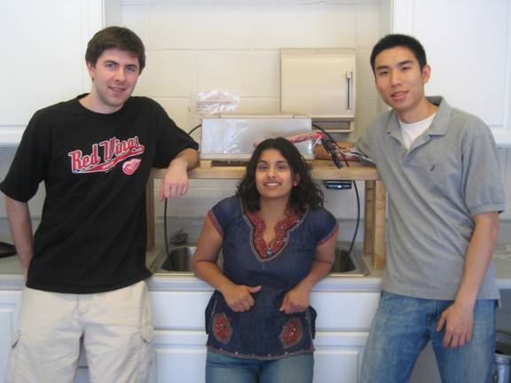
Tao Jin, Tyler Dolen, Vandya Swaminathan
“Have the Bellagio in your OWN HOME!!”
Introduction:
Our final project is a musical water fountain loosely based on the fountain in front of the famed Bellagio hotel and casino. The basic idea of the project is to take an input from an iPod (or any sound source), sample the sound and break it down to different “sequencies” by Walsh Transform , then use the output to turn on various solenoid valves. We first used a two-stage low pass filter, and then performed Fast Walsh Transforms on the sound source to split the sounds into different frequency ranges. Each different range will correspond to a different valve which comprises a musical water fountain operating to the beats and rhythms of the song.
High Level Design:
Currently, we have split the sound source into eight frequency ranges. The reasons for eight fountain heads are: 1- aesthetically appealing and 2- there are 8 pins for a standard I/O port on the Atmel Microcontroller. Since the purpose of this final project is to create a water fountain, we needed a pressurized water source. Originally, we had thought about using fish pumps; but then realized they did not have enough pressure. The pressure coming from the sink is between 30 and 40 psi, and therefore we decided to attach our input source to the sink. See below (Fig. 1) for a block diagram of our high-level design:
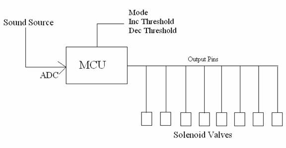
Fig. 1 – High-level design of the “Musical Water Fountain”
The entire project can be placed on a wooden stand which rests over the sink, so the water will drip back into the sink and not splash all over the area around the project. The following diagram in Fig. 2 illustrates the design of our water fountain system.
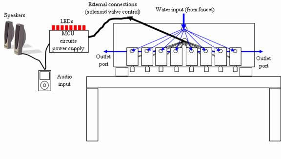
Fig. 2 – Preliminary Design
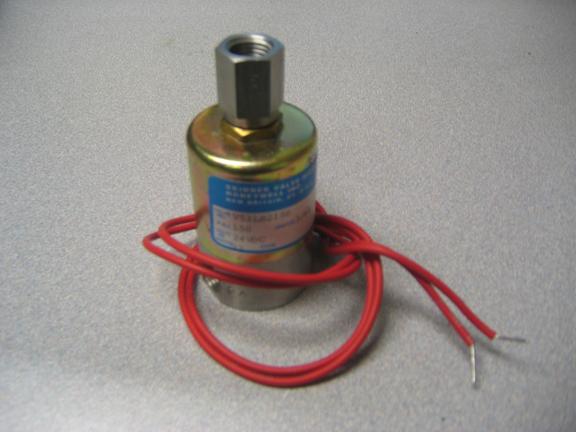
Fig. 3 – Skinner Solenoid Valve
There are a few important functions we needed to implement in our project. At the start of our project, the sound source was sampled using the A/D converter on the Atmel microcontroller. From the A/D converter, the samples undergo a Walsh transform (implemented in software) to split the samples into various frequency ranges. From there the individual ranges activate the different output controls, which correspond to the opening and closing of the solenoid valves. The output controls can also activate the specific LEDs that correspond to the activated valve. In this manner, a user can both see the valves turn on and the corresponding LEDs light up. We also have pushbuttons to control the mode (single or multi) and to change the threshold.
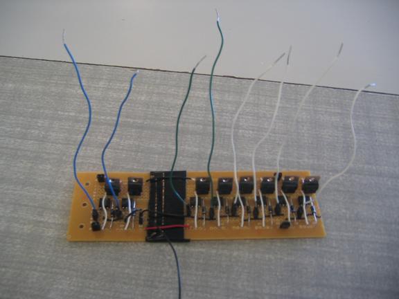
Fig 4: Optoisolator circuit for safety concerns
There are a number of safety issues that we have to contend with in the implementation of our mini “Bellagio fountain”. Additionally, there are many user specifications we must also decide to minimize the safety risks. The obvious issue for our project is water damage. Most of our components cannot be mixed with water. Water will short out most of circuitry, and even cause minor electrical shock to the unlucky person standing near the project if this were to occur. We must ensure the water is separated from the electrical components with superior insulation. In order to do so, we decided to both electrically isolate the valves using the optoisolator circuit (see Fig. 4) and point the valves downward. The pressure needed to activate the valves also caused the water to shoot too high, and water was uncontrollably hitting everything around the sink when the valves were pointed upward.
Program/Hardware Design:
Software
One of the most difficult parts of our program was determining which transform we should use. Originally, we had decided to use the Fourier Transform, because we felt we understood it the best. However, the Fourier transform took too many cycles, and was not fast enough. We then had to determine whether to use the Fast Fourier transform, which splits the sound waves into different frequency ranges, or the Walsh transform. The Walsh transform is faster, and much easier to code; in fact Professor Land had already written a basic Walsh transform which we could modify for our purposes. Unfortunately, the Walsh transform does not directly break up the sound waves into frequency ranges. Instead, it breaks up the sound waves into sequency ranges, which has a linear relationship to frequency ranges. Rather than sine and cosine, the ranges are broken into cal and sal equations. The result is often thought of as "a poor-man's fast Fourier transform (FFT)" representing the conversion of a time-sampled signal into an equivalent frequency-sampled form. Every range has roughly 150 Hz frequency range. In the end, we chose the Walsh transform, due to its speed.
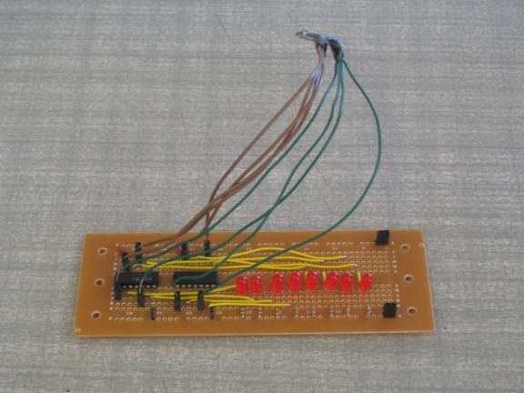
Fig. 5: LED circuit
Another issue we had to deal with was how many valves should be activated at any given time. Originally, we had determined to only activate one valve at a time, due to concerns about water pressure. However, when we received Professor Land’s test code (which was designed for LEDs) multiple LEDs would turn on at any given time, and the result looked very good. We could not determine which mode was better, and so we implemented a button which would change the mode between single and multi. In single, only the sequency band with the most information would have its valve and LED activated. In multi, any sequency bands which have a content value above a certain threshold would light up.
Different songs respond better to different threshold values. If the song is a particularly muted song, a high threshold will allow no LEDs or very few to be activated. However, if the threshold is too low, all the LEDs will be activated. A default value of 40 was set for the threshold, but two buttons were implemented to allow the threshold value to be changed so all songs would be implemented correctly in our program.
For TCCR0 our prescalar is 64. This means that every 250 ticks in the program counter corresponds to one millisecond. Being that our OCR0 also equals 250, this means the program will call the interrupt compare handler every millisecond. While we check the ADC and update our Walsh transform values, we do not update the LEDs or the valve controls every millisecond. We only update these every 200 milliseconds, as the switching time for the valves would then be too much and the valves would not function properly.
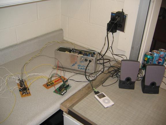
Fig. 6: Electrical Components
Circuit
The sound source or music can be fed from any standard player (mp3, cd, walkman, pc) with the 3.5mm stereo phone jack. We used a simple 2-to-1 splitter so the music can be played through a speaker and inputted into the Analog to Digital Converter (ADC) port of the microcontroller at the same time. The sound source from a standard player (ex. mp3) can not be directly used for ADC because the output signal maximum amplitude is usually +/- 1.5 V. The input signal therefore needs to have a DC bias which eliminates negative voltages and still stay within the range of the ADC reference voltage of 5V. Even though the audible range of a human ear is 20Hz-20kHz, we decided to sample the music at 2kHz to allow for fast ADC conversion and simple breakdown of frequency ranges. At this sampling rate, we can detect tones at up to 1kHz which will cut off high frequency treble sounds but still be useful for decoding typical music. As a result, we low pass filtered the input signal through two stages for sharper cutoff at 1kHz, removed the DC component of the sound source, and then biased the signal at 2.5V. The following Fig. 7 shows the input circuit:
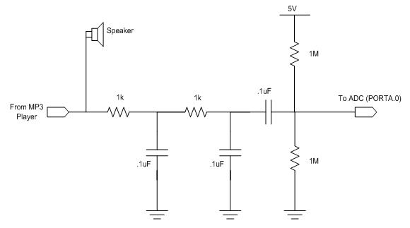
Fig. 7: Low Pass Filter and DC Bias circuit
We added additional functionality to our project by allowing the user to select the mode of operation for our valves and change the threshold values to produce the best pattern for the type of song playing. The three push buttons are “Mode”, “Threshold Up”, and “Threshold Down”. The default mode is set at single valve operation and the default threshold at 40. Pushing the Mode button will toggle between Single and Multi valve operation. The threshold value can range from 10-80 with a change of +/-10 depending on which button is pressed. All three push buttons have 20Kohm pull-up resistors and are soldered on to the protoboard.
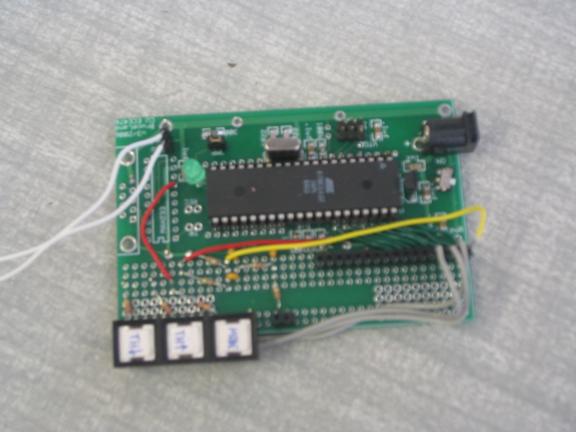
Fig 8: Atmel Microcontroller with Push Buttons
The output circuits consist of the LED display and the optoisolators for the On-Off control of the eight solenoid valves. Port B of the Atmel microcontroller is used as the output controls for both the LED and the valves. The LEDs and solenoid valves are arranged in Walsh Transform sequency order. We wired the LEDs and their respective valves from lowest sequency or frequency order on the left to the highest sequency range on the right. Since the valves are normally open, the LEDs and the valves need to turn “on” when the corresponding output pin is low. The use of inverters are needed to light the LEDs when the output is low. Optoisolators are used for each solenoid valve so they can be driven by 24V power supply and also isolate the MCU from potentially harmful inductive spikes. Fig. 9 is a circuit diagram of the output controls and LED displays.
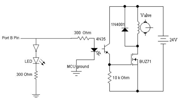
Fig. 9:Output Circuit (LED and Optoisolator)
Hardware
Fig. 10: Hardware Setup
Figure 10 shows a photo of our musical water fountain. For a water source, we use any standard kitchen/bathroom sink. A three stage adapter screws into the faucet connection and reduces it to 3/8’’ ID poly tubing. This tube is then sent into a port on the back of our container. Figure 10 is a diagram showing how water is distributed to the eight valves. After the first T splitter, the tubing is reduced to 3/16’’ ID. This size is based on the adapters and splitters we were able to sample free of cost. We also felt that since the input 3/8’’ tubing is being split eight ways, reducing the tube size would help maintain water pressure, which was an ongoing concern. The design is fairly straightforward – coming in with single tube, the water is divided using T splitters into 2, 4, and then 8 different connections. All T splitters and connections to the valves are quick connect fittings, which as the name states are much easier than using barbs and hose clamps. At first we were concerned, but the quick connect fittings are strong enough to handle our water pressure, and we had no leaks from these at any point during testing.
The valves used in our project are 3-way, which was not our original design. We originally planned on having 2-way valves, and a separate, single outlet control for the water in case all valves are off. However for these 3-way valves when a voltage is applied, any water being pumped to the input is sent out the third port. Another set of quick connect adapters is screwed into these outlet ports and connected in similar fashion to the inputs, with a separate outlet tube for each set of four valves. This system adequately handles water and prevents leaks when water is on, but all valves are turned off.
Another decision we had to make was how to secure the valves to our plastic container, ensuring that only the output tip would be outside the container. Each valve came with an adapter screwed on the top output port (see Figure 10). We decided to cut a hole in the top of the container small enough that the tip of the valve would stick through the lid. Then screwing the adapter on from the outside locks the valve into place. Eight equally spaced holes were measured and marked, and the eight valves fit in the container perfectly. At first we were unsure how to cut the holes in the lid, since the plastic can shatter when cut. Based on a suggestion from Professor Land, we heated a nail and used it to burn the holes in the lid. After using a knife to clean up the edges, we had eight properly sized holes to secure the valves onto the lid. The benefit of this setup is that no additional adapters or tubing are needed in order to visibly shoot water from the container.
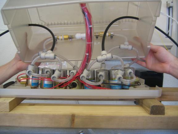
Fig. 11: Valve Setup
One notable feature of our project is that it was originally planned as a fountain that would shoot water up in the air from the valves, and then have it fall back down into a collection container. As will be discussed below, we were constantly plagued by water pressure difficulties. The eventual solution to this problem was, among other things, to turn our “fountain” upside down and have the container be directly above the sink and shoot water down instead of upward (See Fig. 11). With the aid of gravity, there is enough pressure to prevent the valves from being plugged and failing to re-open. This shift in our design was caused entirely by the nature of the valves, and we are confident that with more ideally suited valves, our initial design of an upward fountain would have succeeded. Because our valves now shoot down instead of up, there is no need for a collection container. By positioning the container above the sink, there is very limited splashing. As it turns out this design is cleaner and safer than our initial design. In order to position the contain above the sink we constructed stand from 2x4s that sits on the counter level with the sink, and the container rests approximately 16 inches above the counter.
Evolution of Our Design
The implementation of our design underwent numerous revisions over the course of the project. First off, the solenoid valves we were able to obtain cheaply were much heavier duty than what we had planned on. Initial testing with our most powerful fish tank pump (~ 250 gallons/hr) hooked up to just one valve showed that we did not even have enough water pressure to power a single valve. The minimum pressure to have the valves shoot water out was higher than we could generate, and purchasing more pumps would cause us to far exceed our budget. To solve this problem, Professor Land suggested that we use a kitchen faucet to provide water to our valves. The line pressure for indoor plumbing is around 30 psi, far greater than what we could generate with a fish tank pump. Testing with the faucet hooked directly to a single pump, we found even turning the faucet on a little water would shoot to the ceiling. We thought our pressure problems were over.
Fig 12: Original Hardware Design
However this solution created a new problem - the need for an outlet for the water being pumped into the system. Fish tank pumps have an automatic shutoff, so if all the valves are closed, the pump senses the feedback and shuts off. This prevents the pump from continuing to pumping water into the tubing. However the faucet does not have this feature. Once the faucet is turned on, water is being continuously pumped into the input port of the solenoid valves. However for much of the time (especially in single mode), water is not being allowed to pass out the top of the valves. Without an outlet port, the pressure would build up within our tubing and most likely lead to a burst connection. The first design we constructed is shown in Figure 12. Water enters the container and is split into two directions, one to each set of four valves. This was done because we felt that if a manifold of eight valves in series was created, there may be pressure difficulties farther down the line if, for example, the first few valves in the line were powered. Two sets of four valves in series should alleviate this problem to some extent. The final valve in each line is then connected to an outlet tube that returns the water to the sink. Since we had outlet tubes in the design, we decided to cap the third port of the valves to prevent water from flowing through when the valve is deactivated. The valves came with plastic caps, which we glued using a heavy duty waterproof adhesive. Unfortunately, testing this design we found that we still had problems with water pressure. The fountain would work to music for a little while (10-20 seconds), but then the pressure would fail to fully open the valves. Instead of shooting water in the air like a fountain, water would just dribble out of the top. In addition, when we attempted to plug our outlet tubes to test whether this would increase the pressure enough to open the valves, the pressure burst the glued caps out of the third port. This made us decide to use the third port as an outlet for each valve, and the water distribution was redesigned to the final method we used (described above).
Results of the design
video clip (22 Mbytes)
Speed of Execution
Our program cannot switch the valves instantaneously; there is a certain switching time which needs to be taken for the valves. We only update the valves every 200 ms, but even then there is a bit of a delay between the LEDs changing (which is practically instantaneous) and the valves switching. It becomes a slightly more prominent delay when the LEDs are placed next to the valves, but the only way to counteract his delay is to delay the output of the music somehow. Currently we have it playing straight to a speaker while it is being sampled; this is why the musical output is slightly faster than the rest of our outputs.
Accuracy
To test the accuracy of our Fast Walsh Transform (FWT) program we used the test code written by Professor Land which finds the maximum component of each sequency and displays the corresponding LED on the STK500. Since the FWT algorithm we used in this project does not take into account of the phase components of the signal, it is quite noisy from sample to sample even with a constant frequency input. Using the function generator to produce constant frequency signals with a peak to peak voltage of around 2V, we measured the rough frequency ranges of each LED output:
LED |
Freq Range (Hz) |
0 |
0-170 |
1 |
170-310 |
2 |
310-420 |
3 |
420-560 |
4 |
560-680 |
5 |
680-820 |
6 |
820-930 |
7 |
930-1000 |
As expected, LED0-7 each lit on in sequential order as the input frequency is increased from 0-1kHz. While the range varies for each LED output, there is roughly 100-150Hz difference in frequency between each order. As the input signal frequency is increased beyond 1kHz, the LED begin to cycle back down from 7. This is also expected since our sampling rate is at 2kHz which gives a maximum detection of up to 1kHz frequency range. Any higher frequencies will violate the Nyquist rate and result in aliasing in the frequency domain. Therefore a high frequency treble sound in a music signal will light up a low order LED and turn on the corresponding valve. While it is inconsistent, it does not really affect the goal of our project since the purpose of the valves is to operate according to the beat of the song being played.
Safety
Due to the nature of our project, combining electricity with spraying water, safety was an obvious concern and led to a number of our design decisions. We performed our initial testing of a fish tank pump and single valve in a bathtub, with all 3 group members present. One person held the valve to ensure water sprayed back into the tub, one controlled the power for the valve and pump, and the third held the wiring to the valve so it did not come in contact with any water on the floor. The person holding the valve also wore rubber gloves as an added precaution. Once we were sure the valves worked, the next stage of our project involved the coding, circuit design, and circuit construction. Since no water was involved, there were fewer safety concerns. The only safety measures needed were for soldering our boards, we used eye protection and caution with the hot soldering iron. When we came to final testing, spraying water became a safety concern again. We now had a 24 V power supply, two solder boards, a protoboard, and a significant amount of wiring. Testing in the ECE lounge kitchen, we had the electrical components on one counter and long wires running to the valve container by the sink. We used one giant salad bowl to cover the circuits and power supply, and another to direct the water being sprayed up by the valves. This worked surprisingly well at controlling the water, although the floor did get wet. Our final design is actually much safer than our testing stages. Once we made the decision to change our fountain to a water fountain and have water shoot downward, we eliminated the concern of water spraying and hitting the power supply and circuits. Also, since the minimum pressure to keep the valves functioning caused water to shoot around 4-5 feet in the air (compared to our initial hopes of only a foot), our design is definitely much safer facing downward.
Usability
The final version of our project is not quite as usable by others as our initial design. Our initial design was a single self contained unit, with a fish pump in the collection container supplying the water that would shoot up and fall back into the container. Once filled, it could keep running and be moved anywhere (power supply cord permitting). Our final design must be attached to a faucet, and must have some form of collection container below it that is connected to a drain. The easiest solution is how we demo it, positioned right above the sink that supplies the water. However aside from this constraint, our project is quite usable by both us and others. Any iPod or CD player is connected to the audio input with a standard speaker connection. The threshold value to activate the valves can be increased or decreased with a simple button push, so the project can be used with different volume audio inputs. There is no skill involved in operating our project – turn on the faucet, power supply, and audio input device, then watch the water fountain.
Conclusion
Our project evolved numerous ways over the course of the planning, execution, construction, and testing phases. However, the main goals and concept of our musical fountain (or water fountain) stayed the same and we were able to successfully achieve the desired results. While our end result did not come any close to the famed Bellagio water fountains in Vegas, we did have great satisfaction in building a water fountain (or fall) that can play to the beats and rhythms of our music source. We realized early on that some aspects of our project were too ambitious and we made the right changes to continue progress and ultimately accomplish the main goals we set in the beginning. For example, the solenoid valves we need in this project turned out to be very difficult to get because of their cost and the lack of free samples from valve manufacturers. Fortunately we were able to secure a lot of overstocked, outdated valves on Ebay for an extremely bargain price. Overall, this project turned out to be much more challenging and time consuming than we originally planned. A large amount of time was spent in mechanical engineering and construction on top of the circuit design, testing, and programming.
There can be many improvements to our final design since most of it was due to material, cost, and time constraints. The ideal case would be to use 2-way miniature on-off solenoid valves that can operate on low pressure. This way we can truly implement a musical water fountain that sprays up instead of down. The valves also need to have very fast response time to minimize the delay between closing and opening of the orifice. Further improvements can include increasing the sampling rate of our Walsh Transform and have more valves to expand the range of frequencies covered. We could also mount LEDs next to each valve to improve the visual effects of our project.
Ethical Considerations:
Patent 5439170 has a concept similar to us, but there is not enough documentation on how they implement it to see if it will gate us – All other fountain patents are not similar enough to our concept to prevent us from obtaining a patent. Most fountains have a pre-programmed, pre-choreographed valve control, rather than use the music itself to determine which valves turn on. Were we to have a larger budget, and perhaps a specific company backing, we could get a patent for our project
IEEE Code of Ethics:
1. to accept responsibility in making decisions consistent with the safety, health and welfare of the public, and to disclose promptly factors that might endanger the public or the environment;
Given that our project involves both water and electricity, we took very careful concern on safety and health issues. We made sure to protect all electronics from water contact, and even reversed the flow of our valves so water would not hit various people and items. We make sure anyone working near or on our project realizes the risks associated with it, and is extremely careful when standing near our project during actual execution.
3. to be honest and realistic in stating claims or estimates based on available data;
We have been very honest about the limitations of our project. We never lied about the physical reasons behind reversing the direction of the valves, and the delay between the water control, light control, and the actual music output.
4. to reject bribery in all its forms;
We accepted no bribes.
5. to improve the understanding of technology, its appropriate application, and potential consequences;
We specifically chose this project despite a lack of knowledge in plumbing and Walsh transforms. Using the internet and expert resources, we learned everything we needed to know, and sometimes even applied the knowledge in a different way to complete our project. We purposefully stepped out of our comfort zone in order to complete this project.
6. to maintain and improve our technical competence and to undertake technological tasks for others only if qualified by training or experience, or after full disclosure of pertinent limitations;
Due to the dangerous nature of our project, safety was always a concern. We made sure we bored holes in plastic near an open window to minimize smoke inhalation, and asked professionals or our mechanical engineering friends to cut wood so we did not loose any digits.
7. to seek, accept, and offer honest criticism of technical work, to acknowledge and correct errors, and to credit properly the contributions of others;
We used any help that was offered. Professor Land helped us with the code, and also offered suggestions for physical design. Alex Fee helped us cut wood.
8. to treat fairly all persons regardless of such factors as race, religion, gender, disability, age, or national origin;
Our lab group is extremely multi racial.
Appendix A:
Budget
Part |
Cost |
Custom PC Board |
$5 |
Mega 32 Chip |
$8 |
3/8” tubing (4 ft) |
$0.92 |
3/8” – ¼” barb adapter |
$1.52 |
4 Hose Clamp |
$2.36 |
Solder Board |
$2.50 |
2 Broken Solder Boards |
Free |
30V Power Supply for Valve |
Free |
Wood & Nails |
Free |
Plastic Box |
Free |
Opto-isolators, Resistors, Capacitors, Wires, Headers |
Free |
Power Supply |
$5 |
Quick Connects for Valves |
Free |
T-Connects |
Free |
5/16” tubing |
Free |
Sink Adapter |
$2.27 |
½’’ tube connecter |
$7.72 |
½” tube |
$0.33 |
8 Skinner 3-way valves |
$6.66 |
TOTAL |
$42.28 |
Appendix B:
Work Breakdown
Researching Valves/Pumps – ALL
Calling Companies for Free Samples – ALL
Debugging Code – TJ/Van
LED Circuit – Van
Optoisolator Circuit – Tyler
Input Circuit – TJ/Tyler
Building MCU Board – ALL
Shopping for Supplies/Research – ALL
Building Stand – ALL
Building Case for Valves – ALL
Connecting Valves & Tubing - ALL
Appendix C:
References
Data Sheets:
http://instruct1.cit.cornell.edu/courses/ee476/labs/s2006/LMC7111.pdf
http://instruct1.cit.cornell.edu/courses/ee476/labs/BUZ71.pdf
Websites:
www.kpiwebsite.com – Kelly Pneumatics
www.parker.com/skinner/ - Skinner Valves
www.ebay.com – Ebay
www.lowes.com – Lowes Home Improvement
www.homedepot.com – Home Depot
www.ithacaagway.com – Agway
Books:
Harwit, Martin, 1931- Title: Hadamard transform optics / Martin Harwit, Neil J. A. Sloane. Published: New York : Academic Press, 1979.
Sundararajan, D. Title: The discrete fourier transform : theory, algorithms and applications / D. Sundararajan. Published: Singapore ; River Edge, NJ : World Scientific, c2001.
Appendix D:
Code