 Automated Swing Robot
ECE 476 Final Project - Fall 2006
Done By : Hsiang Wei LEE (hl336) and Winson LIN (wl228)
Table of Contents
Introduction (top)
Everyone has played the playground swing since young at a point of time. So our final project will be to design a robot to simulate the swinging motion that brings us lots of joy during our childhood. The robot will extend and retract the leg while sitting on the swing. By using simple physics, the robot will swing on its own from rest to an angle of 90°. There is also an interface such that the robot can be switched to manual mode whereby a volunteer can attempt to it himself.
High Level Design (top)
Rationale (top)
This project was suggested during lecture by our Professor as he mentioned that a “swing robot” would be a cool final project. We liked the idea suggested by him and we modified it to suit the purposes of this project.
The Physics (top)
So what is the physics behind the swing? Since not everyone is a physicist, we will attempt to explain the motion using some simple physics. The swing works just like a pendulum, the period is only affected by the length of the rod holding the swing and gravity that we cannot really change. Therefore, we need to find some ways to change the amplitude of the swing arc.
One method to increase the amplitude is to create an addition forward momentum at the top of a swing arc. This can be done by swinging the legs forward when coming down from the top of the arc and retracting the legs backward when backing down from the other end of the arc. Assuming the loss of momentum to drag and friction is less than the momentum added in by the peak of the swing arc, the amplitude will increase with every swing.
The basic concept to increasing the amplitude is resonance. As the swing will be oscillating up and down at a certain frequency, the objective is to impart the external force into the system at the natural frequency. By doing so, the amplitude will increase with every swing.
Logical Structure (top)
Using the physics as discussed above, we will attempt to create a robot capable of swinging from rest. The basic structure can be summarized with the block diagram as shown below.
Figure 1. Block diagram
The Mega32 chip will be the ‘brain’ of the robot. It will be in-charged of moving the leg, which is the motor, so as to increase the amplitude of the swing. The ‘eyes’ of the robot will be the accelerometer that will be used to detect the peak of the swing arc. The movement of the legs will be coordinated so as to simulate a human being swinging as described above. The push buttons will allow human interaction with the system.
Program/Hardware Design (top)
The design can be broken down into two parts: the hardware section and the program section. The hardware design will include the pushbuttons/switch, accelerometer and servo motor. The program design will explain how the Mega32 chip coordinates the input and output of the hardware so as to start the swing from rest and maintain the amplitude. A picture of the custom board with all attached devices is shown below in Figure 2:
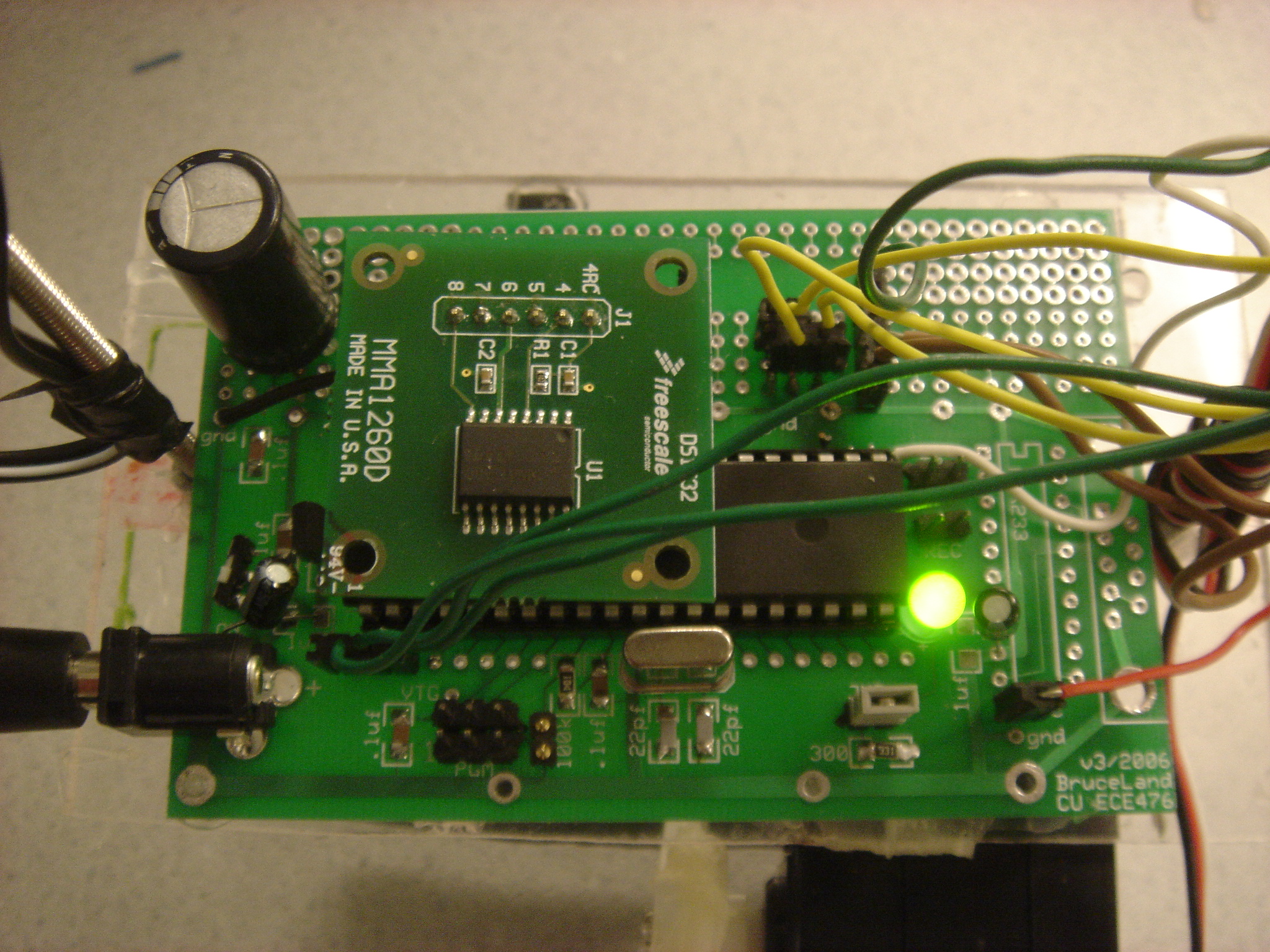
Figure 2. Custom Board with all attached devices
Push Buttons/Switch (top)
There are two objectives to this project. One is to create an autonomous robot that can swing itself from rest. The other is to allow a volunteer to play with the robot. Therefore, a switchbox is set up with three push buttons and one switch. The switch will turn on the robot system and the buttons will allow interaction with the robot. It can be seen below in Figure 3.
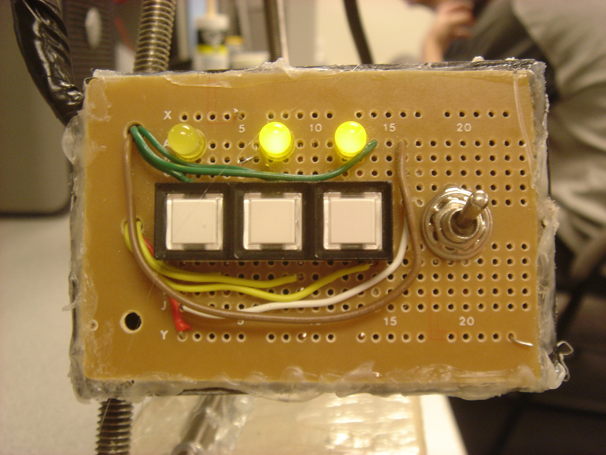
Figure 3. Switchbox
The three buttons serve the following functions.
-
Button 1: Get into auto swing mode. The robot will start swinging from rest and maintain the swing amplitude.
-
Button 2: Get into manual mode. The robot will stop swinging so as to allow human operation of the leg motor.
-
Button 3: Control for the leg motor. This button is only in effect when in manual mode. Pressing the button will result in the leg being extended. Releasing the button will result in the leg being tucked in
The default state is manual mode.
The buttons are debounced using the similar code structure that was used in the labs done over the semester. Debouncing the buttons is important as the buttons not only controls the mode of the swing, but it also controls the servo motor directly. If the buttons are not debounced, the servo will not be able to transit between the two positions smoothly, resulting in a significant amount of mechanical noise in the setup which affects the proper functioning of the accelerometer.
Accelerometer (top)
The accelerometer is used to detect the peak of the swing arc so that the robot can decide when to kick the leg. A donated z-axis accelerometer MMA1260D from Freescale is used to detect the acceleration in the z-axis. The three ports of the accelerometer are ground, power supply and output. The output is connected to a 100µF capacitor to reduce the noise.
Connecting the accelerometer to an oscilloscope, the output of the accelerometer is a sine wave whereby the peak of the swing arc will coincide with the peak of the sine curve. Using this as the motivation of the detection of the peak, a simple algorithm is written to determine the peak of each swing arc.
The output is connected to the ADC0 and is sampled every 40ms. The previous ADC value is stored and compared to the current ADC value. If the current value is greater than the previous one, a counter is incremented until a max number which determines the sensitivity of the peak detection. If the current value is lower than the previous one, the counter is decremented. The peak of the arc is detected when the counter is maxed and the current ADC value is less than the previous ADC value.
The accelerometer can be seen below in Figure 4.

Figure 4. Accelerometer
Servo Motor (top)
The servo motor is used in this robot to impart energy into the system. This part was purchased from Acroname at the cost of $10.90. The servo is a pre-modified potentiometer to adjust the center position and the specification is as shown below:
Specifications:
Size: 1.55 x 1.40 x 0.79in.
Weight: 1.48oz.
4.8-6v Speed: 0.23-.18 sec/60°
4.8-6v Torque: 47-56 oz- in.
The servo motor has 3 leads – GND, POWER and SIGNAL. The GND lead connects to the MCU ground, and a 5V potential difference is applied across the POWER and GND leads. The SIGNAL lead is connected to PORTD7 which is OCR2 which generates a PWM signal using timer2 of the Mega32.
To ensure that the servo motor can impart enough energy to the system, a weight of significant mass has to be attached to the servo motor which acts as the robots leg. The weight for this robot is a stack of 60 quarters, worth a total of $15.00. A figure of the servo motor attached with the weight is shown below.
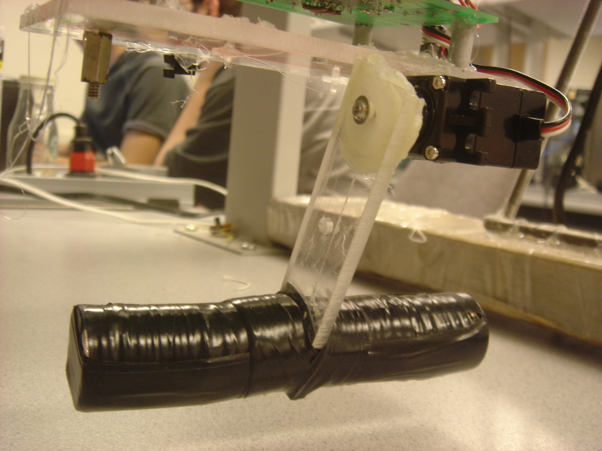
Figure 5. Servo Motor with the weight
Power Supply (top)
For this project, power supplies of 5V (for the servo motor) and 12V (for the custom board) are needed. The servo motor cannot be powered off the VCC on the custom board as the servo motor draws too much current then the voltage regulator mounted on the custom board as provide. Hence, the project uses the power supply which has outputs of both 5V and 12V. An image of the power supply is shown below on Figure 6.
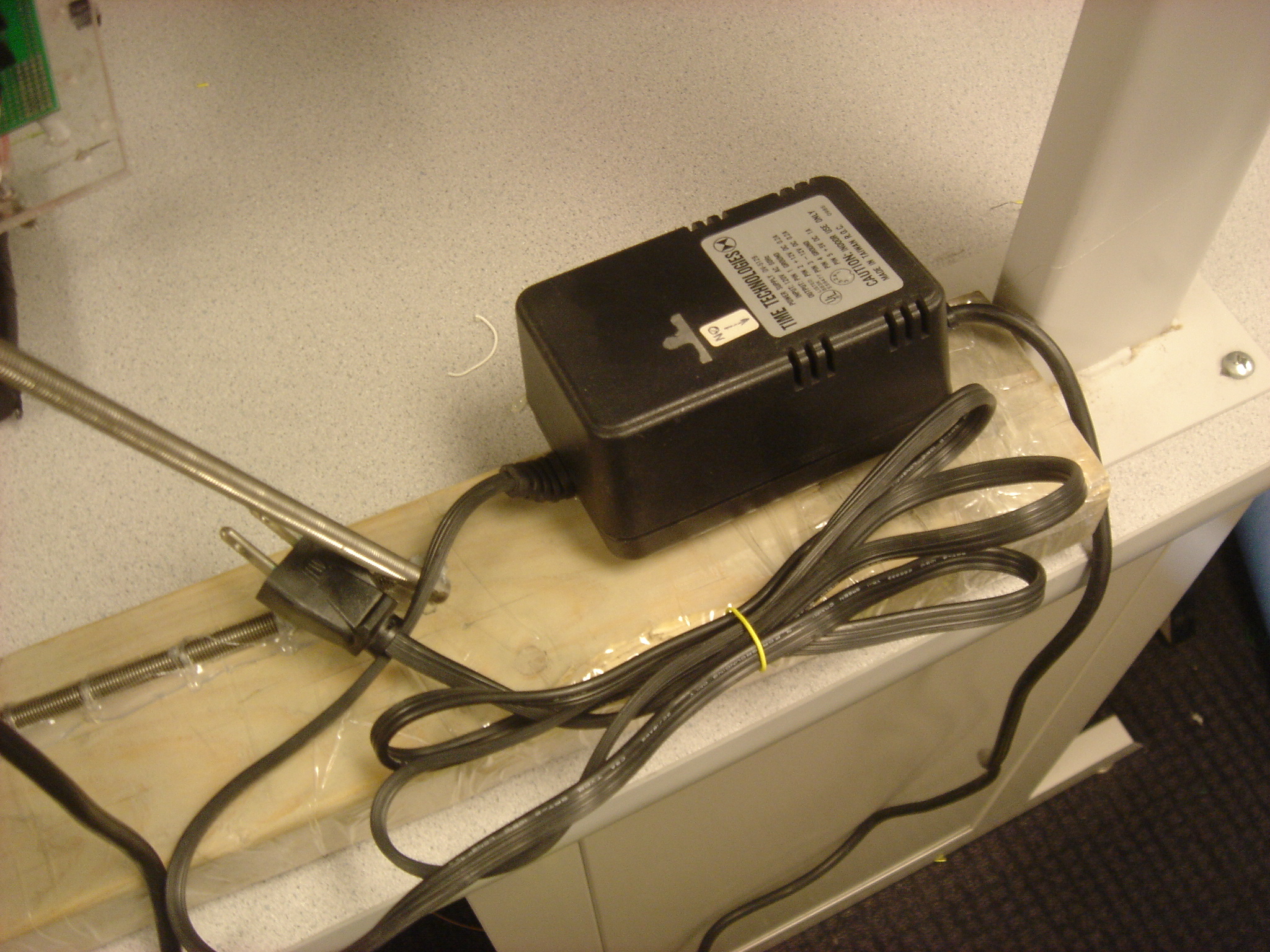
Figure 6. Power Supply
Program Design (top)
Using the input of the accelerometer, the servo motor has to be controlled such that the robot is able to swing itself from rest to the maximum amplitude and then maintain the amplitude. The program design can be broken down into two parts: swinging from rest and maintaining the swing.
Swinging from rest is difficult for the robot because it cannot push off the ground like what we usually do at the playground swing. Therefore, we have to make use of the principles of resonance to swing from rest. Furthermore, the accelerometer is not sensitive enough to detect a change if the change in amplitude is small. Therefore, by swinging the robot from rest at the natural frequency, the amplitude will add up with every swing until it is high enough for the accelerometer to detect the motion. So, we have to first determine the natural frequency of the swing.
We do this manually by swinging legs at a certain speed such that the amplitude adds up. By determining the period of each swing such that the amplitude will add up, we can determine the natural frequency. However, the natural frequency changes with amplitude. Therefore, we timed a few repetitions of the kicking and tucking motion of the servo motor whereby the amplitude of the arc increases. These timings were then used by the robot to start the initial swing.
Maintaining the swing is a matter of detecting the peak, kicking and tucking in at the respective peaks. Since the initial swing will bring the arc to an amplitude high enough for the accelerometers to detect the peaks, maintaining the swing is just simply changing the pulse signal of the servo motor at the peaks.
The final product is a robot that can swing itself from rest and maintain the swing arc. The swing and the robot can be seen below in Figure 7.
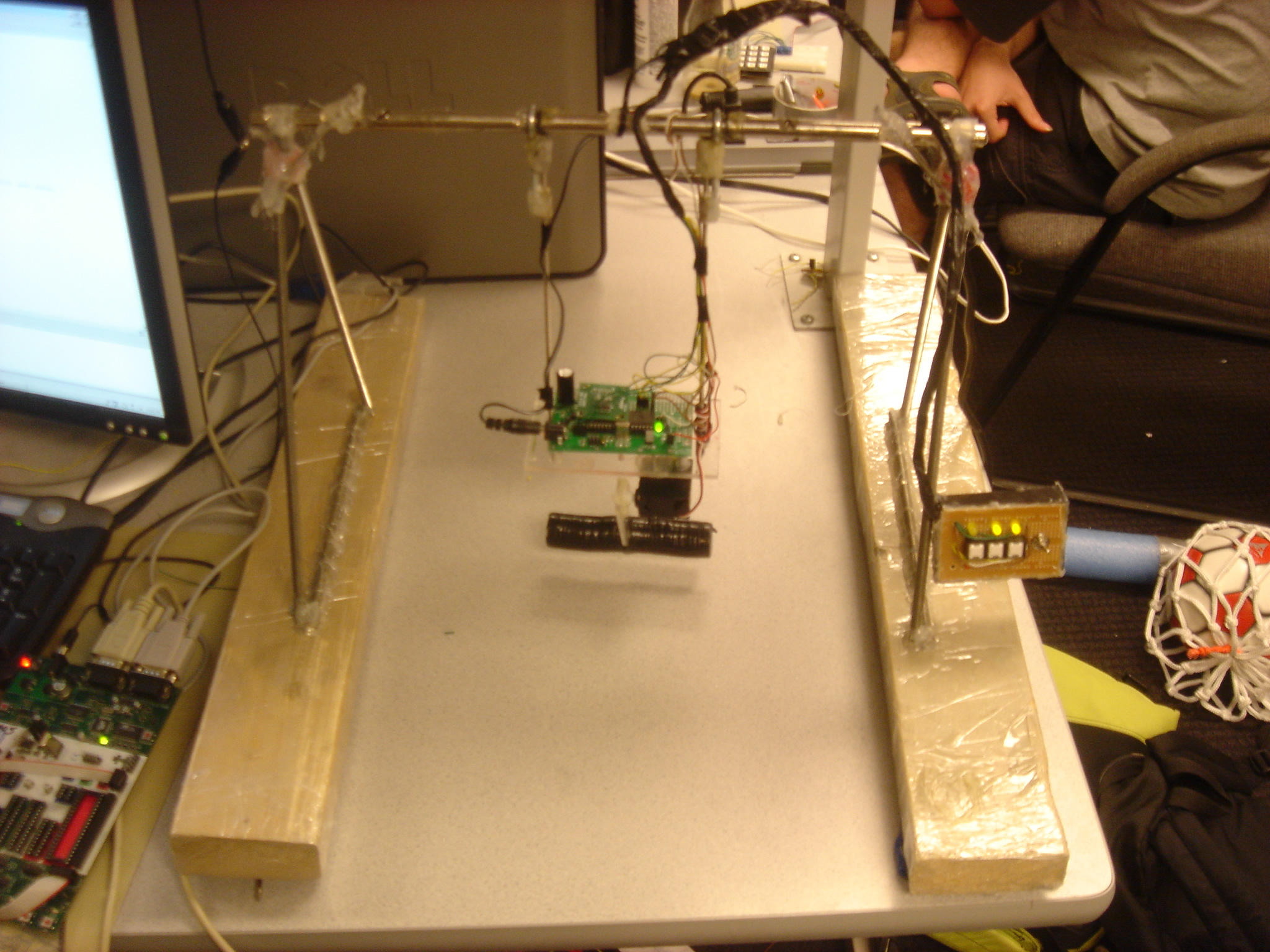
Figure 7. The Swing
What did not work (top)
There are some difficulties faced during the course of making the robot work. One of the difficulties is to provide sufficient power to the servo motor and yet ensure that it is not drawing from the same 5V source as the Atmel32 chip. We tried using 9V batteries but the motor drew too much current. In the end, we used a single power supply that provided both 12V and 5V across its terminals.
Another problem is the noise from the accelerometer output. The effect is especially pronounced for the xy-axis accelerometer. In the end, we have to use a big capacitor to reduce the noise. The drawback of using a big capacitor is a slight delay to the response time because it takes time to remove the charges from the capacitor. However, the short delay is not significant.
The initial design of our project involved the use of solenoids together with the servo motor. The concept of using solenoids was to alter the swings centre of gravity with respect to the axis of rotation, raising it at the bottom of the oscillation and lowering it at the peaks. However, we were unable to get this concept to function satisfactorily as the solenoids that we had provided insufficient displacement and strength. In an attempt to get this concept to work, we attached a 30V across the solenoids with weights attached to them. This, at best, prolonged the oscillation of the swing but the unwanted mechanical vibration that came along with it outweighed its benefits.
Result of Design (top)
Reaching Target (top)
We have been able to reach the target set for the final project by implementing a swing robot that can increase the swing amplitude and then maintaining it. Furthermore, the user interface is set up so that the servo motor can be operated by anyone. We went beyond the basic target by swinging the robot from rest.
Usability and safety (top)
To enhance the usability of the robot by the users, a swtichbox is used to change the control settings of the robot – between user control and microcontroller control. In addition, to ensure the safety of the user, a switch to turn on and off the power to the robot at a moments notice is equally important. This feature of the project can be seen in Figure 3 above.
Accuracy (top)
Accuracy of the robot is not a major issue in this project due to the different timescales between the swing and the microcontroller. Each tick of the microcontroller is set to run every microsecond, while a single oscillation of the swing robot takes about 1 second on average. This difference in timescale is of 3 orders of magnitude, hence it does not affect the functioning of the robot in any discernable way.
Conclusion (top)
We achieved our target of swinging the robot from rest and maintaining the amplitude infinitely. A user interface was added to the robot so that other people can have their hands on the swing.
Areas of Improvement (top)
Given more time, there are some improvements that can be made to the swing robot. One of them is to be able to continue the swinging motion when the user decides to stop swinging halfway and switch to auto swing mode. Currently, the swing robot is programmed to swing from rest.
Another improvement is to implement a wireless control system so that the amplitude of the swing would not be hindered by excess wires. With the existing setup, there are many wires connecting the switchbox to the board. This resulted in unnecessary dampening of the motion and hence the amplitude could not be further increased.
Ethical Considerations (top)
We, the members of the IEEE, in recognition of the importance of our technologies in affecting the quality of life throughout the world, and in accepting a personal obligation to our profession, its members and the communities we serve, do hereby commit ourselves to the highest ethical and professional conduct and agree:
1. to accept responsibility in making decisions consistent with the safety, health and welfare of the public, and to disclose promptly factors that might endanger the public or the environment;
There are no safety issues with the swing robot since the only human interaction will be through the switchbox which is properly insulated against any electric shock.
2. to avoid real or perceived conflicts of interest whenever possible, and to disclose them to affected parties when they do exist;
There is no conflict of interest of any sort.
3. to be honest and realistic in stating claims or estimates based on available data;
Everything is real and no data has been made up.
4. to reject bribery in all its forms;
No bribery has been offered to our team members.
5. to improve the understanding of technology, its appropriate application, and potential consequences;
The report describes everything to our fullest possible capabilities.
6. to maintain and improve our technical competence and to undertake technological tasks for others only if qualified by training or experience, or after full disclosure of pertinent limitations;
We are able to apply what is learnt in the classroom into daily life application like a playground swing.
7. to seek, accept, and offer honest criticism of technical work, to acknowledge and correct errors, and to credit properly the contributions of others;
Acknowledgements are given in the appropriate section.
8. to treat fairly all persons regardless of such factors as race, religion, gender, disability, age, or national origin;
Everyone is treated fairly without any prejudice.
9. to avoid injuring others, their property, reputation, or employment by false or malicious action;
No one was hurt throughout the course of the project. A team member was burnt by overheated chip but was attended to immediately.
10. to assist colleagues and co-workers in their professional development and to support them in following this code of ethics.
Groups doing similar projects were able to build on some of our experience. Our concept of using the servo enabled the 3 groups doing the swing to move forward in the project together.
Acknowledgements (top)
-
Freescale, www.freescale.com – For donating their accelerometers
-
Dr Bruce Land and his team of TAs – For their help during lab hours
Appendix (top)
Cost (top)
The cost of the project was kept under the budget imposed budget of $50. The table below shows the breakdown of the costs involved with the project.
Part |
Cost |
Description |
Solder Board |
$2.50 |
- |
Mega32 |
$8.00 |
- |
Power Supply |
$5.00 |
- |
Custom PC Board |
$5.00 |
- |
Accelerometer Z-axis |
$0.00 |
Sampled from Freescale |
Metal Rods |
$0.00 |
Found - With help from a MechE friend |
Plastic Sheets |
$0.00 |
Found as scrap |
Acylic Sheet |
$0.00 |
Found as scrap |
Quarters |
$15.00 |
Used as Weights |
2 Pieces of Wood |
$0.00 |
Obtained as Scrap from a contruction site |
Total |
$35.50 |
|
Figure 8. Breakdown of Costs
Tasks (top)
| Task | Group Member |
| Accelerometer Interface | Winson |
| Servo Interface | Hsiang Wei |
| Swing Setup | Hsiang Wei |
| Switchbox / Wiring | Hsiang Wei |
| Soldering | Winson/ Hsiang Wei |
| Testing | Winson |
| Report | Winson/ Hsiang Wei |
| Website | Winson/ Hsiang Wei |
Figure 9. Breakdown of Tasks
Schematic (top)
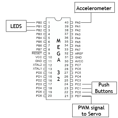
Figure 10. Schematic of Project
Datasheets (top)
Websites (top)
-
Further Physics of a Swing - http://www.hk-phy.org/articles/swing/swing_e.html
-
Physics of Everyday stuff - http://www.bsharp.org/physics/stuff/swings.html
Videos (top)
-
Video of Swing Starting from Rest ( warning--72 Mbytes)
-
Video of Swing (Side profile) (20 Mbytes)
Code (top)