 Para Para Revolution
ECE476 Final Project, Spring 2006
by I-Chun LI (IL45) and Chia-Hsuan Tsai (CT264)
Introduction
Para Para Revolution, P2R, is the dancing game that players wear gloves with acceleration sensors to wave their hand and present directions.
P2R is a dancing game which is similar to Dance Dance Revolution (DDR). DDR is played by feet position; however, the dance of P2R focuses on both hands¡¦ waving. This kind of dance is called Para Para, which is very famous in Japan. Like DDR, our Para Para Revolution (P2R) is a music-based game. The player has to follow the rhythm and wave his hand in a certain direction. It may require players to wave their hands in different direction. So, P2R can train players to be more harmonious in their body motion.
Introduction
High
level design
Software
Design
Hardware
and its related software design
Result of
the design
Conclusion
Code
Other
schematic
Appendix:
Cost detail
Appendix:
Specific task
Appendix:
Reference
Appendix:
Gallery
High level design (top)
Sources of the project idea
DDR has been a famous video game for a long time. After DDR was created, Para Para Paradise was also famous as another kind of dancing video game. They are both commercialized and hit great success. Dancing is human nature and is a good exercise. To create a dancing game will always be an exciting job.
Software/hardware structure and trade off
The software structure diagram:
The detail will be discussed in the software design part.
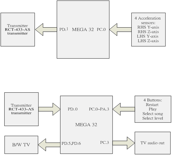
The conceptual hardware structure:
Basically, we want to use a single mcu to accomplish all jobs. However the performance may be restricted by the video part because it has to draw every line in a stable time, and there would be less remaining time to operate other functions.
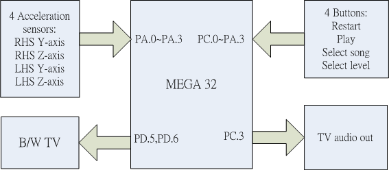
The sensors' inputs use PORT.A as an A/D converter. It requires a state machine to run four sub state machines alternately. PORT.B is used to generate audio effect in PWM and output through TV speaker. A debouncer will debounce button inputs from PORT.C's and set the playing mode parameters. PORT.D is used to generate image to TV screen. It is the most basic structure. Actually, to use extra memory to store music in DMCP and to use wireless to transmit sensors signal are feasible. We were working on these and almost completed the critical parts just before the project deadline.
Existing patents and copyrights
Para Para Paradise is a register trade mark as a DDR-like video games. Therefore we chose Para Para Revolution as our game's name. Some songs are made by previous groups and we wrote E-mail to get their authorization, and we also comment this in our code.
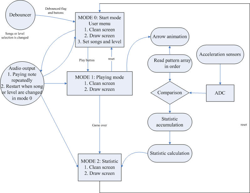
Software design (top)
Three modes of the main program
Our game contains three modes: start mode, playing mode and final statistic mode. In the start mode, players can select different songs and levels. When any different options is selected, the music will restart or change its speed. In the playing mode, there will be two arrows animation columns in the middle of the screen. The arrows will keep going up, when arrows reach upper blocks, the program will compare arrows pattern and the direction signals. There are three kinds of situation: perfectly match in the block, approximately match, and miss. The first two situations will be highlight as "PERFECT!" and "GOOD!", and the third will be "MISS!." The statistics for both hands are also shown in the screen. Finally, as the time up, the program will enter statistic mode, show both hands' hit rate, number of perfect, good and miss times, and total scores.
Button debouncer
For user menu, it require four buttons to restart the game, enter playing mode, select songs and select level. The restart button works for every mode and whenever it is pressed, the game restart. The other buttons require a 4 states debouncer just as our previous lab. When entering the debouncer, it will compare the whole button signals with previous ones. if they are different, it means a specific button is pressed. As soon as a button is definitely be detected, it will set a detection flag and the buttons signals and stop debouncing. After user menu mode used the button signals, the detection flag will be cleared and the debouncer can work again.
Video effect
We use Dr, Bruce Lands video generation code for with Atmel AVR microcontrollers for video display. When using full screen, the calculation ability is limited. It probably can only print less than twenty 5x7 characters in each frame time. To solve this problem, We divided a single task to many pieces and separated them into many frames.
For every mode begins, it is required to clean the screen first. It takes 26 frame times, 26/60 seconds to clean all the pixels on the screen. Then other characters, lines, animations are printed frame by frame, and then functions of these modes start. So, when changing to any mode, the draw screen functions for each modes will be called, a clean screen flag and a draw screen screen flag will also be set.
Moreover, we created a 7x7 bitmaps for arrows and logos and added some codes to display ":", "!" and space. Also, we create functions to highlight a regions and clear a regions in order to draw the screen and animations.
Audio effect
Our music design refers to Russian Bloc game in Spring 2002 Final Project. The songs' format contains a two dimensions array. The first array records notes, and the second array record the playing time for each notes. The program will play notes in order. The notes are made by the specified frequency of the musical notes, and use OCR0 as its PWM output. Whenever the song, the level (song's speed) or modes are changed, the counter of notes and its time will be reset, and songs will be played from the beginning. Otherwise, the selected song will be played according to the selected speed repeatedly.
Since the frequency of frames is 60Hz, the length of each note should be longer than 0.0167 second. We set a beat's length counter to 12, and the factors of level are 1 for hard, and 2 for rookie and basic. So, each beat's length is about 0.2 or 0.4 second.
Animation
The animation are the up-going 7x7 arrows:

Here is the snapshot of the playing mode animation:
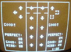
There three vertical lines in the middle to separate each hands direction arrows. For each hand, there will be at most five arrows show at the same time and set them into five sets. We used the size of five arrays to restore arrows pattern and each set's y-axis coordinates. There is a pointer points at the top arrows. When it's y-axis coordinate is less than 2 (the edge of the frame), the arrow will be erased, the pointer goes to the next pattern, and then load a new pattern in the pattern array and set the new arrow position to the bottom. Each of the fives sets of arrows will be erased, and then their next step y-axis position will be calculated, and then draw it again in a frame time. So, it requires five frame time to make all arrows go up one step. The step size is according to the level, and it can easily to be changed to make the game has more challenge.
There are three arrow patterns showed in each sides which will show the sensor directions. When any action is detected, the arrows of that direction will be highlighted as you can see in the above picture.
Comparison
The following snap shot shows the horizontal line number of the arrow animation region:
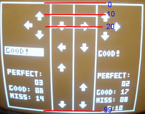
There are two lines in the upper side to enclose two block. The upper block is the passed arrow which will disappear. The following block is the compare space. When arrows reach this region, players have to wave their hands according to the pattern. There is an other variable to record these arrows y-axis position. When they match, the record for which the y-axis from 10 to 13 is perfect, from 7 to 9 and from 14 to 16 are good, and else is miss. Whenever a perfect or good match happens, a hit counter will be set to three. If the counter is zero, and the arrow passes through y -axis equal to 6, a miss will be shown and recorded. But why does it set this counter to three? As the counter greater than one, the detection message of that hand side will highlight and counter minus one. The highlight is to inverse the regions color. So, when the counter is set, it can be minus one for two times, and the highlight time will be two which means that the message color will be inversed and inversed again to make the blink effect. This effect shows in the left side message of the above picture.
Statistics
Every hits and miss data will be recorded for both hand: L_perfect, L_good, L_miss, R_perfect, R_good, R_miss, where R stands for right and L stands left. The hit rate formulas of each hands are:
L_hitrate=100*(L_good+L_perfect)/(L_good+L_perfect+L_miss)
R_hitrate=100*(R_good+R_perfect)/(R_good+R_perfect+R_miss)
And the formula of score is:
final_score=[(L_perfect+R_perfect)*4+(L_good+R_good)*3+(R_hitrate+L_hitrate)]*(4+(int)SelLevel)//
SelLevel is the level of the game from 0 to 2
The higher level will has higher
scores. We do not minus scores for miss because the sensitivity of the sensors
sometimes does not very well. The other reason is to prevent negative scores.
The calculation use multiply and divide; so, we divide the formula and print
screen to parts and calculate them in different frame time.
Hardware and its related software design (top)
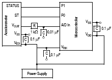
Acceleration sensor moduleThe external devices of P2R are acceleration sensors. There are one Z-axis and one XY-axis acceleration sensors for each hand. We use the ADC provided Mega32 to convert the signals. The ADC will convert each sensors input alternatively. Therefore, the mux of input channels will goes like this: ADMUX = 0b01100000àADMUX = 0b01100001àADMUX = 0b01100010àADMUX = 0b01100011 and then goes back to ADMUX = 0b01100000.
Basic concept of acceleration sensor module:
This module contains two similar circuits. One is the circuit for the left hand, the other one is for the right hand, as shown in figure A. Each circuit contains two different acceleration sensors----MMA1260QW for Z direction and MMA6261Q for Y direction. (Thanks Bruce and Freescale Corp. for these samples) The Z-direction acceleration sensor provides the movement information in the Z-axis. In other words, when the user raise up his hand, we can get the analog output depends on the speed and direction of the movement. Similarly, we can get the analog output from the Y-direction acceleration sensor.
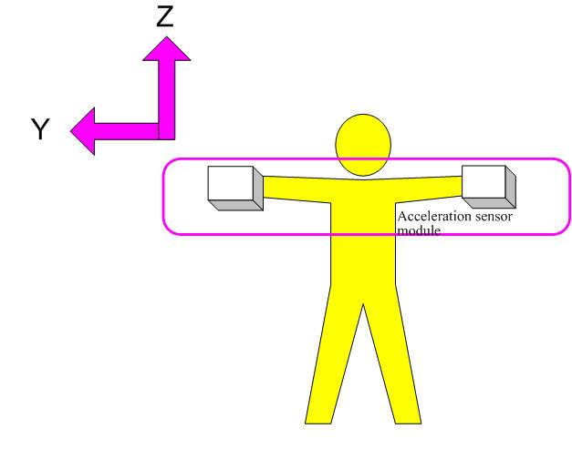
Figure A.
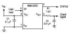
Behavior and state machine of MMA1260D (Z-axis acceleration sensor):
The Z-direction acceleration sensor is formed by two stationary plates with a moveable plate in-between. These plates could be considered as a capacitor. However, the capacitance varies with the movement. When the user¡¦s hand moves, the distance from it to one fixed plate will increase by the same amount that the distance to the other plate decreases. The change in distance is a measure of acceleration because the cut-off frequency reflects the capacitance and the capacitance reflects the acceleration.
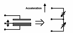
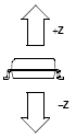
Figure B
Because of the effect of inertia, the relation between movement and output
signal is not straightforward. To get the relation between the movement and the
analog output signal of sensor, after many experiments, the behavior of this
sensor can be modeled as the figure C. The values indicated in figure C are the
approximately digital output, and these values vary with different movement or
acceleration (before analog to digital conversion, 1sb=1mV because![]() ). When
the user raises his hand, the out signal is not constant high. Instead, it will
be highàlowàhighàlow.
). When
the user raises his hand, the out signal is not constant high. Instead, it will
be highàlowàhighàlow.
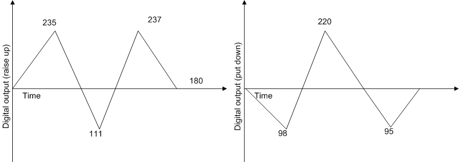
Figure C
In order to get accurate movement, we create a state machine for the Z-direction acceleration sensor. This state machine totally contains 7 states; the diagram for the state machine is shown in Figure D. After several states, we finally can determine the correct movement of hand in Z-axis.
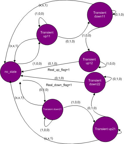
Figure D
Behavior and state machine of MMA6261Q (Y-axis acceleration sensor):
Figure E
The basic operation method of MMA1260QW acceleration sensor is similar to the MMA1260QW. Figure E indicates the interior plates for sensing the movement of X or Y direction, and figure F. indicates the behavior and the scale of digital output (before the A/D converter, 1sb=1mV) in the positive and negative Y-axis. If the movement is toward the positive Y-axis, the output will be highàlowàhighàlow because of the effect of inertia. Similarly, we need a state machine to determine the ¡§real¡¨ movement of the hand. As shown in figure G, we created a state machine with 5 different states.
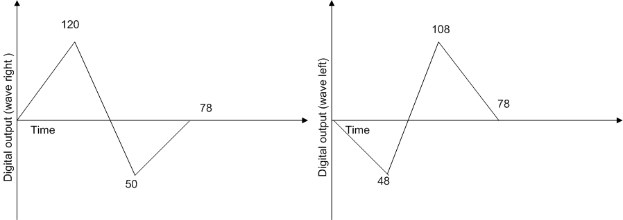
Figure F
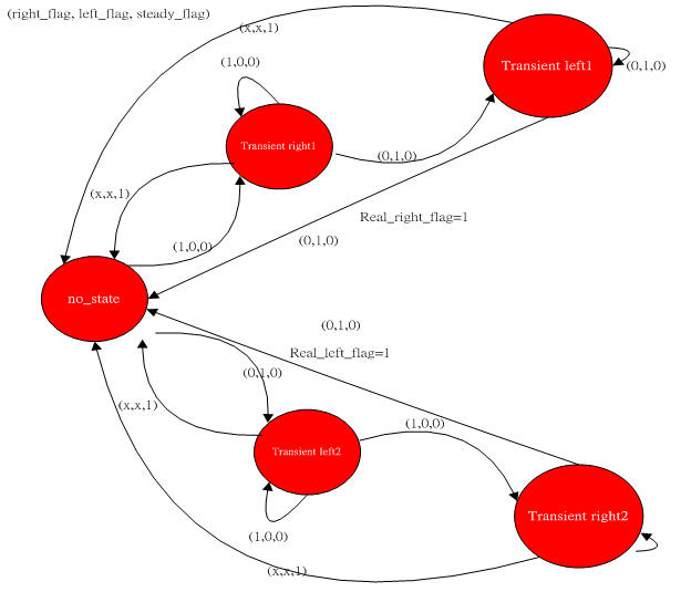
Figure G
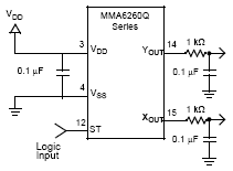
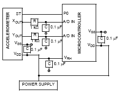
Schematic of acceleration sensor module
The DC power supply voltage for MMA1260Q (Z-axis) and MMA2260D (Y-axis) are 5V and 3V separately. We can easily get the 5V dc supply from our customized PC board or STK500, however, it is necessary to create a circuit for 3V power supply. Because the out resistance is quite large (MMA2260D has a big input resistance), it can not be made directly by series resistances as a voltage divider to do it. Instead, we utilized OpAmp LMC7111 to make a circuit to get 3V voltage source. The schematic for the DC supply is shown in figure H. After integrating MMA1260D and MMA2260D together, the schematic is shown in figure I.
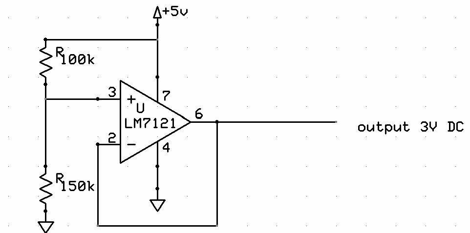
Figure H
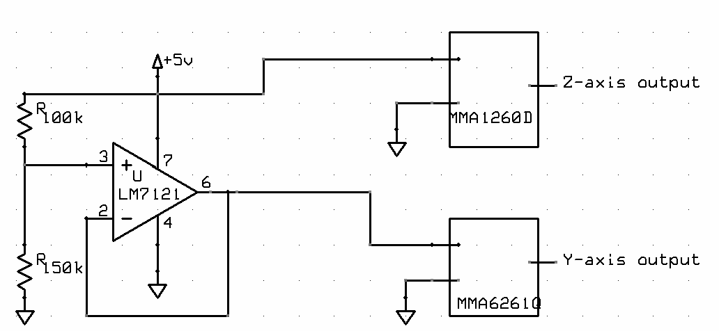
Figure I
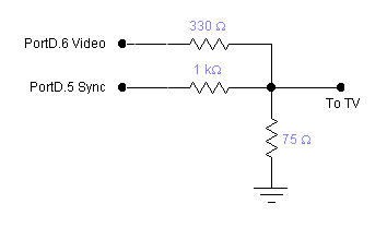
Video output
Our video module refer to Dr, Bruce Land's ECE476 lab4. the schematic is:
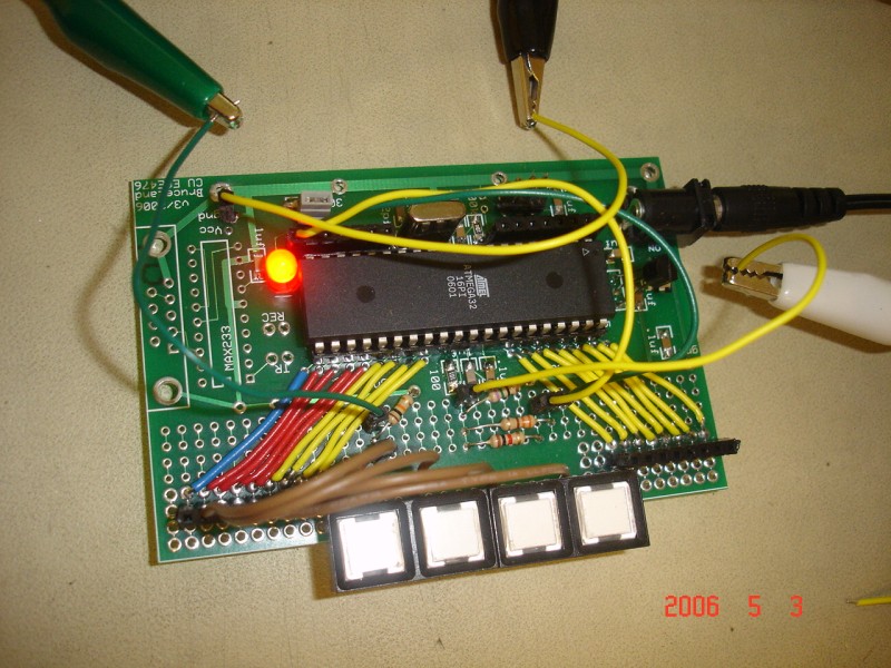
Customized PC board (worked before, but dead)
In our hardware design, we soldered a customized PC board:
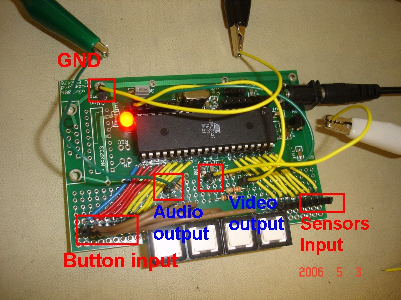
We solder every part in the customized board. As you can see, it contains audio/video outputs, sensor inputs and buttons. We could only use this small size board to demonstrate all of our works! However, It worked pretty well for a couple of days, and somehow it doesn't work when we load data in May 2, 2006. Therefore we put the picture here to memorize it.
Optional uncompleted part: wireless handset module
We are planning to create the handset with wireless module to make this game marketable in the future. For this reason, we made a pair of RF transmitter and receiver. Radiotronix RCT-433-AS transmitter and the Radiotronix RCR-433-RP receiver chips are used for this transmission. The OOK protocol is used for this transmission and the frequency is 433MHz. The transmitter will connect to the STK500 and transmit the encoded signal (encoded with 6 bytes data). Figure 1 indicates the connection of the wireless module and the system. In the aspect of data transmission, except the encoded signal, one data byte which contains the information about how the user¡¦s hands move will be transmitted. This original data byte consists of the following information---[Right hand ¡VY, Right hand-Z(up), Right hand-Z(down), Left hand ¡VY, Left hand ¡VZ(up), Left hand ¡VZ(down)]. Take the bit Left hand ¡VZ(up) for example, if a user raises his left hand, this bit will be ¡§1¡¨. If not, this bit will be ¡§0¡¨.The following table A is an example which indicates the original data transmitted to the receiver and the corresponding movements.
|
Data |
Right hand -Y |
Right hand-Z(up) |
Right hand-Z(down) |
Left hand ¡VY |
Left hand ¡VZ(up) |
Left hand ¡VZ(down) |
|
00000000 |
0 |
0 |
0 |
0 |
0 |
0 |
|
00100000 |
1 |
0 |
0 |
0 |
0 |
0 |
|
00001100 |
0 |
0 |
1 |
1 |
0 |
0 |
Table 1.
The schematic with wireless would be:
Protocol for wireless communication
To simply the communication with Mega32, we use 6 byte to encode the signal. Because we are still estimating the feasibility of the wireless module, we didn¡¦t include the transmitter ID byte. They are 4 bytes for synchronization, one start byte and one end byte. The following figure reveals the structure of data string. This part refers to Wireless Protocol by Meghan Desai.
|
Sync Byte (0xaa) |
Sync Byte (0xaa) |
Sync Byte (0xaa) |
Sync Byte (0xaa) |
Start Byte (0xca) |
Data Byte |
End Byte(0xd4) |
Transmit and receive data
USART TX
and RX ports are utilized for the transmitter and receiver. The Baud rate is
set as 4800bps (
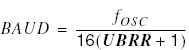 , UBRR=207)
which is suitable for the Radiotronix RCR-433-RP receiver chips (Maximun Baud rate
4800bps). We used USART to transmit
the signal. PORTD.1 is connected to the transmitter and PORTD.0 is connected to
the receiver. UCSRB.5 is set as¡¨1¡¨ to transmit the data with USART Data
Register Empty Interrupt. UCSRB.7 is set as ¡§1¡¨ to receive the data with RX
Complete Interrupt Enable.
, UBRR=207)
which is suitable for the Radiotronix RCR-433-RP receiver chips (Maximun Baud rate
4800bps). We used USART to transmit
the signal. PORTD.1 is connected to the transmitter and PORTD.0 is connected to
the receiver. UCSRB.5 is set as¡¨1¡¨ to transmit the data with USART Data
Register Empty Interrupt. UCSRB.7 is set as ¡§1¡¨ to receive the data with RX
Complete Interrupt Enable.
Results of the design (top)
Speed and accuracy of execution
The game can work fluently without any screen delay or flicker. The video line duration from the video code is 63.625us while the normal NTSC signal is >>63.55us. No flickers are observed due to this small inaccuracy. The audio is also running well. The only problem is that the hand waving signal will have some delay to the real motion because the it takes 4 frames, 1/15 second, to enter the next state. Players have to practice and get familiar with the delay. After training, we can almost get 90% hit rate for each hand.
Interference with other
people's designs
Now, we have not met this problem. If we make the wireless part works, we will consider about this.
Enforced safety in the design
All the metal and solder are isolate with human body. The sensor circuits are put outside the nylon gloves, and wires are wrapped in the cable.
Usability by you and other people
The acceleration sensors models successfully transfer "acceleration" signals to "direction" signals. The delay problem can be solved while using faster interrupt. Other people can easily modify the state machine to do 3-D directions works.
Conclusions (top)
Improvement: better sound effect
Actually, we were planning to use DMCP which may require external memory. Since the original mcu can only work at 60 Hz (after a frame finish drawing), it require an extra mcu to play the sound and be triggered by external interrupt from the original one. We had already tested this part, but the extra memory that we used is SD card require more effort.
Improvement: more accurate direction sensing signals
Alternatively determine each sensor takes longer time. The better solution will be used individual external ADC for each sensors.
Improvement: more beautiful image and animation
It is always a problem for w/b TV. Some group had made color TV platform which may be useful.
Improvement: wireless hand set
As mentioned above, it is in progress.
Improvement: multi-user
Maybe multi-TV, right?
Conclusion of improvement
Almost all the above improvement ideas are feasible. ECE476 indeed lets us understand more possibility of our daily life.
Intellectual Property Considerations
All the reused code and idea we referred are list in the reference.
IEEE Code of Ethics
1. We accept resp
3. We maintain and improve our technical competence and to undertake
technological tasks for others only if qualified by training or experience, or
after full disclosure of pertinent limitations.
4. We seek, accept, and offer honest criticism of technical work, to
acknowledge and correct errors, and to credit properly the contributions of
others. All the references related our project are disclaimed in this page and
our code.
5.We try our best to treat fairly all persons regardless of such factors as
race, religion, gender, disability, age, or national origin. Our video game can
be played by anyone as long as he/she can move parts of his/her body.
6. We guarantee avoid injuring others, their property, reputation, or
employment by false or malicious action as long as they use our thing properly.
7. We agree to assist colleagues and co-workers in their professional
development and to support them in following this code of ethics.
Conclusion of the project
To apply what you learn to practical work is always exciting. Microcontroller is indeed a great toy.
Code (top)
p2r.c: Main program
song.c: Audio effect
handadc.c: sensors' state machines and ADC
drawscreen.c: clear and draw screen
video.c: For video display and effect
font.c: bitmaps of characters, arrow patterns and logo
Other Schematics (top)
schematics of sensors:
XY-axis sensors. We used the right side customized board built by Freescale.
Z-axis sensor. We used right side customized board, too.
Other schematics are all described in the previous paragraph.
Appendix: Cost details (top)
Mega32 free sample from
|
Part |
Unit cost |
Quantity |
Total cost |
Comment |
|
AVR Mega 32 |
free |
1 |
0 |
Free sample from Empire Technical Associates |
|
B/W TV |
5 |
1 |
5 |
|
|
MMA1260Q |
free |
2 |
0 |
Free sample from Freescale |
|
MMA2260D |
free |
2 |
0 |
Free sample from Freescale |
|
White board |
6 |
1 |
6 |
|
|
Custom PC board* |
5 |
1 |
5 |
|
|
Cable |
0 |
1 |
0 |
Get it from home |
|
Power supply |
5 |
1 |
5 |
|
|
Gloves |
0 |
2 |
0 |
Get it from home |
|
|
|
|
|
|
|
Total |
|
|
21 |
|
*We had a workable custom PC board, but it dead before check out. So, we actually used STK500.
Appendix: Specific tasks (top)
I-Chun Li (IL45):
Main program development and maintenance.
Music and sound effects.
Customized PC board (worked before, but dead).
Chia-Hsuan Tsai(CT264):
Acceleration sensors hardware design and soldering, and state machine program design.
Build up handset.
Optional wireless module (in progress).
Appendix: References (top)
Data sheets
Freescale MMA1260Q : Low G Z-axis micromachined accelerometer (data sheet)
Freescale MMA6261Q : Low G Dual axis micromachined accelerometer (data sheet)
AVR Mega32 datasheet
Vendor sites (thanks for free samples):
Code/designs borrowed from others:
Video Generation with AVR, Dr. Bruce Land, ECE476, Cornell University
The Russian Bloc Game, ECE476 final project, spring 2002
Tap the dance, ECE476 final project, spring 2003
Wireless Protocol, by Meghan Desai
Appendix: Gallery (top)
Picture:
Customized PC board
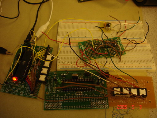
Some board we used: customized PC board, wireless module and external solder board.
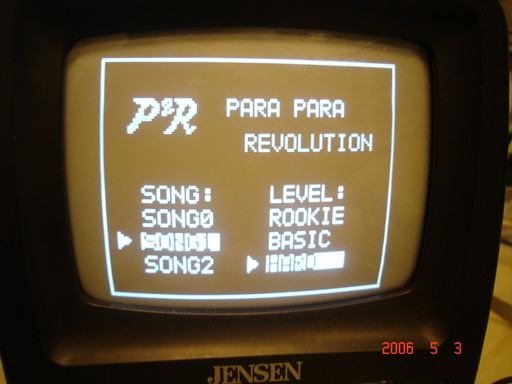
P2R starting screen
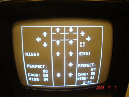
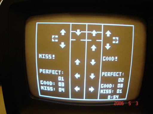
Playing mode. You can see the afterimage of the dynamic animation effect in the left picture.
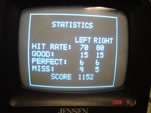
Final result.
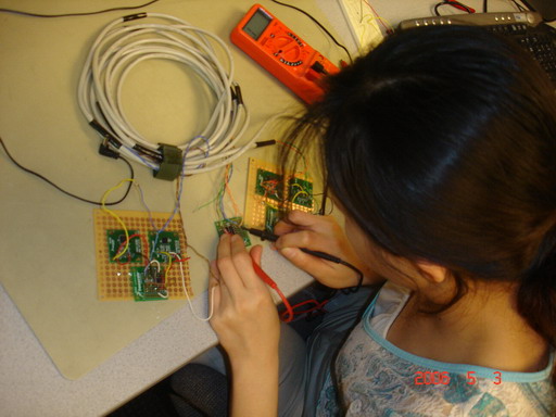
Chia-Hsuan was soldering the handset.
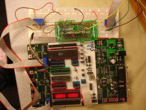
Wireless module (under construction)