Elevator Simulator
by Dylan Hughes and Andrew Costello
ECE 476
Introduction
The goal of our final project was to design an efficient elevator simulator that can accept input from a user and mechanically operate (on a small scale) a system of 4 floors and 3 elevators using pulleys and stepper motors. Users enter input using physical pushbuttons or the computer. This input is then processed by the MCU and orders are given to the elevators. We attempted to devise an algorithm that can optimally handle any number of floors. This project seemed like a fun challenge and something that had practical applications. Both of us have been frustrated at times by the inefficiency of some of the elevators here at Cornell, and we wanted to see if we could do a better job.

Definition of Terms
Inside Button – A button on the inside of an elevator car. A passenger would press this button after getting on an elevator.
Outside Button – A button outside the elevator cars. There are at most two outside buttons on each floor (up and down). In a real building there may be more for convenience, but the same functionality can be achieved with only two.
Request – A request to either get off on a floor (given to a specific elevator if an inside button has been pushed) or a request to be picked up on a floor going either up or down. An outside button push will only assign a pick-up request to a single elevator.
High-level Design
The essence of our project was the high-level design. Since it was our goal to simulate an efficient elevator system, designing the logic produce desirable results proved to be a challenge. We decided the best way to control three separate elevators was to have each elevator respond optimally to any given set of requests (to pick up or drop off passengers). We could then write an algorithm that would predict which elevator could respond the fastest to a passenger request and assign the request to that elevator. While our physical elevator system only consists of 4 floors, the design can be scaled to any number of floors.
Individual Elevator Behavior
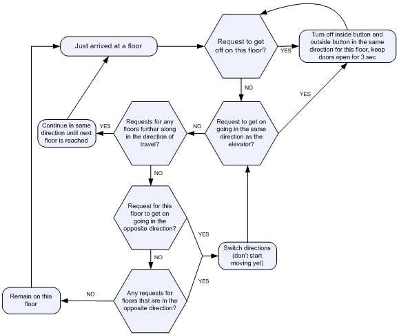
The basis for our elevator’s behavior is the elevator algorithm, in which the elevator handles all requests in one direction before turning around. Our code ensures that a single elevator will follow this behavior. The logic that controls a single elevator is shown below. Remember that in the case of outside buttons, a request is not necessarily the same as a button push (see definition of terms). Handling these buttons is covered in the next section.
Delegating Requests
In order to control our system of three elevators efficiently, we had to come up with a way to appropriately assign requests to each elevator. Assigning requests from the inside button pushes was trivial, as an elevator must respond to its own inside buttons. For each outside button pushed, only one elevator receives the request. Our algorithm to assign requests favors the elevator with the fewest other requests in order to split traffic evenly among the elevators and minimize time spent waiting to get off. In the case where two or more elevators have the same number of other requests, we compute the worst-case distance that each one must travel to answer the request. The three scenarios are explained below.
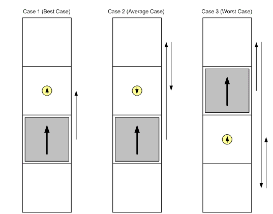
Case 1: In this case, the elevator is traveling towards the floor that the request is on in the same direction that the request is in. The worst-case distance (maximum number of floors) between the elevator and the request is just:
|requestFloor – currentFloor|
Where requestFloor is the floor that the request is on and currentFloor is the floor that the elevator is currently on.
Case 2: In this case, the elevator is traveling in the opposite direction that the request is in. The worst-case distance between the elevator is the distance from the elevator to end of the shaft in its current direction of travel plus the distance from the end of the shaft back to the request floor. So, if the elevator is traveling upward, the distance is:
(floors-1-currentFloor)+(floors-1-requestFloor)
If the elevator is traveling downward, the distance is:
currentFloor + requestFloor
Where floors is the number of floors in the elevator system.
Case 3: In this case, the elevator is traveling away from the floor in the same direction that the request is in. The worst-case distance is:
2*(floors – 1) – |requestFloor – currentFloor|.
Alternate Modes of Operation
We included several other modes of operation aside from the normal mode described above. Below is a quick description of each mode.
Trivial Mode – Sends elevator 1 to do everything, ignores other elevators.
Simple Mode – All the elevators chase each outside button press and respond to their own inside button presses. This is equivalent to having 3 separate elevators in trivial mode.
Sabbath Mode – Elevators ignore any button pushes. They move up and down stopping at all floors along the way. The elevators are staggered to minimize worst case waiting time.
Hardware Design
We built a 3-shaft, 4-story elevator model consisting of K’NEX and wooden dowels. We added motors and pulleys to raise and lower the elevators. The elevators are controlled using eighteen pushbuttons, twelve of which represent internal elevator buttons. The other six outside buttons call elevators to particular floors.
Mechanical Design
Our elevator shafts are built from plastic K’NEX pieces. We chose this material because it offered flexibility in design, ease of construction, and was available for free. We added wooden guide dowels to align the elevator cars within the shafts. The elevators are raised and lowered with twine using a pulley system. The other end of the twine was attached to pulleys on each motor. The motors were nailed to two parallel pieces of wood.
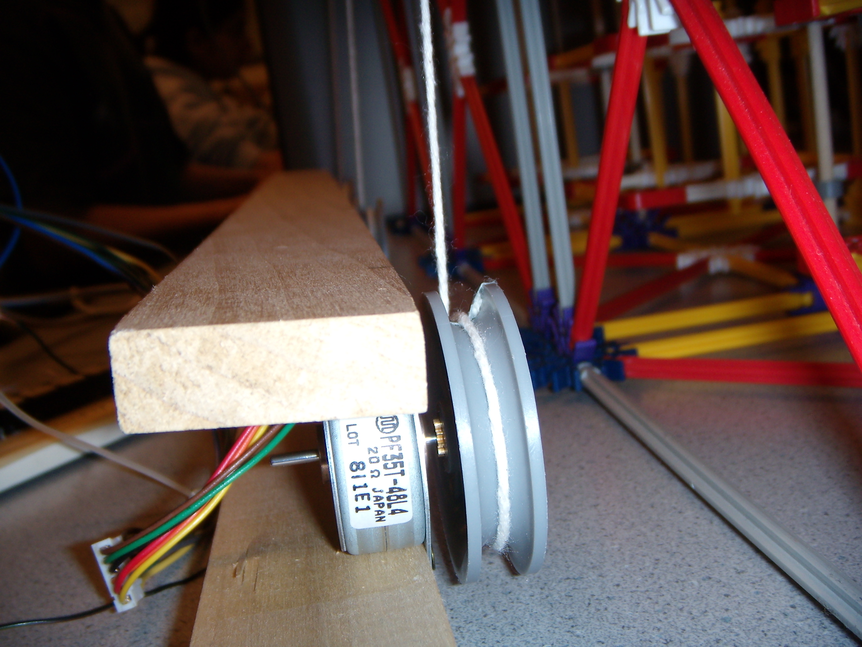
Electrical Design
We used three PF35T-48L4 stepper motors; one for each elevator. The motors were logically controlled by the MCU but were powered using a standard 12V lab power supply. Because the microcontroller cannot source enough current to run the motors, we added three ULN2003AN Darlington arrays, also attached to the power supply. Below is the circuit used to connect the MCU port to the stepper motor using the Darlington array.
The stepper motors use a 4-state configuration. Depending on the order of transitions between states, the motors either turn clockwise or counterclockwise. Each state consists of a two-hot pin assignment. Our program kept track of these states at alternated between them. This is explained further in the software section.
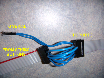
Of our eighteen pushbuttons, six are on the STK500. These 6 buttons are connected to pins 2 through 7 on port D of the MCU. Because we also need pins D.0 and D.1 for the RS 232 serial connection, we needed to make an adapter that allowed both the STK500 pushbuttons and the RS 232 jumper to be connected to port D. A picture of this adapter is shown below.
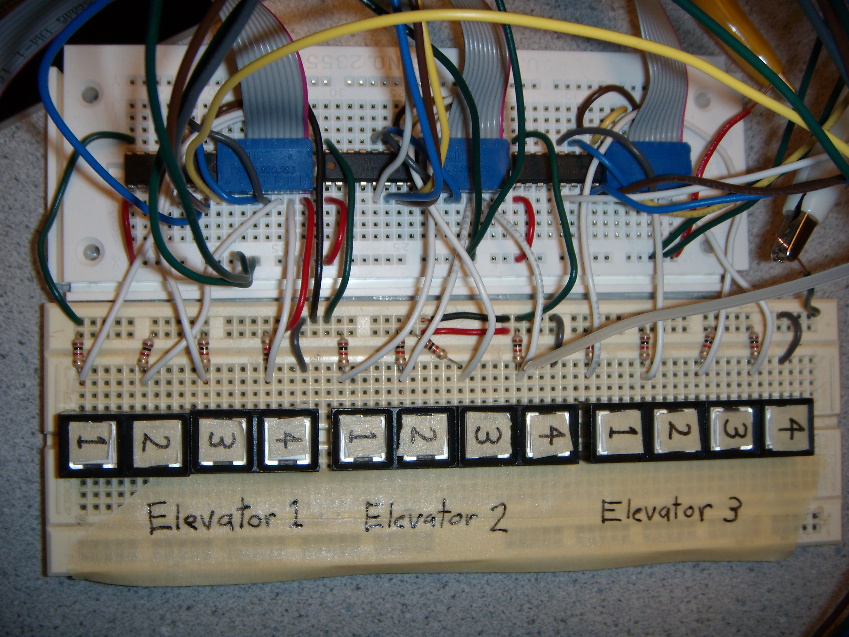
The other twelve buttons are mounted on a whiteboard and connected to VCC through 1 kW pull-up resistors on one end and to ground on the other end. When the button is pushed down the port pin is driven low and the MCU detects a button push; otherwise it remains high. The schematic for one set of four buttons is shown below.
 _
_
Hardware Difficulties
We ran into two problems in hardware. The first issue we came across was that the power supply we were using could not source enough current to power all 3 stepper motors. The current was capped at 500 mA, while each stepper motor uses 350 mA. To fix this issue, we simply switched to a larger power supply that can source more current.
Our second problem is that the stepper motors get very hot after being turned on for a while. We did not find a solution to this problem, although it is not a major issue. After several uncomfortable encounters with the motors, we decided to nail them to wooden boards rather than hold them.
Software Design
There are two parts to our software: the C code, which controls the elevator system, processes input from the user, and sends data to MATLAB, and the MATLAB code, which provides visual feedback as well as a secondary user interface.
C Code
The bulk of our C code implements the logic that is explained in the high-level design section. To control each elevator, we use three structs (stored on the heap) of type Elevator with different fields such as the current direction, current floor, and any requests (inside and outside) assigned to the elevator. This allows us to keep track of the current state of an elevator and determine appropriate behavior using a series of if statements in the oneStep function. We also use these fields to calculate distances when assigning requests from outside buttons in the addRequests function.
When in normal operation, every pass through the main loop polls the pushbuttons, sends the button state through the serial connection to MATLAB (if buttons changed), delegates outside button requests, and calls the oneStep function. Additionally, there is a TIMER0 interrupt that fires every millisecond. This interrupt checks the serial port for data to output to MATLAB. It also moves each elevator motor one step (by toggling pins on ports A, B, and C) every 50 milliseconds if the elevator is supposed to move. The distance between floors is 38 motor steps, so by keeping track of how many steps have been taken the program knows where the elevator is.
Refer to the appendix for complete C code.
MATLAB Code
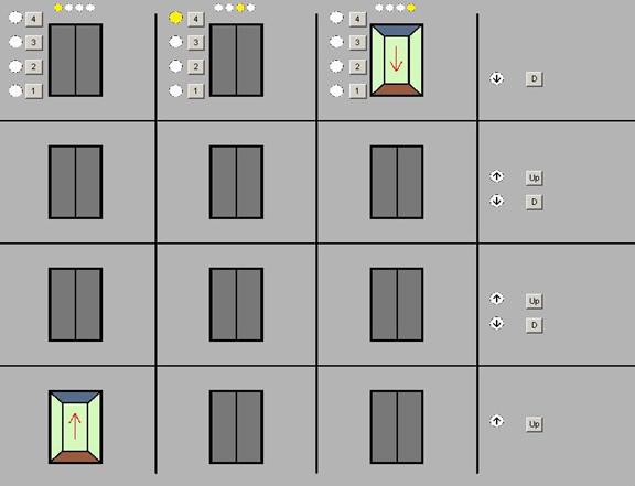
Our MATLAB program (elevator.m) constructs a GUI that communicates with the C program using the serial connection. We drew several elevator components in MS Paint (buttons, doors, etc.) The program places these images at appropriate locations to display the current state of the elevator system as a user would see it. This is accomplished by parsing strings sent from the C code.
The MATLAB program also allows users to simulate button presses using the computer rather than actual hardware. To do this, the input mode must first be set to computer in the C code. Using this option, a user can simulate an elevator system with more (or less) than 4 floors.
Additionally, our program keeps statistics on the average wait time for a passenger to get on an elevator and off an elevator. This is accomplished by timing how long a button remains on once pressed.
Refer to the appendix for the MATLAB code.
Software Difficulties
Our original algorithm did not appropriately separate single elevator operation from distributing requests among multiple elevators. This made it very difficult to write correct code. After adding several dozen hacks to deal with corner cases, we realized that our program was not scalable to multiple elevators. We were forced to rewrite the code in a more modular fashion.
Scaling the MATLAB code an arbitrary number of floors required much trial and error to get the image placement correct. Also, image placement used a different coordinate system from the MATLAB pushbuttons, complicating matters further. To retrieve data from the serial port we originally used fgets, which is a blocking function. This made the computer sluggish until we discovered the bytesavailable field of MATLAB serial objects, allowing us to poll for data before calling fgets.
Results
Performance and Accuracy
The best way for us to measure the results of our design is to put the elevator system in every conceivable situation and make sure it responds in the appropriate manner. For every test case, our elevator demonstrated logical behavior. Using our MATLAB GUI made testing much easier. Additionally, we are able to measure performance using the statistics kept by the MATLAB code. All of these statistics are reasonable and match our expectations, so we can be fairly certain that they are correct.
One interesting result is that Sabbath mode occasionally outperforms the normal mode of operation for a small number of floors. However, increasing the number of floors in our simulation makes the wait time for Sabbath mode much worse.
Safety Considerations
Our elevator simulator is extremely safe. There are no exposed sharp edges or high voltages that could injure a user. There are two protruding nails in between the pieces of wood used to mount the motors. Also, the motors run very hot to the touch.
Usability
Our design is user-friendly. The interface simply consists of 18 physical pushbuttons (or MATLAB pushbuttons). Using the elevator only requires pushing the appropriate button, much like an actual elevator.
Conclusions
Expectations
We met or exceeded most of the expectations that we had at the beginning. We found ourselves continually adding new features to the project. The result is a very efficient elevator system. One area where we may have fallen a bit short is critical failure avoidance. For example, we don’t have multiple strings supporting an elevator car or a backup system in case power is lost. This is something that we could have improved on. Also, we had the idea to write a MATLAB script that could send a series of commands to the elevator without any user input. This would be useful for comparing algorithms across different usage patterns. Finally, there is always room to improve upon the elevator algorithm.
Intellectual Property Considerations
All hardware and software design is our own. We did not borrow any code or sample any hardware.
Standards
Because our elevator system is meant only as a model for optimal elevator behavior and is not intended for actual use, we could not find any standards that apply to our project. There are some safety standards that would be violated if our elevator were intended for passenger use, such as a lack of a backup system in the event of a power failure.
Ethical Considerations
We abided by all items listed in the IEEE Code of Ethics during our project design process. Several of these items, such as rejecting bribes and malicious action, were not specifically relevant to this project, but are rather guidelines that we always adhere to.
We made all of our decisions with welfare of the public and environment in mind. As mentioned earlier, our design is very safe and does not harm the environment in any way. Additionally, our elevator simulator is simple to use and it’s applications are well understood.
Throughout the design and testing process, we were open to suggestions from our peers and instructors. Also, we listened to each other’s ideas and made compromises whenever there was a difference of opinion. We helped other groups with issues they were having whenever possible.
Our elevator simulator does not discriminate based on race, religion, gender, age, or national origin. In fact, we implemented a Sabbath mode to allow observant Jews to ride the elevator on Shabbat while refraining from using any electric devices. However, the buttons that control our elevator are not marked with Braille, so it will be difficult for blind people to operate. In a real version of this elevator, however, it would be easy to add Braille.
Appendix
Schematics and Data Sheets
All schematics and links to data sheets can be found in their respective sections above.
Budget
| Item | Cost |
| 3 PF35T-48L4 stepper motors | $3.00 |
| 2 white boards | $12.00 |
| 1 STK500 w/ Atmel Mega32 | $15.00 |
| 3 ULN2003AN Darlington arrays | $1.92 |
| 1 2-pin flat jumper cable | $1.00 |
| 1 12 Volt Power Supply | $5.00 |
| 12 Pushbuttons | Free (in lab) |
| K’NEX | Free (already owned) |
| 2 Wooden Boards | $3.00 |
| 3 Wooden Dowels | $1.50 |
| Twine | Free (Scavenged) |
| Nails | Free (Scavenged) |
| Total | $42.42 |
Specific Tasks
Building Elevators – Shared
MATLAB Code – Andrew
C Code – Shared
Circuit Design – Dylan
Testing and Debugging – Shared
Code
Video
References
Consulting: Prof. Bruce Land, Eric Okawa
Datasheets: ULN2003AN