
Wall of Pong is a fast-moving, interactive, laser-based pong game playable on any flat surface.
"The Elevator Pitch"
Wall of Pong is a fast-moving, interactive, laser-based pong game playable on any flat surface.
The system uses a digitally controlled laser projection platform to draw a pong ball onto any flat surface. This allows for a large playing area that can be set up almost anywhere. Hand held paddles with embedded sensors are given to each player. The real life paddles increases the interactivity of the game and makes it an enjoyable and dynamic derivative of the original PONG arcade game.
This project was a five week design lab for ECE 476 at Cornell University. Video of the final demonstration is available in the Results section.
Adrian Wong (aw259)
Bhavin Rokad (bkr24)
High Level Design
Inspiration | Concept | Mathematics | Standards
Project Inspiration
The Wall of Pong is actually the successor to the project that we were originally designing for ECE 476. Our original objective was to design a laser tracking system built around a circular saccade (see “Laser-Based Finger Tracking System Suitable for MOEMS Integration” by S. Perrin, A. Cassinelli, and M. Ishikawa). We completed most of the project, but we were unable to design the necessary focusing optics. As a result, we decided to adapt our base platform to the Wall of Pong concept.
The Wall of Pong brings the arcade PONG game to the real world by projecting an image of the pong ball on any flat surface and allowing players to play the game with real paddles. The game also targets all three of our personal objectives for our ECE 476 final project: an interactive electromechanical system with fast operation. We wanted a project that involved interaction between the user and the system with very fast response times to user's actions to give a satisfying experience. We also wanted to stress a project with electromechanical components, as we wanted something tangible with our project instead of a project based entirely in software.
Overall Concept
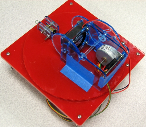
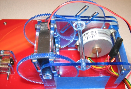
The laser projection platform viewed from behind.
The laser platform is built around three main components: the laser project platform, the hand held paddles, and the microcontroller. The first is the laser beam projection platform. The laser beam is first projected onto a rotating mirror. The reflected beam will be circular due to a slight off-axis mounting angle. The circular beam can then be steered using two motors. One motor controls the x-axis motion and the second motor controls the y-axis motion. The mechanical mechanism that allows for orthogonal rotation of the mirror in independent axes is called a gimbal.
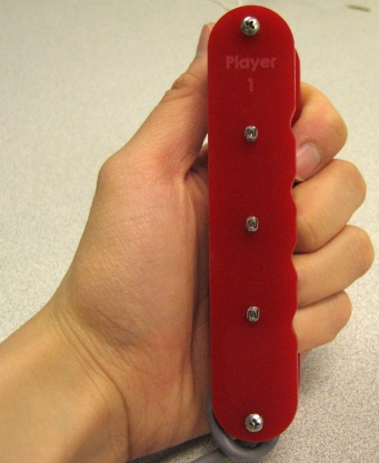
One of the player's paddles.
The second component is the hand held paddles. Each player will hold a paddle that has three embedded light sensors. The light sensors can detect when the laser beam hits the paddle. The light sensors are spaced close enough together so that they can collectively detect any ball collision along the full length of the paddle. The paddles are wired into the microcontroller through a long flexible cable.
The third component is the microcontroller itself. The microcontroller will control the operation of the gimbal to move the ball around the playing field and have it bounce off virtual walls. The microcontroller also handles the detection of the projected laser beam by two hand held paddles.
Background Mathematics
The pong ball is drawn using a gimbaled laser platform and two paddles are wired to detect the pong ball projection. Our two primary concerns were the angular resolution of our system as well as the operating speed of the laser pong ball.
Angular Resolution
Our target specification was to have an angular resolution of less than 0.3 degrees for targeting of the laser beam. This corresponds to 5.236 mm of spatial resolution at 1 meter range. We overdesigned the system with a 100% margin by designing for 0.15 degrees of spatial resolution in both axes. This means that our final design can place the laser beam with 2.6 mm of accuracy in both x and y axes at 1 meter range.
With each degree of mirror rotation, the projected beam actually moves twice as much. This can easily be seen by considering the law of reflection (angle of incidence is equal to angle of reflection). If the incident beam is held steady and the mirror is rotated by an angle θ, the incident angle as measured off the normal of the mirror has increased by θ and the reflection angle has increased by θ as well. The angle between the incident beam and the reflected beam has now increased by 2θ. This means that the target resolution must be 0.075 degrees per step for the motor mounted to the mirror.
The stepper motors only have a 7.5 degree step resolution. In order to increase this to 0.075 degrees per step to reach the target specification, the stepper motor must have a 100 fold increase in resolution. This is achieved through a combination of software and hardware. The software can double the resolution by half stepping the stepper motors. The remainder must be achieved through hardware.
One approach is to design a gear train for the stepper motor, which can increase the angular resolution as well as the torque output of the motor. The gear train must have a 50:1 gear reduction. The brass gear on the stepper motor has 10 teeth at 48 diametral pitch. A naive approach would involve a 500 tooth gear meshed to the 10 tooth pinion gear. That approach, however, would create 10.5” diameter gear. This is much too large for the mechanical gimbal design. Instead, our proposed compound gear train runs uses two 100 teeth gears and an intermediary 20 tooth gear (10:100 and 20:100). This achieves the 50:1 gear reduction target.
For the x-axis rotation, we can circumvent the loss of mirror resolution due to reflection by mounting the laser onto the same platform as the mirror. Since the laser moves along with the mirror, we simply rotate the entire assembly. This reduces our requirement to 0.15 degrees or a 50:1 gear reduction. We can again apply the half stepping approach to relax the hardware requirement to a 25:1 gear reduction. The y-axis gimbal assembly can fit on a 6.25” diameter gear, which corresponds to a 300 tooth gear at 48 pitch. If this gear is meshed directly to the 10 tooth pinion gear, this exceeds our target specification by creating a 30:1 gear reduction.
Operating Speed
With such a large gear reduction, the actual movement of the laser beam is also reduced by a factor of 50. We were concerned that the stepper motors would not be able to step quickly enough to move the ball in a satisfying manner for the game.
Our goal was for the ball to move at least 10 cm per second at 1 meter range. This corresponds to 5.71 degrees per second of angular velocity. Going through the 50:1 gear reduction, the stepper motor must reach 285 degrees per second. This corresponds to a frequency of 4.974 Hz in full step operation or 9.948 Hz at half step operation. This is readily achievable using a 16 MHz microcontroller.
Standards and Trademarks
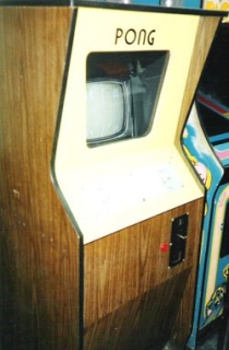
The original PONG arcade game. (Photo credit: ProhibitOnions)
Our system utilized a readily available, unaltered, laser pointer compliant with class IIIa laser power and safety specifications. In the United States, OHSA standards govern laser safety and personal protective equipment (PPE).
Additionally, the IEC 825 standard defines the maximum exposure limits of lasers and LEDs. The ANSI Z136-1 standard addresses the engineering and procedural controls necessary when using class IIIa lasers. Compliance with these safety standards is crucial for the safe and successful development of the laser game and therefore were followed closely.
The mechanical model design in Solidworks used ANSI standards.
PONG is trademarked by Hasbro Interactive. However, the context of our project is unlikely to cause any confusion between Hasbro's intellectual property and our own. Specifically, our project is presented within the context of a senior year microcontroller course, and the title Wall of Pong will not be used in any commercial derivations. Also, it is unlikely that one would confuse the laser projected pong system with the arcade game to the right.
Implementation
Software | Electrical | Mechanical
Software Details
Our final program is a reduced version of what we had written for our laser tracking system project. We removed all the features not necessary in the Wall of Pong (such as the digital phase locked loop), and we kept the core framework (such as the stepper motor functions). The main operation sequence will be described; specific details on stepper motor actuation, ADC control, and serial communication are described in separate sections below.
Main Operation Sequence
The program starts by initializing all ports, timers, USARTs, and application variables in the initialize function. After initialization, the program runs through the calibration sequence which sets the boundary of the playing field. The calibration function is a five state FSM that transitions whenever a paddle registers a hit. The first four states store the left, right, up, and down borders of the playing region by recording the coordinate of the ball when the paddle hit occurred. There is also a centering function that returns the ball to the center of the field. The center point is recalculated once the boundaries of the field are defined.
Once calibration has been completed, the game begins by calling start_game, which sends the ball moving in a random direction from the center. While running the main control loop, the program checks for paddle hits and boundary collisions. If the program detects a collision with a paddle or an upper or lower boundary, the ball reverses direction on that axis. However, if the program detects a collision with the left or right boundaries, the player on that side is designated as the loser.
Stepper Motors
The two stepper motors are actuated by the Timer 2 Compare Match ISR. The motors are controlled by energizing the motor windings in a specific sequence. The sequence is stored in an array titled full_step. There is also an alternative stepping sequence known as half stepping that energizes two sets of windings simultaneously. This effectively reduces the step size in half and doubles the resolution of the stepper motor. This sequence is stored in an array titled half_step. On each interrupt, the step indices for the x-axis and y-axis are incremented, decremented, or unchanged depending on the current ball direction. The x and y coordinates the ball are also adjusted appropriately. The output on port C to the ULN2003AN Darlington array is generated by looking up the correct step for each motor and combining the x-axis and y-axis outputs into the upper and lower nibbles of port C.
Timer 2 was configured to run at 15.625 kHz by prescaling the system clock by 1024. The speed of the stepper motors can be varied by adjusting the compare match value. At the full value of 255, the ISR will be called every 16.32 milliseconds. The lower bound on this is a compare match value of 28, which will call the ISR every 1.79 milliseconds. The maximum rated slew pulse rate of the motor is 560 pulses per second (1.78 milliseconds).
Light Detection and ADC
The three photocells in each paddle are part of a voltage divider whose output voltage is fed into six pins of port A. These voltages are multiplexed into the onboard analog to digital converter and stored as a 10-bit value. Only the top eight bits of the ten bit reading is used, since we are looking for large deviations around the threshold. The ADC is configured to run at 125 kHz in free running mode.
The function sample_paddles cycles through the three photocells on each paddle in turn and also initiates the conversion for each sample. The function only looks at the paddle in the direction where the ball is headed (left paddle for a left moving ball and vice versa). When the ball is not moving in the x-axis, the function will look at all six sensors across both player paddles. If the voltage level drops below a threshold, the program defines that as a paddle hit. Each photocell is individually addressable, so the program can also differentiate between whether the ball struck at the top, middle, or bottom of the paddle.
Remote Control and Debugging
A serial interface was added to allow remote actuation of the gimbal mechanism and also to display useful messages for debugging. The USART is configured to run at 9600 baud, no parity, one stop bit, and no flow control. The remote_control function interprets keypresses (WSAD) and moves the gimbal in the commanded direction. The adc_readout function displays the raw ADC values for each photocell to verify operation of the electrical circuit.
Electrical Details
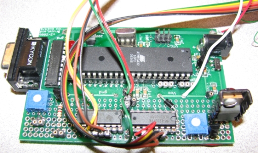
The ECE 476 prototyping board with ULN2003A stepper motor drivers and a TIP31A BJT regulator.
Power Management
The TIP31A regulator circuit.
The power supply for the ECE 476 custom PCB board is 12 Volts DC. A LM340T5 voltage regulator on the custom board produces a 5 Volt DC level for the MCU, brushless DC motor, and laser. However, the gimbal's stepper motors require a 7 Volt supply. This level was created using a darlington-based regulator consisting of a 2N3904 NPN BJT and a TIP31A NPN BJT. A 10kΩ potentiometer at the base of the 2N3904 BJT allows for the output voltage to be easily varied.
The TIP31A BJT can sustain up to a 3 Amp collector current ensuring our stepper motors were not current limited in the event we wanted to run the steppers at a faster speed or high voltage. Presently, the external limit of the stepper motor 's current arised from the use of at 12 Volt power supply with a 1 Amp rating.
Stepper Motors
Stepper motor windings.
Each unipolar stepper motor is controlled via two three-pin connectors and driven using the ULN2003AN high-voltage high-current Darlington array. A stepper motor turns when its leads (attached to electromagnets) are sequentially energized in an alternating pattern to turn the rotor (Stepper Motor Animation). The exact pattern is described in the Software Design subsection. The center-taps of each winding is connected to the 7 Volt supply provided by the power management circuit.
Brushless DC Motor
The brushless DC motor took the form of a simple computer fan running at 5 rather than 12 Volts. The lower voltage allowed for the mounted mirror to create a smoother, more circular, pong ball shape.
Electronic Laser Control
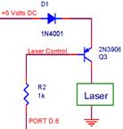
Laser control circuit.
Our 635nm red laser was initially powered by three button batteries totaling 4.5 Volts, however,through testing we determined that the laser would reliably operate at 4.3 Volts. This implied that we could use a diode to drop V_cc to a level suitable for the laser. (Although 5V probably could have been used to power the laser, we did not want to risk permanently damaging the laser and its supporting circuitry.) We used a 1N4001 diode to obtain this voltage drop.
The laser itself was controlled using a PNP BJT (2N3906) by connecting the BJT's collector terminal to the laser's Vcc. A low voltage would turn the laser on and a resistor was required between the MCU and the BJT's base because BJT's are current based devices.
Player Paddles
Paddle resistor divider circuit.
We were able to reliably detect the laser pong ball using a PDV9006ND cadmium-sulfide photo cell. The laser pong ball's diameter at a distance of 1-2 meters was sufficiently large for three of these sensors per paddle, each separated by 2 inches, to detect the laser pong ball regardless of where the ball crossed the paddle.
Since the CdS photodetectors are actually photo-resistors we setup a voltage divider to create a voltage we could sample using the ADC. This voltage divider is governed by V_ADC=R_sensor/(R_bias+R_sensor ) V_cc with R_sensor varying from 16kΩ in ambient lighting conditions to approximately 1kΩ when detecting the laser. This difference allowed for a threshold to be used to detect the presence of the laser. A R_bias of 10kΩ was chosen because it lay approximately between these two values. The output voltage of this circuit, a six-bit V_ADC, was sampled and processed with the Atmel Mega32's onboard ADC.
Mechanical Details
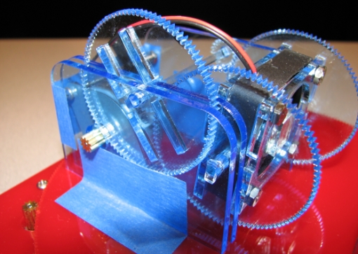
The pong ball is drawn using a spinning mirror and a gimbal mechanism with three degrees of freedom. The laser beam is targeted at the center of a mirror mounted on a brushless DC fan. The mirror is mounted slightly off-axis, which causes a circular beam reflection when the mirror starts spinning. The fan is mounted on a gear to allow it to pivot up and down. This allows for one rotational degree of freedom in the phi-axis that translates to y-axis motion of the pong ball.
Close up of the acrylic gear train.
The gear is at the end of a 50:1 gear train. This changes the 7.5 degrees per step (3.25 degrees for half stepping) into 0.15 degrees per step (0.07 degrees for half stepping). The gear train is made out of 48 pitch gears to match the 10 tooth brass gear mounted to the PF35T-48L4 stepper motor. This stepper motor is designated the y-axis motor.
Close up of both x-axis and y-axis assemblies.
The entire gear train assembly sits on a large 300 tooth gear that connects directly to another PF35T-48L4 stepper motor. This results in a 30:1 gear train that moves at 0.25 degrees per step (0.11 degrees for half step). This allows for the second rotational degree of freedom in the theta-axis that translates to x-axis motion of the pong ball. The stepper motor designated as the x-axis motor is mounted to an acrylic base that also holds the center axle for the 300 tooth gear. Lastly, a laser is also mounted on the 300 tooth gear and is configured to point directly into the center of the mirror.
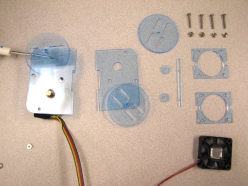
Parts cut from 3mm acrylic sheet.
The gimbal mechanism was designed entirely in Solidworks and fabricated out of 3 mm and 6 mm acrylic sheets. The design was cut on an Epilog laser cutter in just under 3 minutes. The flat parts were then assembled into the free standing structure without any application of adhesives. A small piece of tape was applied to prevent people from accidently dismantling the structure when inspecting it.
Results

This video was taken from our end of semester demonstration. Now with AUDIO!

This video was also taken from our end of semester demonstration. No audio on this one and at slightly lower quality.
Our final design performed quite admirably, creating an enjoyable and impressive laser-based pong game. In doing so, the project met the criteria we set at the start of the course: an exciting, fast-moving, interactive electromechanical system with a high level of usability. Mechanical stability and therefore the laser's accuracy was retained during the design and creation process by accounting for the laser cutter's kerf by over-sizing and under-sizing elements by 0.19 mm. Electrical and software components such as sampling the paddles and moving the gimbal performed correctly and reliably.
Our laser posed our project's primary safety hazard. Low power Class IIIa laser diodes such as those used in our design and found in laser pointers do not normally produce injury if viewed only momentarily with the unaided eye. It is important to not use this as a general rule to become compliant with laser safety since class IIIa lasers are not unconditionally safe. Players are advised not to look into the laser beam, but only at the pong ball reflection.
In the creation, testing, and use of our project we ensured our laser's maximum permissible exposure (MPE) was taken into account. Our laser carried a Danger label indicating its power output could exceed 2.5 mW/cm2, and therefore its MPE was sufficiently low that the human aversion time for a bright light should not be used as a basis for safety when dealing with the laser. This safety level implies that while the reflections off the wall when playing our game are not hazardous, one should avoid at all cost to look directly into the laser's outgoing beam.
During our lab session's safety was enforced by ensuring the laser remained off at all times except when it was being used. Further we ensured other persons in the lab were not accidently exposed to our laser by shining our laser pong ball at a box or a neighboring wall. Despite our final project involving a larger laser pong ball, we tested at short distances to avoid accidental exposure. Additionally we ensured the laser standards such as OSHA's and IEC 825 which defines the maximum exposure limits of lasers were followed.
The secondary safety hazard we considered was the laser cutter which we used to cut the acrylic pieces in our mechanical design. When using the high power laser cutter we ensured we wore safety goggles, safety locks were in place, and we did not stare at the sparks occasionally generated during cutting.
Our system incorporates a high degree of usability. The compact and rugged design makes it ready for use by the public. After quick instructions, many fellow students were able to be start playing and enjoy the game.
Conclusion
Our results exceeded our expectations: game-play was highly interactive; the mechanical assembly accurately and reliably moved the laser pong ball; the photo sensor reliably detected the laser's presence.
Next time, we would have liked to make some of the slots on the mechanical platform slightly smaller to obtain a tighter fit between the x-axis and y-axis assemblies. We would also like to include sound effects. The capability to individually address each photosensor went unused. Future refinement could use that information to skew the reflection of the ball or change the ball speed.
Future students interested in pursuing a similar project may find the Pololu laser cutting service useful. Our laser cut parts were made using the same type of machine.
Ethical and Legal Considerations
We closely followed IEEE Code of Ethics throughout our project. Specifically we ensured that safety precautions were considered and followed throughout our final project. In the rush of final projects it is easy to lapse on safety precautions as well as courtesy and respect for fellow classmates, their projects, and the lab. We always made sure to keep the laser targeted away from other students. We ensured that we were fair to everyone we interacted with and gave credit to the contributions and resources provided of others. Although discussions and criticisms over the design within our group grew heated at times, the end effect was an improved understanding of alternatives and in depth understanding. Additionally, we were realistic when we realized that we might not be able to pursue our original project idea. This involved accurately portraying our current status and problems to our TAs and professor. Despite being asked about our project many, many times over the last five weeks, we took the time to explain our project in depth in a manner that increased the understand of technology.
We do not have any legal considerations since we did not use code from other sources and did not use parts regulated by agencies such as the FCC. As mentioned before, the name Wall of Pong is unlikely to be confused with the true PONG game by Hasbro.
Appendix
Schematic
Full schematics are available in PDF format.
Download the circuit schematic.
Download the hardware schematic.
Budget
Our budget was not to exceed $50. Our true out of pocket expenses was actually just $1.00 (for the mirrors). All other parts on this list were found in the lab or scavenged. We also chose to list the price of the acrylic parts as the cost it would take to fabricate it through Pololu, even though we used our own laser cutter.
| Part | Quantity | Cost | Total | Source |
|---|---|---|---|---|
| -- | -- |
-- |
$48.66 |
-- |
| 10k PDIP Resistor Pack | 1 |
-- |
-- |
ECE 476 Digital Lab |
| RS-232 Serial Port | 1 |
$1.00 |
$1.00 |
ECE 476 Digital Lab |
| MAX233CPP | 1 |
-- |
-- |
Sampled |
| Red LED | 1 |
-- |
-- |
ECE 476 Digital Lab |
| Jumpers | 3 |
-- |
-- |
ECE 476 Digital Lab |
| 16 MHz Crystal Oscillator | 1 |
-- |
-- |
ECE 476 Digital Lab |
| LM340T5 Voltage Regulator | 1 |
$0.42 |
$0.42 |
ECE 476 Digital Lab |
| Slide Switch | 1 |
-- |
-- |
ECE 476 Digital Lab |
| TIP31A NPN BJT Transistor | 1 |
-- |
-- |
ECE 476 Digital Lab |
| 2N3904 NPN BJT Transistor | 1 |
-- |
-- |
ECE 476 Digital Lab |
| 2N3906 PNP BJT Transistor | 1 |
-- |
-- |
ECE 476 Digital Lab |
| 1N4001 Diode | 1 |
-- |
-- |
ECE 476 Digital Lab |
| 10k Trimpot | 2 |
-- |
-- |
ECE 476 Digital Lab |
| ULN2003AN Darlington Array | 2 |
$1.00 |
$2.00 |
ECE 476 Digital Lab |
| Atmel ATMega32 | 1 |
$8.00 |
$8.00 |
ECE 476 Digital Lab |
| 8 pin DIP Socket | 2 |
$0.50 |
$1.00 |
ECE 476 Digital Lab |
| 40 pin DIP Socket | 1 |
$0.50 |
$0.50 |
ECE 476 Digital Lab |
| Laser Diode | 1 |
-- |
-- |
Previously Owned |
| PF35T-48L4 Stepper Motor | 2 |
$1.00 |
$2.00 |
ECE 476 Digital Lab |
| Brushless DC fan | 1 |
$1.00 |
$1.00 |
ECE 476 Digital Lab |
| Acrylic Sheet | 2 |
$4.00 |
$8.00 |
Equivalent |
| Cutting Time | 3 |
$2.50 |
$7.50 |
Equivalent |
| PDV9006ND CaS Photocells | 6 |
$1.04 |
$6.24 |
Digikey |
| 12V Power supply | 1 |
$5.00 |
$5.00 |
ECE 476 Digital Lab |
| Custom PC Board | 1 |
$5.00 |
$5.00 |
ECE 476 Digital Lab |
| Small solder board | 1 |
$1.00 |
$1.00 |
ECE 476 Digital Lab |
| Mirrors | 1 |
$1.00 |
$1.00 |
Lowes |
Tasks
Adrian Wong designed the Solidworks CAD model of the gimbal and paddles and fabricated the laser projector parts. He also wrote the stepper motor and ADC code on the microcontroller.
Bhavin Rokad designed the power regulator and stepper motor driving circuits. He also soldered the prototype board and prepared the electrical schematics in Allegro Design Entry CIS.
The game code was jointly developed and assembly of the platform was also done jointly. The report was divided into sections with each team member writing about the portion with which they were most familiar. Adrian Wong wrote the introduction, software details, mechancial details, and most of the high level design. Bhavin Rokad wrote the electrical details, results, conclusion, and the standards section in high level design.
The website was formatted to Cornell University Visual Identity guidelines by Adrian Wong.
References and Acknowledgements
We did not use any code from other sources other than our prior labs. We would like to reference a past ECE 476 project (Loucetios Lighting control system by Eric Okawa, Marcelo Garza, and Abhijeet Agarwal) for the stepper motor implementation. It was useful as a reference implementation that allowed us to get started rapidly.
The inspiration for the laser tracking platform is from Smart Laser Scanner for Human-Computer Interace, although our design of the laser projection system was original. The idea of creating a PONG game was borne out of a desparate last ditch effort (four days before the due date) to salvage the remnants of the laser tracking project into a viable ECE 476 demonstration.
Thank you to Bruce Land for his assistance and providing the supplies in the lab. Thank you to our TAs who kept the lab open in the wee hours of the night and their invaluable advice. Thank you also to the Cornell Computational Synthesis Lab for the use of their laser cutter.
Datasheets
- 2N3904 - NPN BJT
- 2N3906 - PNP BJT
- TIP31A - NPN BJT
- ULN2003AN - Darlington Array
- LM340T5 - 5V regulator
- MAX233CP - Serial port communication
- PF35T-48L4 - Stepper motors
- ATmega32 - Atmel microcontroller
Code Listing
The system clock is set to 16 MHz with no fuse bits. The microcontroller is loaded on an ECE 476 prototype board. Further information can be found in the ATmega32 datasheet.
