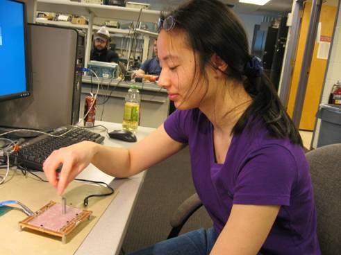
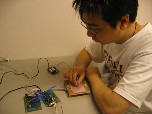
Abby Drawing and Yiyin Scratching his Head
May 2007ECE 476
Yiyin Ma(ym82) and Abby Lin(ayl26)

| Part Name | Number | Total Price | Source |
|---|---|---|---|
| D42-N50 Magnets | 10 | $3.20 | KJ Magnetics |
| Atmel Mega 32 | 2 | $16.00 | Bruce Land |
| MP 120 (12 Hz Crystal) | 1 | $0.94 | DigiKey |
| 9V Battery | 1 | $2.00 | Local Grocery Store |
| Custom PC Board | 2 | $10.00 | Bruce Land |
| Solder Board | 1 | $2.50 | Bruce Land |
| Power Supply | 1 | $5.00 | Bruce Land |
| RS232 Connector | 1 | $1.00 | Bruce Land |
| FreeScale Board | 1 | Sampled | FreeScale |
| 9 volt battery clip with 3 and 5 volt regulators | 1 | Sampled | FreeScale |
| MAX232 | 1 | Sampled | Maxim |
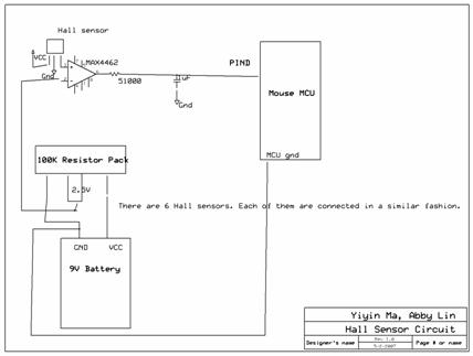
| A1302EU-AT (Linear Hall Sensor) | 6 | Sampled | Allegro |
| Max4462 (Diff Amps) | 6 | Sampled | Maxim |
| Pushbuttons | 3 | Already Owned | Yiyin Ma |
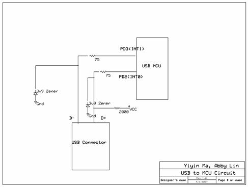
| USB Cable | 1 | Already Owned | Yiyin Ma |
| Plastic CD Case and Foam | 1 | Already Owned | Yiyin Ma |
| Total: | $40.64 |
| Task Name | Person |
|---|---|
| Sampling and ordering/buying parts | Shared |
| USB code modification | Abby |
| Mouse Component Code | Shared |
| Code testing | Shared | Soldering | Yiyin |
| Webpage | Abby |
| Research | Shared |