
- Introduction
- About Us
- Abstract
- Introduction
- Design
- High-Level
- Hardware
- Software
- Conclusion
- Results
- Testing & Use
- Ethics, Legal, & IP
- Appendices
- USB Overview
- Code Listing
- Schematics
- Parts List
- Responsibilities
- Reference
- License
About Us
We are three Juniors in Cornell University's College of Engineering. Ben "For Some Reason I Like Medicine-Tasting Energy Drinks Now" Hutton and Devrin "The Assembler" Talen are Electrical and Computer Engineering majors. Chris "Interrupt-less" Leary is an ECE and Computer Science double major.
Abstract
The prominence of microcontroller-based embedded design and a steadily increasing base of USB peripherals provided the impetus for this project. Previous implementations of USB software solutions have seen a great deal of success on more powerful microcontrollers[1], and it was hypothesized that a scaled down version of such an implementation would be possible using Atmel's 8-bit ISA. A fully functional Low Speed USB Host Controller was created for the Atmel Mega32 according to ANSI C99, with the exception of the carefully assembled Serial Interface Engine, which was written in Atmel's 8-bit assembly language. From this code base, USB communication was established, and an (ANSI C99) API was created for peripheral utilization. These results demonstrate the propensity for any Low Speed device's nearly seamless use in the AVR programming environment. This project was also notably successful in achieving goals of hardware simplicity, unobtrusiveness when used as a software library, complete originality of code, and utilization and production of solely open source software.
1. Jungo Software extended its USB software stack implementation to include Atmel's ARM7 and ARM9 microcontrollers, which use a 32-bit ISA. This implementation runs at Full Speed (12Mb/s).
Introduction
A software implemented USB 2.0 Host Controller was created for the Atmel Mega32 microcontroller.
This project has yielded a library that can be included from any program written for the Mega32. By using this library, a user can implement USB functionality with their application with minimal fuss. Several compiler options are included for various levels of debugging and verbosity.
Documentation supplied by the USB Implementers Forum's website and various summary articles allowed for the development and implementation of the USB protocol stack for the Atmel Mega32. We broke down the protocal into layers of abstraction, implementing one on top of the other. We designed the software such that any layer (coupled with those beneath it) is able to handle USB communication.
High-Level Design
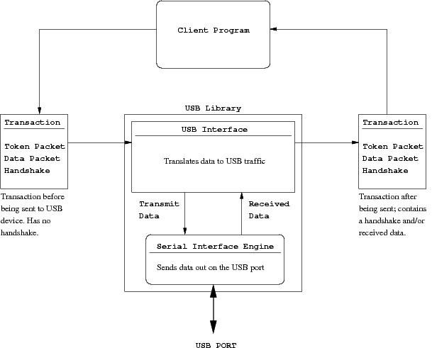
The goal of our project was to create a software library for any Atmel AVR series microprocessor. The software library is implemented as an interface to a USB port that accepts "transactions." These transactions are passed to the USB Interface, which handles converting them to valid bus traffic. This traffic is then sent out via the Serial Interface Engine (SIE). The SIE also handles reading traffic back from a device, and reports this to the Interface. The Interface modifies the transaction passed to it, and this is returned back to the client program. In this manner, our library abstracts the process of sending and receiving USB data.
Hardware Design
We built a Low Speed USB Transceiver according to USB spec. We used an Atmel Mega32 microcontroller plugged into an STK500 development board. Using our program, one of the ports on the Mega32 is dedicated to USB functionality, and is hooked up to the transceiver. Of this port, 5 pins are used:
| Pin0 | Tx- |
| Pin1 | Tx+ |
| Pin2 | Output Enable |
| Pin6 | Rx- |
| Pin7 | Rx+ |
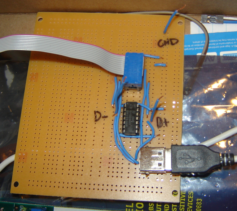
The goal of the transceiver hardware is to combine the Rx and Tx lines into one bi-directional set of lines: D+ and D-, which operate using differential encoding.
It is possible to connect the Rx pins directly to D+ and D- as they aren't trying to change the value on the lines - just read them. The Tx pins must be connected through SN74126N tri-state buffers so that they can be disconnected from D+ and D- when they aren't transmitting - otherwise they'll try to drive the line to their own values. The tri-state buffer essentially inserts an open circuit, and are controlled (active low) by an output enable pin - Pin2.
The USB spec requires both the D+ and D- lines be pulled to ground through 15 kOhm resistors right before they enter the USB cable. Also included in the cable are Vbus (5V) and Gnd lines, which are connected to the STK500's port's Vtg and Gnd pins, respectively.
Our hardware design is meant to be easily replicable in lab (following the wiring and block diagrams in the Schematics Appendix) - it is composed of parts acquired entirely from the lab, with the exception of the USB port - so that our code could be potentially used in future projects and or laboratory assignments.
Software Design
Driver Layer
The driver is the client program that uses the USB library. This is the layer that creates transactions to send to the USB Interface.
USB Interface (Host Controller)
The USB Interface is the bridge between the client program (driver) and the Serial Interface Engine (SIE). It is the Interface that turns the data expressed in the packets of a given transaction into USB traffic that the SIE can understand. In its operation, it accomplishes several large tasks:
First, the USB Interface manages transactions that are passed to it. To make using USB as seamless as possible, the interface will modify the transaction passed to it and return this to the client. This allows both the client and the interface to keep track of several transactions at a time. After the interface has used the SIE to communicate with the USB device, it will store the results of the transfer into the transaction that it was processing. This saves on memory usage, as only a minimum number of transactions need to be created to accomplish communication. This also gives rise to the way in which transactions are passed to the interface. The interface maintains a FIFO stack of pending transactions. New transactions are pushed onto the stack. When the client wants a given transaction to be run, it pops the oldest transaction off the bottom of the stack. This is useful for queueing a complicated series of transactions (such as receiving a device descriptor). The client creates the transactions beforehand, pushes them into the interface, then pops them off as it is ready to process them.
The second major design aspect of the USB Interface is that it communicates with the SIE and readies all data passed to it for USB traffic. This involves three major steps:
- Aligning all fields in the transmit buffer in LSB to MSB order, and decoding all data read by the SIE back into a readable format for the client. This is harder than it sounds, namely because the fields of the different packets (token, data, and handshake) are all different bit lengths, and not all multiples of 2. This makes packing data into the buffer, and reading data from the buffer after a transaction, a tricky task.
- Bit stuffing (and unstuffing) a transaction. USB 2.0 requires that when sending more than six 1's at a time on the bus, that there must be one 0 bit inserted. In other words, if the data to be sent has six or more 1's in a row, then a 0 must be inserted after every six. This is a consequence of the lack of a clock on the USB bus, which necessitates that devices maintain a phase-locked-loop (PLL) with the host controller. Because the data is NRZI encoded (discussed below), sending a string of 1's means that there will be no transition on the data line. This would cause the PLL to be broken, and inserting a 0 ensures that the line will toggle at a minimum rate.
- Data is sent on the line encoded as Non-Return-to-Zero-Inverted (NRZI). This encoding scheme operates by toggling the data line for each data 0 bit, and maintaining the line for each data 1 sent. This, like bit stuffing, is meant to keep a PLL between the host and the device. The USB Interface has to encode the data in the packets of the transaction in NRZI format. In addition, data received by the device must be decoded from NRZI.
Serial Interface Engine
The lowest level of software is the Serial Interface Engine (SIE). This level is implemented in assembly code due to timing constraints. Creating and maintaining a USB low-speed link requires being able to transmit and receive data at 1.5 Mb/s. By using a 15 MHz crystal (rather than the usual 16 MHz), the SIE achieves this by transmitting and receiving once every 10 cycles.
The SIE sends and receives transactions. A transaction is comprised of three packets: a token packet, a data packet, and a handshake packet. Depending on the type of transaction, these will be transmitted/received by either the USB host or the function (device). The SIE must make decisions on whether to transmit or receive the data in the space of a few cycles before it must react to data, or send it. Once the SIE has finished the transaction, it stores all the results back into a single location for the Host Controller to handle.
The SIE was broken up into macros that were units of functionality. Several parts of the SIE were similar, such as sending a sync field, or the process of sending bits of the token packet. To improve code readability and maintainability, we created macros to do these parts. This idea is recursed, and several macros use other macros within themselves. Overall, the SIE is a piece of tightly optimized assembly code that bit blasts buffers efficiently and receives (and stores) data quickly as well.
Results
Our USB Host Controller successfully established communication with a low-speed mouse. Our library is easy to include in any existing program, and requires minimal setup. Being USB, however, and implementing the full specifications for low-speed devices means that significant amounts of time can be spent processing the USB data, and the program must concede control to the USB framework when trying to communicate to a device. At other times, however, keeping USB communication active, however, requires no upkeep. This makes our USB library an ideal fit for any light- to middle-weight program on an AVR microprocessor that requires USB communication.
When we set out to do this project, we both foresaw the difficulty that implementing USB entailed as well as envisioned the potential utility of as USB Host Controller driver for the Atmel Mega32. Implementing the HC consumed all of our available time, and while we were able to get a USB mouse working as a demonstration, we did not have time to implement anything else. In addition to mice, USB keyboards could be easily made to work with the Mega32. Also, flash drives and card readers could be added to increase storage, to allow the Mega32 to operate on larger sets of data. To do this, some sort of storage driver (such as FAT32) would also need to be written.
We began a rather thorough code re-write a few days before the project was due that we were unable to complete on time. Were we to do this project over again, or to continue working on it, we would continue with the direction we had been going, implementing the Open Host Controller Interface. Also, one key hardware lesson we learned is to not rely on whiteboards for high-frequency signals - capacitance within the board made device response very flaky.
We set out to implement a subsection of a very large, very well-defined standard, from the onset knowing that we could never comprehensively implement it, yet attempting to remain faithful to its details. We fall short of USB2.0 in several significant ways. First, we only support low-speed devices, which restricts us to only Control and Interrupt transfers. Second, we only support one device at a time.
Safety was very easy to maintain within our design. We have very little actual hardware, so very little to risk injuring ourselves with. All currents and voltages are very low. We don't have an RF transmitter, so we won't interfere with other projects or devices. Our code is meant to be usable by other people, potentially others in this class, as a framework to utilize USB devices in Mega32 projects.
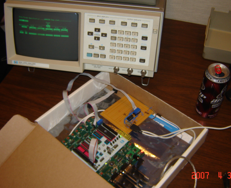
Hardware Design Stats
| Measured | Spec | |
| Pulse Width: | 660 ns | 666ns |
| D+ Rise Time: | 30 ns | 75ns-300ns |
| D+ Fall Time: | 18 ns | 75ns-300ns |
| D+ 1 Average Value: | 3.06 V | >2.8V |
| D+ 0 Average Value: | -0.031 V | <0.3V |
| D- Rise Time: | 40 ns | 75ns-300ns |
| D- Fall Time: | 26 ns | 75ns-300ns |
| D- 1 Average Value: | 3.15 V | >2.8V |
| D- 0 Average Value: | 0.125 V | <0.3V |
Testing and Use Cases
Testing
Incremental changes to software were run through regression testing, set up to ensure that previously working functionality did not break as new code was added. As the code was a protocol stack with layers of abstraction, each layer could be tested and verified independently.
Simple HID Mouse Driver
Getting a mouse to work with our USB driver is not difficult, and example code has been provided to demonstrate. A sequence of Standard Requests and resets must be issued to the mouse to get it into a state where it will begin giving output on its IN Endpoint 1.
- Reset the line
- Request the device descriptor using a from the default address (address 0, endpoint 0) GET_DESCRIPTOR request, and after receiving 8 bytes (one data payload), reset the line again
- Use SET_ADDRESS to set the address of the mouse to 1 (so now it responds to Control transfers at address 1, endpoint 0)
- Request the device descriptor again, using GET_DESCRIPTOR
- Request the first 9 bytes of the configuration descriptor, also using GET_DESCRIPTOR
- Use SET_CONFIGURATION to set the configuration of the mouse to 1 (so now it's active, behaving like a mouse, sending regular reports over its Interrupt pipe)
- Request the HID report descriptor using GET_REPORT
- Begin looping through IN Interrupts, sent to address 1, endpoint 1. The resulting data will be your mouse's click and incremental movement data
Ethical, Legal, and IP Considerations
IEEE Code Of Ethics
Reproduced below is the IEEE code of ethics, a document that serves to guide the ethical conduct and decision-making of electrical engineers during the course of their design and fabrication work. It thus serves as the ethical guideline by which projects in ECE476 are conducted.
We, the members of the IEEE, in recognition of the importance of our technologies in affecting the quality of life throughout the world, and in accepting a personal obligation to our profession, its members and the communities we serve, do hereby commit ourselves to the highest ethical and professional conduct and agree:
- to accept responsibility in making decisions consistent with the safety, health and welfare of the public, and to disclose promptly factors that might endanger the public or the environment
- to avoid real or perceived conflicts of interest whenever possible, and to disclose them to affected parties when they do exist
- to be honest and realistic in stating claims or estimates based on available data
- to reject bribery in all its forms
- to improve the understanding of technology, its appropriate application, and potential consequences
- to maintain and improve our technical competence and to undertake technological tasks for others only if qualified by training or experience, or after full disclosure of pertinent limitations
- to seek, accept, and offer honest criticism of technical work, to acknowledge and correct errors, and to credit properly the contributions of others
- to treat fairly all persons regardless of such factors as race, religion, gender, disability, age, or national origin
- to avoid injuring others, their property, reputation, or employment by false or malicious action
- to assist colleagues and co-workers in their professional development and to support them in following this code of ethics
Approved by the IEEE Board of Directors February 2006
Almost all of our project was in software. For what hardware fabrication was necessary, all specified precautions were taken. Specifically with regards to soldering, proper eye protection was worn at all times and irons were kept at reasonable temperatures.
There were no conflicts of interest present in our project, in any form. We are not beholden to any outside group or company in any way, nor did we encounter or deal with bribery. We did not encounter any situations where we noticed we were treating anyone unfairly, nor did we harm or injure anyone or anything by our actions.
This project was undertaken knowing that it would stretch our skills and abilities to their limits, forcing us to improve our technical compentence in the area of hardware/software interfacing, object-oriented c programming, assembly programming, protocol stack design and implementation, specification reading and comprehension, and project management. This project, though submitted for a grade and licensed for future use, was mainly undertaken for ourselves - we are the ones who benefit from the time and effort put into learning these things and improving our technical competencies in these areas. Working in a group of three, each of us having different strengths and specialties allowed us to learn from each other, assessing and critiquing each other's technical work and offering improvements.
All code is written by us with a very few exceptions where noted. As we were implementing a specification (USB2.0), a significant amount of our design came from its technical documentation.
IP Considerations
Almost all of our code (>99%) was written by us. We borrowed CRC5 code from http://www.lvr.com/files/usb_crc.c and adapted it, using instructions in www.usb.org/developers/whitepapers/crcdes.pdf.
The USB2.0 Specification is provided at http://www.usb.org/developers/docs/ with the following disclaimer:
THIS SPECIFICATION IS PROVIDED "AS IS" AND WITHOUT ANY WARRANTY OF ANY KIND, EXPRESSED OR IMPLIED. WITHOUT LIMITATION, THERE IS NO WARRANTY OF NON-INFRINGEMENT, NO WARRANTY OF MERCHANTABILITY, AND NO WARRANTY OF FITNESS FOR A PARTICULAR PURPOSE. ALL WARRANTIES ARE EXPRESSLY DISCLAIMED.
USER ASSUMES THE FULL RISK OF USING THIS SPECIFICATION. IN NO EVENT SHALL USB-IF BE LIABLE FOR ANY ACTUAL, DIRECT, INDIRECT, PUNITIVE, OR CONSEQUENTIAL DAMAGES ARISING FROM SUCH USE, EVEN IF ADVISED OF THE POSSIBILITY OF SUCH DAMAGES.
An adopter's agreement is available at http://www.usb.org/developers/docs/adopters.pdf, used to enter into a crosslicensing agreement with other USB implementers. We did NOT fill out this agreement.
Legal Considerations
We aren't using any transmitter, and we aren't using any code or specification that requires licensing. For us to legally use the USB logo on any of our material, we would need to either pay a $2000 fee or join the USB Implementers Forum. We haven't, so we aren't using the logo.
We are licensing our code under the GPL (see License section). You may feel free to use it, according to the terms and conditions of the license.
Appendices
USB Overview
The USB Protocol is a well-defined stacked protocol consisting of several layers of abstraction and data encapsulation. USB sends data in transactions composed of several packets each.
Physical Layer
At the lowest layer, a Transceiver and Serial Interface Engine translate the bits in a packet into the proper format to send on the electrical bus, using NRZI Encoding, Bit Stuffing, and Differential Encoding.
- Non-Return-to-Zero, Inverted (NRZI) Encoding - Starts with a normal bitwise Non-Return-to-Zero (NRZ) signal and represents a "1" with no change in level, and a "0" with a change in level. For example, the NRZ string 1111100101 would be NRZI encoded as 1111101100.
- Bit Stuffing - Because there is no dedicated clock line and the clock is encoded into the data signal, data must be "bit stuffed" before it is NRZI encoded. A "0" is inserted after every sequence of six "1"s (as "1"s are represented by no change in level - this isn't needed for "0"s, as they are represented by a change in level). For example, the NRZ string 001111111101 would be bit stuffed as 0011111101101.
- Differential Encoding - Because electrical lines are susceptible to noise, bus signals are often differentially encoded. A differentially encoded signal uses a pair of lines (D+ and D-) whose difference signals the value. One line being a certain amount above the other corresponds to a "Differential 1" (D+ - D- > 200mV => Differential 1). The other line being a certain amount about the first corresponds to a "Differential 0" (defined as the line state D- - D+ > 200mV). Differential encoding is used to make an electrical line less susceptible to noise - as it's the difference between the two lines that matters, and both lines should acquire noise symmetrically, any noise will be lost in the subtraction and the proper data (Differential 1 or 0) will be preserved. (That is, (D+ + delta) - (D- + delta) = D+ - D-.) For example, the NRZI string 01101 would be encoded as D+: 01101, D-: 10010.
Transfer Types
There are several different transaction types and several different packet types. The Host Controller handles packet, transaction, and transfer formation. There are four type of transfers, though our low-speed USB implementation only handles the first two:
- Control Transfers - Most often used in the setup and configuration of a function upon connection. The very first thing that a function must send the host is a three-byte control transfer packet indicating its configuration. Every function must also implement a dedicated pipe as the Default Control Pipe, which is used as a standard method of communicating to the device.
- Interrupt Transfers - Periodic transfers that are expected to run at very regular intervals. With these transfers, the connection is not concerned as much with error correction as much as it is with a regular, timely stream of data. An interrupt transfer is guaranteed a certain amount of USB bandwidth a connection for as long as it has data to send.
- Isochronous Transfers - Streaming real-time transfers that occupy prenegotiated amounts of bandwidth and have a prenegotiated delivery latency. An isochronous transfer is guaranteed a certain amount of USB bandwidth a connection for as long as it has data to send.
- Bulk Transfers - Almost exactly the opposite of isochronous and interrupt transfers. Bulk transfers are never guaranteed any regular amount of bandwidth, but they do have error checking and the transfer is guaranteed to be made eventually. This is useful for large amounts of data that have no bandwidth limitation.
Packet Types
Each transfer is executed using transactions composed of several common packet types:
- Token Packets - Used to indicate the type of transaction that was just started. There are three different types: Setup packets begin Control Transfers. In packets tell the device that the host controller wants to read data from it. Out packets tell the device that the host wants to send data to it.
- Data Packets - Used to transmit payloads of 0 to 1023 bytes of data. There are two different packet types, Data0 and Data1, that are alternated between to maintain synchronization. That is, first a Data0 packet is sent, then a Data1 packet is sent, then a Data0 packet is sent, and so on. Thus, the device or the host can tell it is out of sync (has missed something somewhere) if it sees (via send or receive) two of the same packet types in a row.
- Handshake Packets - Used to signal information about the state of a device. An ACK packet signals an acknowledgement that a packet has been successfully received. A NAK signals that the device has no data to send, or cannot send or receive data. A STALL is used to inform the Host that the device is in a state that requires its intervention.
- Start of Frame Packets - Contain the frame number, sent every 1ms to maintain synchronization and keep the device from going to sleep. On a low-speed link (like the one we implemented), a keep-alive is sent every 1ms instead to preserve bandwidth.
Fields
Each packet is composed of several common field types. Some typical packet fields are:
- Sync - Used to synchronize clocks (between the transmitter and receiver) and to indicate where the Packet ID begins. All packets have this.
- PID (Packet ID) - Used to identify the type of packet. A 4-bit field, (thus 16 different packet types) it is concatenated with its own complement to provide error-checking. For example, 1101 is a Setup token and would be transmitted as 11010010. All packets have this.
- ADDR (Address) - Used to specify the destination device. A 7-bit field, (thus 127 different devices can be supported) it is concatenated with the ENDP field and CRC5'd to provide error-checking. Only Token packets have this.
- ENDP (Endpoint) - Used to specify the destination endpoint, within the device. A 4-bit field, (thus 16 different endpoints can be supported per device) it is concatenated with the ADDR field and CRC5'd to provide error-checking. Only Token packets have this.
- CRC (Cyclic Redundancy Check) - Used to transmit error-checking information to verify data integrity. Token packets' ADDR and ENDP fields are protected by a CRC5. Data packets' data payloads are protected by a CRC16.
- Data - Carries data. A variable length field of 0 to 1023 whole bytes. CRC16's to provide error-checking. Only Data packets have this.
- Frame Number - Carries the frame number. An 11-bit field. Only Start of Frame packets have this.
- EOP (End of Packet) - Used to signal the end of a packet. Consists of a single-ended zero for two bit-times.
Functions, Endpoints, Pipes, and Transfers
Every USB device is composed of one or more "USB Functions", which contain one or more "Endpoints", which are connected to client software through one of two types of "Pipes":
- Function - a capability presented to the Host by the device. A given device may have multiple functions. For example, a USB webcam might contain both a camera function and a microphone function. Functions are addressed by the ADDR field in the Token packet.
- Endpoint - a source or sink of information on a function. A given function may have multiple endpoints. Each endpoint must have a direction - IN or OUT - so a bi-directionally communicating device must have both of these. Endpoints exist on devices as transmit or receive buffers that the Host Controller can interact with. The Host can send data to a device's OUT buffer, where it will sit until the device reads it. The device can write data to its IN buffer, where it will sit until asked for by the Host. All devices must implement Endpoint 0 (EP0), which is used for control and status requests. Endpoints are "typed" according to the transfer types listed above - Control, Interrupt, Isochronous, or Bulk. Endpoints are addressed by the ENDP field in the Token packet.
- Pipe - a link between the host and the function, targeting one or more endpoints. Whereas endpoints are the mechanisms by which functions interact with the USB Host, pipes are the mechanisms by which software interacts with the USB Device. A given pipe may consist of a bundle of endpoints (for example the default pipe contains both the IN and OUT endpoints of EP0) and has parameters associated with it such as how much bandwidth it gets, what transfer type it is (the default pipe is a Control Transfer), what direction data flows (the default pipe is bi-directional), and what the maximum packet and buffer sizes are. There are two types of pipes: Message Pipes are bi-directional, host-controlled and -initiated, and used only for Control transfers. Stream Pipes are uni-directional, can be controlled by either the host or device, and are used only for Bulk, Isochronous, and Interrupt Transfers.
The four transfer types (Control, Interrupt, Isochronous, and Bulk) form the foundation for data movement across the USB. Our low-speed USB implementation, as specced, implementes Control and Interrupt transfers.
Control Transfers are used to configure devices, exchanging setup data between the device and the host controller. They consist of three stages - Setup, Data, and Status.
- The Setup stage contains three packets - a setup token (sent Host (H) to Device (D)) containing the ADDR and ENDP of the desired endpoint, a data0 packet (H to D) detailing the type of request and how much data will be transmitted, and an ACK handshake packet acknowledging proper receipt of the data (D to H). If the data is bad, it is just ignored - no NAK or STALL can be sent in a setup stage.
- The Data stage contains one or more IN or OUT data packets, surrounded by the usual Token and Handshake packets. For the Host to receive data from the device, it starts by sending an IN token (H to D). The Device then can either respond (D to H) with one or more datax packets, a STALL packet indicating that something is wrong with it, or a NAK packet indicating that it is functioning properly but has no data to send. The Host acknowledges receipt by sending out an ACK packet (H to D). For the Host to send data to the device, it starts by sending an OUT token (H to D). The Host then sends (H to D) one or more datax packets. The Device responds (D to H) with an ACK packet if the data was received correctly, with a NAK packet if the data could not be received because of a non-empty buffer, or with a STALL packet if the endpoint had an error.
- The Status stage also contains three packets and is used to report the overall status of the operation. If the Host was receiving before (had sent IN tokens), then it acknowledges its successful receipt of data by sending (H to D) an OUT token followed by a length 0 Data0 packet. The Device acknowledges (D to H) by sending an ACK packet if it is ready to accept another command, a STALL packet if an error occurred, or a NAK packet if the device wants the Status stage to be repeated later.
Interrupt Transfers are similar to microcontroller interrupts in that they happen at non-regular intervals - they are a function of the needs of the device. They differ, though, in that the devices can't actually "interrupt" the Host Controller - these transfers must be polled to be read. They have a guaranteed latency, they are uni-directional (using a stream pipe), they incorporate error detection (and will be retried at the next poll if an error is found), and, in our low-speed implementation, can have a maximum data payload of 8 bytes. They consist of a single stage, either IN or OUT.
- IN - This is the "interrupt-like" version of the interrupt transfer - the Host Controller polling the device at a regular interval to see if it has data to send. The Host starts by sending (H to D) an IN token. If there is an error on the endpoint, the device responds (D to H) with a STALL packet. If the device doesn't have any data to send (it doesn't want to interrupt...), it responds (D to H) with a NAK packet. If it does have data, it responds (D to H) with a DataX packet, to which the Host will respond with an ACK packet if received successfully (no response is sent if the data is bad).
- OUT - The Host can also use the interrupt transfer to send data to the device. It begins by sending (H to D) an OUT token to the device, followed by a DataX packet. If both are received okay, the device responds (D to H) with an ACK packet. Otherwise, it responds (D to H) with a NAK packet if the buffer wasn't clear or with a STALL packet if the endpoint has encountered an error.
Descriptors
USB Devices use what are called descriptors to convey a variety of information to the Host. There are several different types of descriptors, arranged hierarchically. The common types are as follows:
- Device Descriptor - Each USB device has one and only one device descriptor, which contains info such as which version of USB the device supports, what its maximum packet size is, Product and Vendor IDs, device class info used by the OS to find drivers, and the number of possible configurations the device can take on.
- Configuration Descriptor - Contains information about how a device is powered (self or bus powered, and how much power it can draw) and the number of interfaces it has. Each device can have multiple configurations, but only one can be active at a time. For instance, a device might have separate self-powered and bus-powered modes, depending on whether it is plugged in or not.
- Interface Descriptor - Works to group endpoints into functions. For example, a webcam might have one interface corresponding to its camera and one corresponding to its microphone. A device can have multiple interface descriptors active at a time to enable multiple functions at a time.
- Endpoint Descriptor - Used to describe all endpoints other than endpoint zero. Can have many of these. Contains data related to address, transfer type, maximum packet size, and polling interval. Information obtained here is used by the Host to evaluate bandwidth requirements and allocation.
- String Descriptor - Provides human readable information, containing language codes and unicode strings. These are optional - a device need not contain them.
Device Control and Configuration
Control Transfers are used to implement various types of requests, getting and setting device configuration data. For each of them, the data payload (in the Data stage of the transfer) varies, conveying the request type and various values associated with the request. Request types can be broken down into three categories, by which Descriptor they relate to: Device Requests, Interface Requests, and Endpoint Requests.
Device Requests
- GET_STATUS - gets the device's current power state (self or bus) and whether or not it has remote wakeup enabled.
- CLEAR_FEATURE and SET_FEATURE - used to set boolean "features" of the device - DEVICE_REMOTE_WAKEUP and TEST_MODE.
- SET_ADDRESS - sets the device's address (to a unique value less than 127).
- SET_DESCRIPTOR and GET_DESCRIPTOR - used to get and set descriptors. (Getting the configuration descriptor will get its parent device descriptor and child interface and endpoint descriptors. Interface and endpoint descriptors cannot be accessed directly with this request, so they must be accessed via their parent configuration descriptors.
- SET_CONFIGURATION and GET_CONFIGURATION - used to get and set the device's configuration (which configuration descriptor is currently being used).
Interface Requests
- GET_STATUS - gets the interface's current status (not currently used)
- CLEAR_FEATURE and SET_FEATURE - used to set boolean "features" of the device (not currently used)
- SET_INTERFACE and GET_INTERFACE - used to get and set the device's Alternate Interface value
Endpoint Requests
- GET_STATUS - gets the endpoints's current status, determining if the endpoint is halted or stalled
- CLEAR_FEATURE and SET_FEATURE - used to set boolean "features" of the endpoint - ENDPOINT_HALT lets the Host stall or clear an endpoint
- SYNCH_FRAME - used to get an endpoint's synchronization frame
Code Listing
Hardware Schematics
Parts List and Cost Details
| STK500 w/ Mega32 | $15 |
| 6" Solder Board | $2.50 |
| USB Header | $0.86 |
| 2x DIP Socket | $1 |
| 15MHz Crystal | $0.94 |
| DM74126N Hex Tri-state Buffer | Scavanged in lab |
| 2x 15kOhm Resistors | Scavanged in lab |
| Total | $20.30 |
Team Responsibilities
- Ben Hutton designed/constructed the hardware; designed the web site; implemented/tested checksum algorithms.
- Chris Leary wrote and maintained much of the higher level C code, including the USB Primitives, USB Host Controller, and USB Host Controller Driver.
- Devrin Talen wrote/low-level-debugged the Serial Interface Engine in nearly 1000 lines of Atmel's 8-bit assembly.
Reference
Documentation
- USB 2.0 Specification, http://www.USB.org. April 27, 2000.
- Open Host Controller Interface Specification, http://hp.com/
- USB Made Simple
- USB in a Nutshell, http://www.beyondlogic.org/
- Cyclic Redundancy Checks in USB
- USB Human Interface Device Specification
Data Sheets
License
This code is released under the GNU Public License.
This program is free software; you can redistribute it and/or modify it under the terms of the GNU General Public License as published by the Free Software Foundation; either version 2 of the License, or (at your option) any later version.
This program is distributed in the hope that it will be useful, but WITHOUT ANY WARRANTY; without even the implied warranty of MERCHANTABILITY or FITNESS FOR A PARTICULAR PURPOSE. See the GNU General Public License for more details.
You should have received a copy of the GNU General Public License along with this program; if not, write to the Free Software Foundation, Inc., 51 Franklin St, Fifth Floor, Boston, MA 02110-1301 USA