|
|
|
|


Circuit Setup
1. Introduction
1.1
Sound-Bite
Our final project recreates Rush Hour® as a video
game that is played using a touchpad implemented using 2D electric-field
(E-field) sensors.
1.2
Motivation
Rush Hour appealed to us as one of the better puzzles
out there. Its level of difficulty can range from simple games to hard
ones, thus making it suitable for players of most ages. As such, we
decided to use it as a basis for our final project.
For this final project, we also decided to design a
touchpad. Essentially, it is a 6x6 grid of sensor electrodes that uses
E-field sensors which will provide the necessary response on we touch one of
the grids. We are going to use this touchpad to play our game. The
MCU will read the inputs from the touchpad sensors and move the objects and
solve the puzzle.
1.3
Summary
The player plays by moving his/her fingers on a 6 × 6
grid (Rush Hour® original design) and by “pressing” a Select button (E-field
sensor) to select a car. The E-field sensors will detect and transmit the
sensor signals to the microcontroller unit (MCU). The MCU interprets the
signals and reflects the player’s actions on a black-and-white television
screen. The (MCU) is also programmed to prevent invalid moves and to allow the
player to progress through new levels.
The Freescale Semiconductor MC33794D chip serves as
the E-field sensor. The Atmel ATmega32 microcontroller (MCU) is used in this
final project.
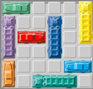
2. Rush Hour Game
The Goal: Drive the red car
out of the car park.
Sounds easy? Not really…
The Rush Hour® Game is a traffic game puzzle invented
by Nob Yoshigahara in the late 1970s. The goal is to drive the red car through
the exit (yellow arrow in diagram). In the game, cars and trucks are placed in
the 6 × 6 grid with the red car. Vertical vehicles can only move up/down, and
horizontal vehicles can only move left/right. By moving the vehicles in the
correct combination, the red car can be driven out. This puzzle has varying
levels of difficulty, and expert levels can become very complicated that one
requires over 40 moves to solve.

Image from http://www.igoweb.org/~wms/comp/
3. High Level Design
3.1 Hardware
Block Diagram Overview
The following block diagram
describes our basic hardware layout.

3.2
The following state machine
diagram provides an overview of our software
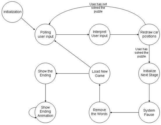
Figure: State Diagram for the
Rush Hour Game
The program flow is captured in a form of a state diagram like the one shown
above. It consists of 10 states: Initialization, poll, compute,
draw, next_stage, waiting, clearWords, loadGame,
ending, waiting2. An brief explanation of the states and
what they do are further explained below. For a complete description of the
algorithm used, please refer to a later section of the report for the details.
Initialization
In this state, the program
initializes the necessary hardware and software operators on different aspects
of the program. The different aspects are: video pulse synchronization, video
display, and signal reception from the touchpad. In video pulse
synchronization, Timer 1 is set up to generate sync pulses for the video
output. For video, the grid lines are drawn. The exit location is also
shown by printing the name “EXIT” on the screen corresponding to that
location. The difficulty of the current game is then displayed on the
screen right beside the word “LEVEL” on the top left corner of the
screen. The difficulty levels are represented from anything in the range
of 1 to 8, 1 being the simplest game and 8 being the most difficult. In
the initialization stage, the value that is being displayed is ‘1’.
poll – Poll inputs from
touchpad electrodes
At this state, the program
extracts the inputs from the 12 electrodes, from which the program will
determine the x-location and y-location of the cursor, and also find out if the
user intends to select a car. Once the polling is complete, the program
re-initializes the polling variables so that polling can take place again when
the state machine enters this state again. If the user indicates that he wants
to select a car, the program finds out if it is a valid selection, and which
car is selected. If the user were to release the select button, an car
that were selected previously would be de-selected. More on this later in
the report.
compute – Interpret User Input
The program enters this state,
acting on user input if a car were to be selected by the user. With a car
selected previously, the user indicates the new position that the selected car
should be. The program will then determine if the new position is
valid. If it is, the move is accepted. Otherwise, the move is
denied, and the car is kept at its current position. Note that the computation
is slightly different for horizontally placed cars than it is for vertically
placed cars.
draw – Update the locations of
the car in the video display.
If any changes were made to
the car positions, the changes would be reflected on the video display.
The updated location of the cursor is also reflected here. At this state,
the program also checks if the user has solved the puzzle. If the puzzle
has been solved, the program moves on to the next level.
next_stage – Moving on to the next level
In this state there are 2
phases. The program will first remove the cars from the previous stage,
and later it will show the message “CONGRATS LOADING NEXT STAGE”.
waiting – system pause
After the program displays the
message, it waits for an arbitrary amount of time before loading up a new
game. In this case the waiting time is 2.5 seconds.
clearWords – removing the message
After the system is done
waiting, it removes the congratulatory message from the video display in
preparation of loading a new game.
loadGame – loading a new game to
the video display
Once the congratulatory
message is removed, the program loads a new game to the video display.
ending – display shown when the
entire game is completed
When the player completes the
entire game, the program will detect that in the draw state. If
so, the program will remove the cars, the gridlines and the words “EXIT” and
“LEVEL XX”. Basically we will start with a blank screen. Later, the
congratulatory message “CONGRATS YOU R DONE” is shown on the
screen. An ending animation will be shown on the video display.
waiting2 – controlling the ending animation
This state basically controls
the movement of the cars in the ending animation.
3.3 Patents,
copyrights, and trademarks
We
are not using our project for any commercial purposes.
4. Hardware Design
4.1
Setting up the E-Field Sensors
For the E-field sensors, we used two MC33794D chips from
Freescale Semiconductor. Each MC33794 chip has 9 electrodes, but our game
requires 13 electrodes – 6 each for the rows and columns and 1 for select
button. Thus, two chips are used. 6 electrodes for the row are attached to the
first MC33794D chip, and 7 electrodes (including the select button) are
attached on the second chip.
Since E-field sensors are prone to noise and
instability, there are several physical and electrical considerations that must
be addressed in order for us to implement a reliable and functional playing
grid design.
The
MC33794D chip is an E-field / capacitive-based sensor
The chip contains nine sensor electrodes, each of
which will be grounded if not attached. An E-field sensor is also known as a
capacitive-based sensor. If two electric plates are separated by a distance d
and they have a potential difference of V, the electric field E is
![]()

Diagram of a Parallel Plate
Capacitor: Q => charge, E => electric field, d => distance
The capacitance C of a capacitor
with charge Q and –Q and potential difference V follows this general
equation
![]()
For a parallel plate
capacitor as shown on the right, the capacitance is given by
![]()
where ![]() is
the permittivity of the material in between the plates, A is the surface area
of the plates, and d is the distance separating the plates. The ratio of
the permittivity of the material X to air (free space) gives us the relative
dielectric constant of the material X. The dielectric constant gives us a
measurement of how much the material support electrostatic fields.
is
the permittivity of the material in between the plates, A is the surface area
of the plates, and d is the distance separating the plates. The ratio of
the permittivity of the material X to air (free space) gives us the relative
dielectric constant of the material X. The dielectric constant gives us a
measurement of how much the material support electrostatic fields.
The current that is flowing through the two plates
can be measured by this equation, where dV/dt is the rate of change of the
potential difference between the two plates.
![]()
The MC33794 makes use of these capacitive properties
to create an E-field sensor. If a wire is connected to the sensor electrode,
and nothing is near it, the voltage will remain high. But if a human finger
comes close to the wire, the e-field will naturally form a path to the finger and
to ground. This is because humans are mainly composed of water, which has a
high dielectric constant and is highly conductive as well due to the ionic
nature of water. This change in electric field current is registered by the
MC33794D and reflected as a change in output voltage in a pin labeled as LEVEL.
Since current I can only be present in when voltage V
is changing with time, the MC33794D Integrated Circuit is capable of generating
a sine-wave that is optimized at 120 Hz to prevent noise interference (60Hz).
More specific details regarding how the chips work and the technical data can
be found in the References section.
Size of
MC33794D Electrode Tradeoff
Attaching a conductive material to the wire to
increase the surface area for increased range and sensitivity is good. But as
the electrode size increases, so do the interference and noise effects
increase. This tradeoff is not easy to resolve, because the MC33794D is capable
of non-contact detection. In order to minimize noise and interference effects,
the MC33794 data sheet recommended designing the electrode to fit the surface
area of the object being detected – in our case, a human finger.
Therefore, we modeled our playing grid after the
actual playing grid of the Rush Hour game. Our square grids are 0.39 × 0.39
inch (1 × 1 cm) so that a human finger will be able to touch both the column
and row electrodes when placed on one grid.
Fringing
Effects due to Paired Electrodes
We plan to design and build the game board using a 2D
array of E-field sensors. This means that paired electrodes have to be used to
detect both the row and column of the player’s finger. Fringing effects occur
when paired electrodes are placed together. As seen in the following diagram,
the fringing field allows ungrounded objects to be detected in the “third”
dimension – the space above the 2D array. The larger the distance between the
two electrodes, the larger the fringing field.
 The Effects of Fringing and Distance
between Paired Electrodes
The Effects of Fringing and Distance
between Paired Electrodes
Final Design Decision
Taking into account the
above points, we decided not to increase the surface areas of our
electrodes. Since our paired electrodes are closely spaced (0.197 inch/
0.5 cm) within a grid, we cannot rely on the greatly reduced fringing effects
to detect the height dimension of the player’s fingers. The player must
therefore be physically touching the wires in order for the sensor to register
a change in current.
Building the 6×6 Playing Grid
In order to create a playing
board, we built a 6 × 6 cardboard grid that has wires running through each row
and each column. Our design follows the configuration as shown in the diagram.
Note that the horizontal and vertical wires do not touch at any point in time.
Also, there is no extra material placed on the electrodes as marked by E1, E2,
E3 and all the other electrodes in the diagram.

Column-Row Wire Configuration:
Diagram from Freescale AN1985 technical sheet
Since there are six rows and six columns, twelve electrodes
run through the grid as shown in the diagram (grid diagram and underside).
Since E-field sensors are used, all the wires cannot come into contact with
each other at any point in time as this causes interference and corrupts the
readings. Therefore, we wove the wires through the cardboard and inserted
strips of cardboard to prevent the wires from touching. See diagram (underside
of grid)

Figure: Diagram of 12 electrodes
running through the touchpad.
Note that at no point in the
setup do any 2 electrodes touch each other.

Figure: Underside of
Diagram.
Note how the vertical electrodes are
taped to provide electrical insulation from the horizontal electrodes.

Figure: Underside of
Diagram.
Strips of cardboard were added to increase
the electrical insulation between the vertical and horizontal electrodes.
Constructing the Select button
Simply put, the select
button is just another electrode that uses E-field sensors to detect the user
selection. For this project, it is just
a single wire that is taped onto the game board, which the user can then use to
select any car.
Transmitting
and Receiving the Sensor Signals
One MC33794D chip has one LEVEL pin that reads the
output from a selected electrode. This means that only one electrode output can
be polled at one time. How then does the MC33794D allow
polling for the other 8 electrodes?
The MC33794 chip has the following Electrode Selection Table in the technical
data sheet. ABCD are control pins of the MC33794D that allow the user to select
and poll a specific electrode. The table shows which electrode output will be
set in LEVEL after the control signals have been set. This emphasizes the need
for bi-directional communication between the MC33794D and the MCU.
|
TERMINAL/SIGNAL |
D |
C |
B |
A |
|
Source (internal) |
0 |
0 |
0 |
0 |
|
E1 |
0 |
0 |
0 |
1 |
|
E2 |
0 |
0 |
1 |
0 |
|
E3 |
0 |
0 |
1 |
1 |
|
E4 |
0 |
1 |
0 |
0 |
|
E5 |
0 |
1 |
0 |
1 |
|
E6 |
0 |
1 |
1 |
0 |
|
E7 |
0 |
1 |
1 |
1 |
|
E8 |
1 |
0 |
0 |
0 |
|
E9 |
1 |
0 |
0 |
1 |
We programmed the MCU to set ABCD to poll E1 to E6 in
the first MC33794D chip – this represents 6 rows of the grid. Next the MCU will
set ABCD to poll E1 to E7 on the second MC33794D chip to poll the 6 columns of
the grid and the select button. The MC33794D data sheet recommended that
LEVEL should be polled at least 1.5 ms after ABCD is set to allow for settling
time. Time is needed for the signal to settle down because a capacitor (LP_CAP)
is used filter the output noise in LEVEL.
Therefore, we set the polling interval in the
interrupt to be approximately 1.9ms. We obtained 1.9ms by setting the polling
period to occur once every 30 horizontal sync pulses are sent in the
interrupt as described in Dr. Bruce Land’s video code.
The video refreshes the screen at 60 frames/ second.
Hence 1 frame takes 63.6µs. The black-and-white television prints 262 lines per
frame. Therefore each polling period is
![]()
This allows for sufficient
time for the LEVEL output from the MC33794D to settle before polling its
result.
Railing
the LEVEL output
When a human finger is placed
on the polled electrode, the output voltage of LEVEL becomes 0 volts.
However, when the finger is removed, LEVEL reads 1.87 volts.
Initially, we considered using
the analog/digital converter (ADC) capability of the ATmega32 MCU so that we
can program the input signal (which is the LEVEL output) to be HIGH if it
exceeds a certain threshold voltage. However, upon consulting our TA Idan, we
realized that the ADC is used mainly for measuring a range of values that
require some degree of accuracy (e.g temperature). The ADC is not needed here
because we want the MCU to give us either a yes (1 – finger there) or a no (0 –
finger not there). We needed a circuit that can rail our output to 5V if the
finger is on the wire and 0V otherwise. This will enable the MCU to interpret
the 0 or 5V input easily.

Figure: Schematic of the
amplification circuit.
Note that it takes in the LEVEL output
from the MC33794 and inverts it, railing it from 0V to 5V.
We consulted Dr. Bruce, who
suggested that we use a general purpose amplifier –the 2N3904 NPN transistor.
Basically, the output voltage of the 2N3904 will read 5V if the input voltage
is less than 0.7V. If the input voltage is above 0.7V, the output voltage from
the 2N3904 will read 0V. The reaction time of the 2N3904 is around 35-50 ns,
which is insignificant compared to the settling time of the LEVEL output.
An NPN transistor was chosen because
of the behavior of LEVEL output. If the finger is on the polled electrode, the
LEVEL output was 0.07V. Since we wanted the MCU to read a HIGH (5V), the NPN
transistor serves as an excellent voltage inverter that is fast and accurate.
The NPN circuit gave railed outputs from 0V to 5.02V ~ 0V to 5V when the finger
left and touched the wire.
Minimizing
Wire Distance from MC33794 to MCU
We encountered some challenges
when we wired the grid output wires to the MC33794D. We secured the wires
neatly on the underside of a piece of cardboard that has our grid attached on
top. Even though the output read right when only one row is connected and
tested at a time, when all the rows are connected, the second grid row
dominated the output readings in the television.
We then discovered that the
length of the wires do play a critical role in ensuring a correct LEVEL output.
The previous design uses long wires which affected the capacitive property of the
wires. This resulted in the shortest wire (i.e. row 2) dominating the grid when
the MCU interprets the results. The wires were re-routed and shortened so as to
minimize the physical length of wire. The finalized setup for the
touchpad is given below.

Figure: Finalized setup for touchpad.
Note that the wires should not be too close,
otherwise it will influence each others’ E-field
5. Software Design
Making the Game Graphics
- Drawing the Grids on TV
36 grids are drawn on the TV
to simulate the playing field. Each grid is 14 × 14 pixels in dimension.
An “EXIT” sign is also printed beside the grid where the red car is supposed to
drive to in order to complete the game.
- Drawing the Cars on TV
Since our television is unable
to print in color, all our “non-red” vehicles are drawn in the same manner,
making them indistinguishable. Only the “red” car has to be distinct from the
other vehicles. Simply put, the “red” car as addressed in this project is the
car that anyone playing this game would want reach the exit point. One
can see from the following table that there are eight unique car “portions” in
this game.
|
|
|
|
|
|
|
|
|
|
Red Car Left |
Red Car Right |
Normal Car Left |
Normal Car Right |
Normal Car Top |
Normal Car Bottom |
Normal Car Middle |
Normal Car Middle |


From these basic structures,
we design our cars to get the following.
|
Length of Car |
Direction of Car |
Pictorial Representation |
|
2 grids – red car |
Horizontal (always) |
|
|
2 grids |
Horizontal |
|
|
2 grids |
Vertical |
|
|
3 grids |
Horizontal |
|
|
3 grids |
Vertical |
|
Initially, the cars were drawn
in a 13 × 13 array to fit into the 14 pixel × 14 pixel grid. Each grid can only
hold one car portion. After constructing 8 different car bodies, eight 13 × 13
arrays with the respective car bodies are created. The array elements can take
either a value of 1 to indicate lighting a television pixel and 0 to indicate
not lighting the pixel. We also modified the video code provided by Bruce Land
to print every pixel element of the car array on the television screen.
However, when we ran our code
to print the cars, the television displayed a blank screen. After some
calculations, we realized that there was simply not enough time to load every
pixel for all the cars and display it on the television. Each car portion
requires the checking of 169 pixels, and if all the cars occupy 15 grids in
total, more than 2500 pixels have to be checked to see if they contain a 0 or 1
before the game can be completely set up.
We decided that a more
efficient way to draw the cars is to hardcode each lighted pixel (i.e. pixel
value 1) for all the car portions. Thus we created eight functions for eight
unique car portions. Each function takes in three parameters: the reference x,
y coordinates, and how to draw the car (1 to draw; 0 to erase). To draw a car,
we need to specify the reference x, y location in order to place the car in the
correct grid, and we need to choose either to draw the car or erase it.
This method allows the cars to be drawn smoothly without any flickering of the
screen. When a car is selected and moved, one television frame is used for
computing and checking the validity of the new car move and one more frame is
used for erasing the old position and drawing the new position of the car.
Interfacing with Hardware
A small square cursor on the television screen tracks
the player’s finger when the finger comes in contact with one of the playing
grids. The cursor can take 36 positions as there are 36 grids. This increases
player-friendliness because the player does not need to refer to the grid as
his/her finger position will be displayed on the television screen.
Television Frame Management
Dr. Bruce Land’s video code writes at 60 frames a
second. We have to ensure that all operations should not occur during pixel
blasting. If the operations take too long, the pixel blasting loses its uniform
timing and the television will not display anything right. Therefore we
need to spread the computation, validation and drawing tasks across a few
frames to avoid any display failures that make the game unplayable. We assign
one frame each for the following tasks: the polling of the E-field sensors, the
computation and validation of a newly moved car and updating the new car
position and removing its old position.
Challenges in implementing Gameplay
In order for the game to be
functional, the following rules must be followed:
Cars that are horizontal can only move left or right
Cars that are vertical can only move up or down.
Cars must not overlap each other
Cars must always remain in the 6 × 6 grid
Implementing the rules is one of the hardest aspects
of the software design. This difficulty gets greater when we include player
participation. Listed here are several scenarios that can cause the game to
malfunction and how we resolved it:
- The user attempts to force and overlap between
Car A and Car B.
The new position of the car is
first checked with all other cars to make sure that no overlap occurs. If the
move is valid, the new car position is then stored and updated on the
television screen.
- The player selects car A and tries to overlap it with car B. Car A
will stop moving, but if the player randomly moves his/her finger around
the grid with the select button still pressed, visual artifacts
will appear on the screen and the game hangs.
If a car is
selected, as long as the select button is held on, the same car will remain
selected regardless of the grid the player chooses. This means if a horizontal
car A is on
Row 1, if
the select button is held on, the car A will
still be able to move left and right even if the player’s finger is on Row 5.
Due to the
fast polling rate of the sensors, the transition time for a finger to move
between grids creates transient results. If the transient results cause an
unintended grid to be
selected and the select
button is pressed, it may cause the wrong car to move and visual artifacts will
appear on the screen.
To eliminate
transient results, the polling result will not be updated unless both the grid
row and column yield a valid grid position.
6. Results
We are pleased with our efforts and the results that
we have obtained. In the time that we have committed in designing the
hardware and executing the code, we have managed to implement a fully
functional touchpad that is error-free. Also, we were able to structure
an intellectual game that is able to engage players of all levels. All in
all, this project has been a successful implementation of what would have been
an ideal project.
Speed of
execution (hesitation, flicker, interactiveness, concurrency)
The television display is crisp and clear. The
interactivity is dependent on both our hardware and software design, and this
resulted in a response time that is slightly slower than a human’s fast action.
Specifically, it is due to the limitations in the transition period between
selecting an electrode to be polled and actually retrieving the output.
If the user were to move his finger too fast, it is actually possible for the
wires of the sensors affect the E-field in ways that cause a particular row
reading to be dominant. This causes a mismatch between the cursor on the screen
and the finger position.
Safety
in the Design
The E-field sensors used in our project are low
powered and thus are considered safe. Also, we used Dr. Bruce Land’s video code
that conforms to the NTSC-RS170 standard. Hence there is no flickering on the
screen and will not cause any eye discomfort. Several people have
provided their input after trying the game, and no one actually mentioned any
flaws from the video output.
Interference
with other people's designs (e.g. cpu noise, RF
interference)
Our circuit does not have any components that emit or
cause interferences in other people’s design. In fact, our circuit is
susceptible to noise and electrical interferences.
Usability
This click-and-drag game is user-friendly and has simple
game controls. However, instructions have to be provided in order to minimize
confusion regarding the priority of controls. To move the desired car, the
player must first select the grid that the car is in and then press the select
button. If the player presses the select button first, he/she will not
be able to select any car. This control priority prevents any cars from being
unintentionally selected and from any resulting video artifacts.
7. Conclusions
Analyze your design in terms of how the results met
your expectations. What might you do differently next time?
Our game can be played smoothly without any video
artifacts, glitches or errors. We would, however, like to have faster reaction
times on our playing grids. If one’s fingers move too quickly, the MCU is not
able to display the current finger position in near real-time because we
designed our MCU to poll every row and column and calculate the grid where
finger is on before drawing our grid. In future, one can focus more on reducing
the settling time of the LEVEL output so as to give a faster response.
In addition, given more time and resources, we would
like to include better gaming graphics for visual attractiveness. Vehicles can
be color-coded, the grid can be colored and the cursor can be animated to
provide visual feedback to the player regarding the valid moves he/she can
make, or whether the player has made any invalid moves. Sound effects for
moving cars and winning a game can also be incorporated to enhance the gaming
experience.
If we had more time, it would be very nice to explore
the possibility of making this a 2-player game instead of just a one-player
game. Both players could pit their skills against one another, seeing who
can complete the game first.
Lastly, we would like to include useful game options
like “Restart Level,” “Undo Move” and maybe even “Hints.” These options are
quite standard in many software puzzle games, and including these into our
project would certainly score a plus point in our game design.
How did
your design conform to the applicable standards?
Dr. Bruce Land’s video code follows the NTSC-RS170
standard.
Intellectual
property considerations
We used Dr. Bruce Land’s video code to print our
grids and cars on a black-and-white television screen. Rush Hour® is a popular
puzzle game is played on several platforms. The two most common platforms are
the “hardware” version and the software version. The “hardware” version
resembles a board game where the grid is the board and the cars are the pieces.
The software versions are free online flash games that come in various
versions. Our novel design combines both hardware and software.
Ethical
Considerations
We committed to adhering to the IEEE Code of Ethics
for all our project design decisions and actions.
The first code applies to the safety, health and
welfare considerations of our design project. We accept full responsibility for
our design decisions and believe that our project will not cause any threat to
one’s safety, health or welfare. Special care is taken when we wire our
circuits to prevent any shorts or bad connections. The MC33794D is a low power
chip and hence does not pose any electrical hazards.
The third code emphasizes honesty when stating claims
or presenting data. We presented our report and design procedures, challenges
and solutions with full integrity. There are no hidden design aspects in our
project. Also, our design project does not involve simulation or data analysis.
No bribery of any forms was offered to or by us in
this project.
The seventh code addresses seeking, accepting and
offering honest criticism of technical work, and the giving of proper
accreditation to the work of others that we have used. Our TA suggested
building our own grid board instead of focusing on creating a two-player game.
We followed his suggestion and got started on understanding and using E-field
sensors in our project. In addition, all information sources are listed in the
References section.
All persons regardless of such factors as race,
religion, gender, disability, age, or national origin are treated fairly in the
course of our project. No one’s work, property, reputation or employment was
harmed in any way. We assisted some of our friends who are also doing their
final project by offering constructive comments and suggestions.
Acknowledgements:
We would also like to thank Dr. Bruce Land for his
tireless enthusiasm and assistance for the entire course of this semester, teaching
us all about using micro-controllers and freely providing us with the video
code that he written for the purposes of the course and our final project.
We would like to thank Freescale for the samples of
MC33794D and circuit boards that they have donated for the purpose of this
project. Without their generous donations, this project would have not
been implementable.
Finally, we would like to thank the TAs Idan Beck,
Waqqas Farooq, Kashif Javed, Donn Kim, Bryan Kressler, Varun Krishnan, Eric
Okawa, Donald Zhang, and the grader Sam Lee for their indiscriminating
assistance and advice throughout the entire duration of the course.
All in all, this course has been very
enjoyable. Thank you very much.
Appendix A: Schematics

Appendix B: Cost Details
|
Parts |
Subtotal Costs |
|
Freescale Semiconductor MC33794D |
$0 (sampled) |
|
Freescale Semiconductor Connector Board |
$0 (sampled) |
|
Bread Board (belongs to Chien Yi Chiu) |
$0 |
|
Grid Board (cardboard box, wires and tape) |
$0 |
|
2N3904 NPN Transistor |
$0 |
|
Small Black-and-White Television Set |
$5 ( rental) |
|
STK 500 board |
$15 |
|
Total Cost |
$20 |
Appendix C: Credits
In this entire project, both of us have put in equal
amounts of work. Any work that we did was fairly split in both amount and
complexity. As such, we both find it hard to actually allocate any part
of the project as specific to the efforts of any one individual. However, we may break down the work load as
shown below:
James Ang: Software - Game Design
Software - Website Design + Report Writeup
Software - Program Debugging
Hardware -
Hardware / Software Interface
Chien Yi Chiu: Hardware -
Touchpad Design
Hardware
-
Circuit Layout Design
Software
-
Program Structure
Software -
Schematics & Pictures
Appendix D: References
Dr. Bruce Land’s video code for
Atmel AVR controllers.
http://instruct1.cit.cornell.edu/courses/ee476/video/index.html
http://instruct1.cit.cornell.edu/courses/ee476/video/Video32v3.c
Game cards provided by the Rush Hour® game.
Atmel 8-bit AVR
Microcontroller datasheet.
2003.
http://instruct1.cit.cornell.edu/courses/ee476/AtmelStuff/full32.pdf
Motorola Electric Field
Imaging Device datasheet.
2004.
http://www.freescale.com/files/analog/doc/data_sheet/MC33794.pdf
http://instruct1.cit.cornell.edu/courses/ee476/
Pictures and Videos

Figure: This is what the
program loads when it first starts up
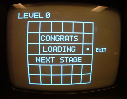
Figure: This display loads
when the user completes one puzzle before proceeding to the next level.

Figure: This display loads
when the user completes the entire game and stays there till the system is
reset.
Appendix E: Program Listing
//video gen
and sound
//D.5 is sync:1000
ohm + diode to 75 ohm resistor
//D.6 is
video:330 ohm + diode to 75 ohm resistor
#pragma
regalloc- //I allocate the registers myself
#pragma
optsize- //optimize for speed
#include
<Mega32.h>
#include
<stdio.h>
#include
<stdlib.h>
#include
<math.h>
#include
<delay.h>
//cycles =
63.625 * 16 Note NTSC is 63.55
//but this
line duration makes each frame exactly 1/60 sec
//which is
nice for keeping a realtime clock
#define
lineTime 1018
#define
begin {
#define
end }
#define
ScreenTop 30
#define
ScreenBot 230
#define
poll 0
#define
compute 1
#define
draw 2
#define
next_stage 3
#define
waiting 4
#define
clearWords 5
#define
loadGame 6
#define
ending 7
#define
waiting2 8
#define
horDirect 0
#define verDirect
1
#define
noDirect 2
#define
negDirect 3
#define
posDirect 4
//NOTE that
v1 to v8 and i must be in registers!
register
char v1 @4;
register
char v2 @5;
register
char v3 @6;
register
char v4 @7;
register
char v5 @8;
register
char v6 @9;
register
char v7 @10;
register
char v8 @11;
register int
i @12;
#pragma
regalloc+
char syncON,
syncOFF;
int
LineCount;
char
screen[1600];
char
cu1[]="EXIT"; //
4 characters
char
cu2[]="
"; // 2
characters
char
cu3[]="CONGRATS"; // 8 characters
char
cu4[]="LOADING"; // 7
characters
char
cu5[]="NEXT STAGE"; // 10 characters
char
cu6[]="YOU R DONE"; // 10 characters
char
cu7[]="LEVEL"; // 5
characters
char cu8[1];
unsigned
char ii,jj,kk;
// polling
variables
unsigned
char setDCBA; // DCBA value used to poll specific
electrode
int
pollCounter; //
cycles from 0 to 19 in polling cycle
unsigned
char poll_index; // index used for DCBAtable
unsigned int
pollValue[14]; // used to store polled outputs from LEVEL pin
unsigned
char pollDone; // 1 = poll for all 36 grids
complete, 0 = poll incomplete
char
gridNum, prevGrid, pollSel;
unsigned
char pressedX, pressedY, prevX, prevY;
// main
state diagram variables
unsigned
char main_state, congratsPrinted, loadingPrinted, nextPrinted;
unsigned
char newGame;
// car
variables
char fixXY,
carOverlap, carStart, carEnd, carRow, carCol, carMoved, lockDirection;
unsigned
char carX,
unsigned
char carSelectedFlag;
unsigned char
carStartTemp, carEndTemp, carMidTemp, prevCarStart, prevCarEnd;
// declare
functions
void
getGrid(void);
void
updateCursor(void);
void
displayCursor(void);
void
removeCursor(void);
void
refreshCars(void);
void
getCarPos(void);
void
updateCar(void);
void
removeCar(void);
void
removeRedCar(void);
void
refreshRedCar(void);
void
clearAllCars(int);
void
drawCar(int);
void
drawRedCar(int ii,char c);
#define
r_index 14
#define
c_index 14
// set up
carVector, a vector that stores the start and end grid positions of the cars
// the red
car's start and end position MUST be the first two values in the vector
char
carVectors[8][23] = { 8,14,15, 1, 2, 6,12, 7,13, 4,10,25,31,29,30,33,35, 0, 0,
0, 0, 0, 0,
6,14,15,22,28,20,21,26,32,33,34,24,36, 0, 0, 0, 0, 0, 0, 0, 0, 0, 0,
9,14,15, 1, 2, 7, 8,13,25,31,33,26,27,20,22, 3, 9, 4,16, 0, 0, 0, 0,
8,15,16, 3, 9, 4, 5,14,20,26,28,21,22,11,17,23,29, 0, 0, 0, 0, 0, 0,
10,16,17, 3, 5, 9,15,10,11,21,27,22,28, 6,18,23,24,29,30,33,35, 0, 0,
7,14,15, 1, 2, 3, 9, 7,19,20,22, 4,16,34,36, 0, 0, 0, 0, 0, 0, 0, 0,
11,13,14, 1, 7, 8, 9,15,21,27,33, 4, 6,10,16,22,23,28,29,34,36,18,30,
11,13,14,19,25,31,32,26,27,20,22, 3,15,10,16, 4, 5, 6,18,28,34,29,35};
char
carVector[23];
// Store the
DCBA values that are used to set the electode E1 - E6 and select button for
polling
flash char
DCBAtable[14] = {0x01, 0x02, 0x03, 0x04, 0x05, 0x06,
0x10, 0x20, 0x30, 0x40, 0x50, 0x60, 0x70, 0x00};
//Point plot
lookup table
//One bit
masks
flash char
pos[8]={0x80,0x40,0x20,0x10,0x08,0x04,0x02,0x01};
// LEFT ARC
- x,y car coordinates with (1,1) as reference point
flash char
leftarc_y[29] =
{5,6,7,8,9,3,4,10,11,2,12,2,12,2,12,2,12,2,12,2,12,2,12,2,12,2,12,2,12};
flash char
leftarc_x[29] = {2,2,2,2,2,3,3,3,3,4,4,5,5,6,6,7,7,8,8,9,9,10,10,11,11,12,12,13,13};
// RIGHT ARC
- x,y car coordinates with (1,1) as reference point
flash char
rightarc_y[29] =
{2,12,2,12,2,12,2,12,2,12,2,12,2,12,2,12,2,12,2,12,3,4,10,11,5,6,7,8,9};
flash char
rightarc_x[29] = {1,1,2,2,3,3,4,4,5,5,6,6,7,7,8,8,9,9,10,10,11,11,11,11,12,12,12,12,12};
//
HORIZONTAL BODY - x,y car coordinates with (1,1) as reference point
flash char
hor_y[26] =
{2,12,2,12,2,12,2,12,2,12,2,12,2,12,2,12,2,12,2,12,2,12,2,12,2,12};
flash char
hor_x[26] = {1,1,2,2,3,3,4,4,5,5,6,6,7,7,8,8,9,9,10,10,11,11,12,12,13,13};
// TOP ARC -
x,y car coordinates with (1,1) as reference point
flash char
toparc_y[27] =
{5,6,7,8,9,10,11,12,13,4,3,2,2,2,2,2,3,4,5,6,7,8,9,10,11,12,13};
flash char
toparc_x[27] = {2,2,2,2,2,2,2,2,2,3,4,5,6,7,8,9,10,11,12,12,12,12,12,12,12,12,12};
// BOTTOM
ARC - x,y car coordinates with (1,1) as reference point
flash char
botarc_y[27] =
{1,2,3,4,5,6,7,8,9,10,11,12,12,12,12,12,11,10,1,2,3,4,5,6,7,8,9};
flash char
botarc_x[27] = {2,2,2,2,2,2,2,2,2,3,4,5,6,7,8,9,10,11,12,12,12,12,12,12,12,12,12};
// VERTICAL
BODY - x,y car coordinates with (1,1) as reference point
flash char
ver_y[26] =
{1,2,3,4,5,6,7,8,9,10,11,12,13,1,2,3,4,5,6,7,8,9,10,11,12,13};
flash char
ver_x[26] = {2,2,2,2,2,2,2,2,2,2,2,2,2,12,12,12,12,12,12,12,12,12,12,12,12,12};
// RED CAR
LEFT ARC - x,y car coordinates with (1,1) as reference point
flash char
red_leftarc_y[52] =
{5,6,7,8,9,3,4,10,11,2,6,7,8,12,2,4,5,9,10,12,2,4,10,12,2,4,10,12,2,4,10,12,2,4,10,12,2,4,10,12,2,4,10,12,2,4,10,12,2,4,10,12};
flash char
red_leftarc_x[52] =
{2,2,2,2,2,3,3,3,3,4,4,4,4,4,5,5,5,5,5,5,6,6,6,6,7,7,7,7,8,8,8,8,9,9,9,9,10,10,10,10,11,11,11,11,12,12,12,12,13,13,13,13};
// RED CAR
RIGHT ARC - x,y car coordinates with (1,1) as reference point
flash char
red_rightarc_y[52] =
{2,4,10,12,2,4,10,12,2,4,10,12,2,4,10,12,2,4,10,12,2,4,10,12,2,4,10,12,2,4,10,12,2,4,5,9,10,12,2,6,7,8,12,3,4,10,11,5,6,7,8,9};
flash char
red_rightarc_x[52] = {1,1,1,1,2,2,2,2,3,3,3,3,4,4,4,4,5,5,5,5,6,6,6,6,7,7,7,7,8,8,8,8,9,9,9,9,9,9,10,10,10,10,10,11,11,11,11,12,12,12,12,12};
//define
some character bitmaps
//5x7
characters
flash char
bitmap[39][7]={
//0 1
0b01110000,
0b10001000,
0b10011000,
0b10101000,
0b11001000,
0b10001000,
0b01110000,
//1 2
0b00100000,
0b01100000,
0b00100000,
0b00100000,
0b00100000,
0b00100000,
0b01110000,
//2 3
0b01110000,
0b10001000,
0b00001000,
0b00010000,
0b00100000,
0b01000000,
0b11111000,
//3 4
0b11111000,
0b00010000,
0b00100000,
0b00010000,
0b00001000,
0b10001000,
0b01110000,
//4 5
0b00010000,
0b00110000,
0b01010000,
0b10010000,
0b11111000,
0b00010000,
0b00010000,
//5 6
0b11111000,
0b10000000,
0b11110000,
0b00001000,
0b00001000,
0b10001000,
0b01110000,
//6 7
0b01000000,
0b10000000,
0b10000000,
0b11110000,
0b10001000,
0b10001000,
0b01110000,
//7 8
0b11111000,
0b00001000,
0b00010000,
0b00100000,
0b01000000,
0b10000000,
0b10000000,
//8 9
0b01110000,
0b10001000,
0b10001000,
0b01110000,
0b10001000,
0b10001000,
0b01110000,
//9 10
0b01110000,
0b10001000,
0b10001000,
0b01111000,
0b00001000,
0b00001000,
0b00010000,
//A 11
0b01110000,
0b10001000,
0b10001000,
0b10001000,
0b11111000,
0b10001000,
0b10001000,
//B 12
0b11110000,
0b10001000,
0b10001000,
0b11110000,
0b10001000,
0b10001000,
0b11110000,
//C 13
0b01110000,
0b10001000,
0b10000000,
0b10000000,
0b10000000,
0b10001000,
0b01110000,
//D 14
0b11110000,
0b10001000,
0b10001000,
0b10001000,
0b10001000,
0b10001000,
0b11110000,
//E 15
0b11111000,
0b10000000,
0b10000000,
0b11111000,
0b10000000,
0b10000000,
0b11111000,
//F 16
0b11111000,
0b10000000,
0b10000000,
0b11111000,
0b10000000,
0b10000000,
0b10000000,
//G 17
0b01110000,
0b10001000,
0b10000000,
0b10011000,
0b10001000,
0b10001000,
0b01110000,
//H 18
0b10001000,
0b10001000,
0b10001000,
0b11111000,
0b10001000,
0b10001000,
0b10001000,
//I 19
0b01110000,
0b00100000,
0b00100000,
0b00100000,
0b00100000,
0b00100000,
0b01110000,
//J 20
0b00111000,
0b00010000,
0b00010000,
0b00010000,
0b00010000,
0b10010000,
0b01100000,
//K 21
0b10001000,
0b10010000,
0b10100000,
0b11000000,
0b10100000,
0b10010000,
0b10001000,
//L 22
0b10000000,
0b10000000,
0b10000000,
0b10000000,
0b10000000,
0b10000000,
0b11111000,
//M 23
0b10001000,
0b11011000,
0b10101000,
0b10101000,
0b10001000,
0b10001000,
0b10001000,
//N 24
0b10001000,
0b10001000,
0b11001000,
0b10101000,
0b10011000,
0b10001000,
0b10001000,
//O 25
0b01110000,
0b10001000,
0b10001000,
0b10001000,
0b10001000,
0b10001000,
0b01110000,
//P 26
0b11110000,
0b10001000,
0b10001000,
0b11110000,
0b10000000,
0b10000000,
0b10000000,
//Q 27
0b01110000,
0b10001000,
0b10001000,
0b10001000,
0b10101000,
0b10010000,
0b01101000,
//R 28
0b11110000,
0b10001000,
0b10001000,
0b11110000,
0b10100000,
0b10010000,
0b10001000,
//S 29
0b01111000,
0b10000000,
0b10000000,
0b01110000,
0b00001000,
0b00001000,
0b11110000,
//T 30
0b11111000,
0b00100000,
0b00100000,
0b00100000,
0b00100000,
0b00100000,
0b00100000,
//U 31
0b10001000,
0b10001000,
0b10001000,
0b10001000,
0b10001000,
0b10001000,
0b01110000,
//V 32
0b10001000,
0b10001000,
0b10001000,
0b10001000,
0b10001000,
0b01010000,
0b00100000,
//W 33
0b10001000,
0b10001000,
0b10001000,
0b10101000,
0b10101000,
0b10101000,
0b01010000,
//X 34
0b10001000,
0b10001000,
0b01010000,
0b00100000,
0b01010000,
0b10001000,
0b10001000,
//Y 35
0b10001000,
0b10001000,
0b10001000,
0b01010000,
0b00100000,
0b00100000,
0b00100000,
//Z 36
0b11111000,
0b00001000,
0b00010000,
0b00100000,
0b01000000,
0b10000000,
0b11111000,
//figure1 37
0b01110000,
0b00100000,
0b01110000,
0b10101000,
0b00100000,
0b01010000,
0b10001000,
//figure2 38
0b01110000,
0b10101000,
0b01110000,
0b00100000,
0b00100000,
0b01010000,
0b10001000,
//space 39
0b00000000,
0b00000000,
0b00000000,
0b00000000,
0b00000000,
0b00000000,
0b00000000};
//copy to
the screen at x-position divisible by 4
flash char
smallbitmap[39][5]={
//0
0b11101110,
0b10101010,
0b10101010,
0b10101010,
0b11101110,
//1
0b01000100,
0b11001100,
0b01000100,
0b01000100,
0b11101110,
//2
0b11101110,
0b00100010,
0b11101110,
0b10001000,
0b11101110,
//3
0b11101110,
0b00100010,
0b11101110,
0b00100010,
0b11101110,
//4
0b10101010,
0b10101010,
0b11101110,
0b00100010,
0b00100010,
//5
0b11101110,
0b10001000,
0b11101110,
0b00100010,
0b11101110,
//6
0b11001100,
0b10001000,
0b11101110,
0b10101010,
0b11101110,
//7
0b11101110,
0b00100010,
0b01000100,
0b10001000,
0b10001000,
//8
0b11101110,
0b10101010,
0b11101110,
0b10101010,
0b11101110,
//9
0b11101110,
0b10101010,
0b11101110,
0b00100010,
0b01100110,
//:
0b00000000,
0b01000100,
0b00000000,
0b01000100,
0b00000000,
//=
0b00000000,
0b11101110,
0b00000000,
0b11101110,
0b00000000,
//blank
0b00000000,
0b00000000,
0b00000000,
0b00000000,
0b00000000,
//A
0b11101110,
0b10101010,
0b11101110,
0b10101010,
0b10101010,
//B
0b11001100,
0b10101010,
0b11101110,
0b10101010,
0b11001100,
//C
0b11101110,
0b10001000,
0b10001000,
0b10001000,
0b11101110,
//D
0b11001100,
0b10101010,
0b10101010,
0b10101010,
0b11001100,
//E
0b11101110,
0b10001000,
0b11101110,
0b10001000,
0b11101110,
//F
0b11101110,
0b10001000,
0b11101110,
0b10001000,
0b10001000,
//G
0b11101110,
0b10001000,
0b10001000,
0b10101010,
0b11101110,
//H
0b10101010,
0b10101010,
0b11101110,
0b10101010,
0b10101010,
//I
0b11101110,
0b01000100,
0b01000100,
0b01000100,
0b11101110,
//J
0b00100010,
0b00100010,
0b00100010,
0b10101010,
0b11101110,
//K
0b10001000,
0b10101010,
0b11001100,
0b11001100,
0b10101010,
//L
0b10001000,
0b10001000,
0b10001000,
0b10001000,
0b11101110,
//M
0b10101010,
0b11101110,
0b11101110,
0b10101010,
0b10101010,
//N
0b00000000,
0b11001100,
0b10101010,
0b10101010,
0b10101010,
//O
0b01000100,
0b10101010,
0b10101010,
0b10101010,
0b01000100,
//P
0b11101110,
0b10101010,
0b11101110,
0b10001000,
0b10001000,
//Q
0b01000100,
0b10101010,
0b10101010,
0b11101110,
0b01100110,
//R
0b11101110,
0b10101010,
0b11001100,
0b11101110,
0b10101010,
//S
0b11101110,
0b10001000,
0b11101110,
0b00100010,
0b11101110,
//T
0b11101110,
0b01000100,
0b01000100,
0b01000100,
0b01000100,
//U
0b10101010,
0b10101010,
0b10101010,
0b10101010,
0b11101110,
//V
0b10101010,
0b10101010,
0b10101010,
0b10101010,
0b01000100,
//W
0b10101010,
0b10101010,
0b11101110,
0b11101110,
0b10101010,
//X
0b00000000,
0b10101010,
0b01000100,
0b01000100,
0b10101010,
//Y
0b10101010,
0b10101010,
0b01000100,
0b01000100,
0b01000100,
//Z
0b11101110,
0b00100010,
0b01000100,
0b10001000,
0b11101110
};
//==================================
//This is
the sync generator and raster generator. It MUST be entered from
//sleep mode
to get accurate timing of the sync pulses
#pragma
warn-
interrupt
[TIM1_COMPA] void t1_cmpA(void)
begin
//start the Horizontal sync pulse
PORTD
= syncON;
//update the curent scanline number
LineCount ++ ;
//begin inverted (Vertical) synch after line 247
if
(LineCount==248)
begin
syncON = 0b00100000;
syncOFF = 0;
end
//back
to regular sync after line 250
if
(LineCount==251)
begin
syncON = 0;
syncOFF = 0b00100000;
end
//start new frame after line 262
if
(LineCount==263)
begin
LineCount = 1;
end
delay_us(2);
//adjust to make 5 us pulses
//end
sync pulse
PORTD
= syncOFF;
if
(LineCount<ScreenBot && LineCount>=ScreenTop)
begin
//compute byte index for beginning of the next line
//left-shift 4 would be individual lines
// <<3 means line-double the pixels
//The 0xfff8 truncates the odd line bit
//i=(LineCount-ScreenTop)<<3 & 0xfff8; //
#asm
push r16
lds r12, _LineCount
lds r13, _Linecount+1
ldi r16, 30
sub r12, r16
ldi r16,0
sbc r13, r16
lsl r12
rol r13
lsl r12
rol r13
lsl r12
rol r13
mov r16,r12
andi r16,0xf0
mov r12,r16
pop r16
#endasm
//load 16 registers with screen info
#asm
push r14
push r15
push r16
push r17
push r18
push r19
push r26
push r27
ldi r26,low(_screen) ;base address of screen
ldi r27,high(_screen)
add
r26,r12 ;offset
into screen (add i)
adc r27,r13
ld r4,x+
;load 16 registers and inc pointer
ld r5,x+
ld r6,x+
ld r7,x+
ld r8,x+
ld r9,x+
ld r10,x+
ld r11,x+
ld r12,x+
ld r13,x+
ld r14,x+
ld r15,x+
ld r16,x+
ld r17,x+
ld r18,x+
ld r19,x
pop r27
pop r26
#endasm
delay_us(4); //adjust to center image on screen
//blast 16 bytes to the screen
#asm
;but first a macro to make the code shorter
;the macro takes a register number as a parameter
;and dumps its bits serially to portD.6
;the nop can be eliminated to make the display narrower
.macro videobits ;regnum
BST @0,7
IN R30,0x12
BLD R30,6
nop
OUT 0x12,R30
BST @0,6
IN R30,0x12
BLD R30,6
nop
OUT 0x12,R30
BST @0,5
IN R30,0x12
BLD R30,6
nop
OUT 0x12,R30
BST @0,4
IN R30,0x12
BLD R30,6
nop
OUT 0x12,R30
BST @0,3
IN R30,0x12
BLD R30,6
nop
OUT 0x12,R30
BST @0,2
IN R30,0x12
BLD R30,6
nop
OUT 0x12,R30
BST @0,1
IN R30,0x12
BLD R30,6
nop
OUT 0x12,R30
BST @0,0
IN R30,0x12
BLD R30,6
nop
OUT 0x12,R30
.endm
videobits r4 ;video line -- byte 1
videobits r5 ;byte 2
videobits r6 ;byte 3
videobits r7 ;byte 4
videobits r8 ;byte 5
videobits r9 ;byte 6
videobits r10 ;byte 7
videobits r11 ;byte 8
videobits r12 ;byte 9
videobits r13 ;byte 10
videobits r14 ;byte 11
videobits r15 ;byte 12
videobits r16 ;byte 13
videobits r17 ;byte 14
videobits r18 ;byte 15
videobits r19 ;byte 16
clt ;clear video after the last pixel on the line
IN R30,0x12
BLD R30,6
OUT 0x12,R30
pop r19
pop r18
pop r17
pop r16
pop r15
pop r14
#endasm
end
// poll current DCBA electrode value and set the electrode
if(!pollDone)
begin
pollCounter++;
if(pollCounter == 30)
begin
// NPN 2N3904 transistor gives 5V when input is LO and 0V when input is HI
if(poll_index<=5) pollValue[poll_index++] = PIND.0;
else
begin
pollValue[poll_index++] = PIND.1;
#asm
nop
nop
nop
nop
#endasm
end
setDCBA = DCBAtable[poll_index];
PORTC =
setDCBA;
// Set the PORTC to select the electrode
pollCounter = 0;
end
else
begin
// need to pad with more nops -- K&J must pad
#asm
nop
nop
nop
nop
nop
nop
nop
#endasm
end
pollDone = (setDCBA == 0x00);
end
else
begin
// need to pad with more nops -- K&J must pad
#asm
nop
nop
nop
nop
nop
nop
nop
nop
nop
nop
nop
nop
nop
nop
nop
nop
nop
nop
nop
nop
nop
nop
nop
nop
nop
nop
nop
nop
nop
nop
nop
nop
nop
nop
nop
nop
nop
nop
nop
nop
nop
nop
nop
nop
nop
#endasm
end
end
#pragma
warn+
//==================================
//plot one
point
//at x,y
with color 1=white 0=black 2=invert
#pragma
warn-
void
video_pt(char x, char y, char c)
begin
#asm
; i=(x>>3) + ((int)y<<4) ; the byte with the
pixel in it
push r16
ldd r30,y+2
;get x
lsr r30
lsr r30
lsr r30
;divide x by 8
ldd r12,y+1
;get y
lsl
r12
;mult y by 16
clr r13
lsl r12
rol r13
lsl r12
rol r13
lsl r12
rol r13
add r12, r30 ;add
in x/8
;v2 = screen[i]; r5
;v3 = pos[x & 7]; r6
;v4 = c r7
ldi r30,low(_screen)
ldi r31,high(_screen)
add r30, r12
adc r31, r13
ld r5,Z
;get screen byte
ldd r26,y+2
;get x
ldi r27,0
andi r26,0x07 ;form
x & 7
ldi r30,low(_pos*2)
ldi r31,high(_pos*2)
add r30,r26
adc r31,r27
lpm r6,Z
ld r16,y
;get c
;if (v4==1) screen[i] = v2 | v3 ;
;if (v4==0) screen[i] = v2 & ~v3;
;if (v4==2) screen[i] = v2 ^ v3 ;
cpi r16,1
brne tst0
or r5,r6
tst0:
cpi r16,0
brne tst2
com r6
and r5,r6
tst2:
cpi r16,2
brne writescrn
eor r5,r6
writescrn:
ldi r30,low(_screen)
ldi r31,high(_screen)
add r30, r12
adc r31, r13
st Z, r5
;write the
byte back to the screen
pop r16
#endasm
end
#pragma
warn+
//==================================
//
Length-2 Horizontal car - draw (c = 1) or remove (c = 0)
void video_car2H(char
x, char y, char c)
begin
v7 = x;
v8 = y;
for(v6=0;v6<29;v6++)
begin
video_pt(v7
+ leftarc_x[v6] , v8 + leftarc_y[v6] ,c);
video_pt(v7+ c_index + rightarc_x[v6] , v8 + rightarc_y[v6] ,c);
end
end
//==================================
//
Length-3 Horizontal car - draw (c = 1) or remove (c = 0)
void
video_car3H(char x, char y, char c)
begin
v7 = x;
v8 = y;
// constrained by horizontal vector length of 26
for(v6=0;v6<26;v6++)
begin
video_pt(v7 +
leftarc_x[v6]
, v8 + leftarc_y[v6] ,c);
video_pt(v7+ c_index +
hor_x[v6]
, v8 + hor_y[v6] ,c);
video_pt(v7+ c_index + c_index + rightarc_x[v6] , v8 +
rightarc_y[v6] ,c);
end
// finish up the remaining vector elements
for(v6=26;v6<29;v6++)
begin
video_pt(v7 +
leftarc_x[v6]
, v8 + leftarc_y[v6] ,c);
video_pt(v7+ c_index + c_index + rightarc_x[v6] , v8 +
rightarc_y[v6] ,c);
end
end
//==================================
//
Length-2 Vertical car - draw (c = 1) or remove (c = 0)
void
video_car2V(char x, char y, char c)
begin
v7 = x;
v8 = y;
for(v6=0;v6<27;v6++)
begin
video_pt(v7 + toparc_x[v6] , v8 +
toparc_y[v6]
,c);
video_pt(v7 + botarc_x[v6] , v8 + r_index + botarc_y[v6] ,c);
end
end
//==================================
//
Length-3 Vertical car - draw (c = 1) or remove (c = 0)
void
video_car3V(char x, char y, char c)
begin
v7 = x;
v8 = y;
// constrained by vertical vector length of 26
for(v6=0;v6<26;v6++)
begin
video_pt(v7 + toparc_x[v6] , v8 + toparc_y[v6]
,c);
video_pt(v7 + ver_x[v6] , v8 + r_index +
ver_y[v6]
,c);
video_pt(v7 + botarc_x[v6] , v8 + r_index + r_index +
botarc_y[v6] ,c);
end
// finish up remaining vector elements
video_pt(v7 + toparc_x[26] , v8 +
toparc_y[26]
,c);
video_pt(v7 + botarc_x[26] , v8 + r_index + r_index +
botarc_y[26] ,c);
end
//==================================
//
Length-2 Red Car - always horizontal - draw (c = 1) or remove (c = 0)
void
video_car2R(char x, char y, char c)
begin
v7 = x;
v8 = y;
for(v6=0;v6<52;v6++)
begin
video_pt(v7 +
red_leftarc_x[v6]
, v8 + red_leftarc_y[v6] ,c);
video_pt(v7 + c_index + red_rightarc_x[v6] , v8 +
red_rightarc_y[v6] ,c);
end
end
//==================================
// put a big
character on the screen
// c is
index into bitmap
void
video_putchar(char x, char y, char c)
begin
v7 = x;
for (v6=0;v6<7;v6++)
begin
v1 = bitmap[c][v6];
v8 = y+v6;
video_pt(v7, v8, (v1 & 0x80)==0x80);
video_pt(v7+1, v8, (v1 & 0x40)==0x40);
video_pt(v7+2, v8, (v1 & 0x20)==0x20);
video_pt(v7+3, v8, (v1 & 0x10)==0x10);
video_pt(v7+4, v8, (v1 & 0x08)==0x08);
end
end
//==================================
// put a
string of big characters on the screen
void
video_puts(char x, char y, char *str)
begin
char i ;
for (i=0; str[i]!=0; i++)
begin
if(str[i]==0x20) video_putchar(x,y,38);
else if (str[i]>=0x30 && str[i]<=0x3a)
video_putchar(x,y,str[i]-0x30);
else video_putchar(x,y,str[i]-0x40+9);
x = x+6;
end
end
//==================================
// put a
small character on the screen
// x-cood
must be on divisible by 4
// c is
index into bitmap
void
video_smallchar(char x, char y, char c)
begin
char mask;
i=((int)x>>3) + ((int)y<<4) ;
if (x == (x & 0xf8)) mask = 0x0f; //f8
else mask = 0xf0;
screen[i] = (screen[i] & mask) | (smallbitmap[c][0] &
~mask);
screen[i+16] = (screen[i+16] & mask) | (smallbitmap[c][1] & ~mask);
screen[i+32] = (screen[i+32] & mask) | (smallbitmap[c][2] & ~mask);
screen[i+48] = (screen[i+48] & mask) | (smallbitmap[c][3] & ~mask);
screen[i+64] = (screen[i+64] & mask) | (smallbitmap[c][4] & ~mask);
end
//==================================
// put a
string of small characters on the screen
// x-cood
must be on divisible by 4
void
video_putsmalls(char x, char y, char *str)
begin
char i ;
for (i=0; str[i]!=0; i++)
begin
if (str[i]==0x20) video_smallchar(x,y,12);
else if (str[i]>=0x30 && str[i]<=0x3a)
video_smallchar(x,y,str[i]-0x30);
else video_smallchar(x,y,str[i]-0x40+12);
x = x+4;
end
end
//==================================
//plot a
line
//at x1,y1
to x2,y2 with color 1=white 0=black 2=invert
//NOTE: this
function requires signed chars
void
video_line(char x1, char y1, char x2, char y2, char c)
begin
int e;
signed char dx,dy,j, temp;
signed char s1,s2, xchange;
signed char x,y;
x = x1;
y = y1;
dx = cabs(x2-x1);
dy = cabs(y2-y1);
s1 = csign(x2-x1);
s2 = csign(y2-y1);
xchange = 0;
if (dy>dx)
begin
temp = dx;
dx = dy;
dy = temp;
xchange = 1;
end
e = ((int)dy<<1) - dx;
for (j=0; j<=dx; j++)
begin
video_pt(x,y,c) ;
if (e>=0)
begin
if (xchange==1) x = x + s1;
else y = y + s2;
e = e - ((int)dx<<1);
end
if (xchange==1) y = y + s2;
else x = x + s1;
e = e + ((int)dy<<1);
end
end
//==================================
// set up
the ports and timers
void
main(void)
begin
//init timer 1 to generate sync
OCR1A = lineTime;
// One NTSC
line
TCCR1B = 9;
// full speed; clear-on-match
TCCR1A =
0x00;
// turn off pwm and oc lines
TIMSK =
0x10;
// enable interrupt T1 cmp
//init ports
DDRD =
0xf0;
// video out and switches
DDRC = 0xff; // set PORTC as output
//D.5 is sync:1000 ohm + diode to 75 ohm resistor
//D.6 is video:330 ohm + diode to 75 ohm resistor
//D.0 is input from LEVEL pin in both row and col capacitor sensors
//initialize synch constants
LineCount = 1;
syncON = 0b00000000;
syncOFF = 0b00100000;
//draw the lines
for(ii=1;ii<8;ii++)
video_line(ii*c_index,r_index,ii*c_index,7*r_index,1); // vertical lines
for(ii=1;ii<8;ii++) video_line(c_index,ii*r_index,7*c_index,ii*r_index,1);
// horizontal lines
// load carVector
for(ii=0;ii<23;ii++) carVector[ii] = carVectors[0][ii];
// print "exit" sign to denote where red car should be in order to
win game
video_putsmalls(8*c_index-8, 3*r_index+6, cu1);
// display the current level
video_puts(3,3,cu7);
video_putchar(35,3,newGame);
// draw the cars
refreshRedCar();
refreshCars();
// init polling interrupt
poll_index = 0;
setDCBA = DCBAtable[poll_index];
PORTC = setDCBA;
pollCounter = 0;
pollDone = 0;
// init main variables
prevGrid = 1;
gridNum = 1;
carStart = 0;
carEnd = 0;
carRow = 0;
carCol = 0;
carX = 0;
fixXY = noDirect;
lockDirection = noDirect;
newGame = 0;
// init next_stage variables
congratsPrinted = 0;
loadingPrinted = 0;
nextPrinted = 0;
//enable sleep mode
MCUCR = 0b10000000;
#asm ("sei");
//The following loop executes once/video line during lines
//1-230, then does all of the frame-end processing
while(1)
begin
#asm ("sleep");
if (LineCount==231)
begin
switch(main_state)
begin
case poll:
if(pollDone)
// poll only if it is okie to poll
begin
getGrid();
// cursor's x_loc, y_loc; user select?
poll_index = 0;
// reset DCBAtable index
setDCBA = DCBAtable[poll_index]; // reset the first item to be polled
PORTC= setDCBA;
// reset PORTC to receive input
pollCounter = 0;
// reset the polling counter
end
// if no car has
been selected yet, select a car.
if ((pollSel==1) && (carSelectedFlag==0))
getCarPos();
// if the user released the select button deselect the car
if(pollSel==0)
begin
carSelectedFlag = 0;
carOverlap = 0;
lockDirection = noDirect;
fixXY = 2;
end
main_state = compute;
break;
case compute:
// if a car has been selected by player
if(carSelectedFlag)
begin
// check how much the car has moved
carMoved = gridNum - prevGrid;
prevCarStart = carStart;
prevCarEnd = carEnd;
if(fixXY==0)
// selected car is horizontal
begin
switch(carMoved)
begin
case 1: // move right 1
if((carEnd%6)!=0)
begin
carStart++;
carEnd++;
end
break;
case -1: // move left 1
if((carStart%6)!=1)
begin
carStart--;
carEnd--;
end
break;
end
end
else if(fixXY==1) // selected car is vertical
begin
switch(carMoved)
begin
case 6: // move down 1
if(((carEnd-1)/6)!=5)
begin
carStart+=6;
carEnd+=6;
end
break;
case -6: // move up 1
if(((carStart-1)/6)!=0)
begin
carStart-=6;
carEnd-=6;
end
break;
end
end
// if overlap previously detected, do stuff.
if(carOverlap==1)
begin
if((prevGrid>gridNum && lockDirection==posDirect) ||
(gridNum>prevGrid && lockDirection==negDirect))
begin
carOverlap=0;
lockDirection=noDirect;
end
end
// check moved car does not overlap on another car
if(carOverlap==0)
begin
for(ii=1;ii<(2*carVector[0]+1);ii+=2)
begin
if(ii!=carIndex)
begin
carStartTemp = carVector[ii];
carEndTemp = carVector[ii+1];
carMidTemp
= (carStartTemp + carEndTemp)/2;
carOverlap
= carOverlap || (carStart==carStartTemp) || (carStart==carEndTemp);
carOverlap
= carOverlap || (carEnd==carStartTemp) || (carEnd==carEndTemp);
carOverlap
= carOverlap || ((carEndTemp-carStartTemp==2 || carEndTemp-carStartTemp==12)&&(carEnd==carMidTemp
|| carStart==carMidTemp));
end // (ii!=carIndex)
end // for loop
end // (carOverlap==0)
// allow car move if no overlap. deny move otherwise.
if(carOverlap==1)
begin
// direction in which the car is locked
if(gridNum<prevGrid) lockDirection = negDirect;
else if(gridNum>prevGrid) lockDirection = posDirect;
// don't move the car.
carStart = prevCarStart;
carEnd = prevCarEnd;
carMoved
= 0;
// don't move the cursor.
pressedX = prevX;
pressedY = prevY;
gridNum = prevGrid;
end
else if(carOverlap==0)
begin
carVector[carIndex] = carStart;
carVector[carIndex+1] = carEnd;
end // carOverlap
end // carSelectedFlag
main_state = draw;
break;
case draw:
// draw car only if car is moved
if (carSelectedFlag == 1)
begin
if (carIndex == 1)
begin
removeRedCar();
refreshRedCar();
end
else
begin
removeCar();
updateCar();
end
end
if (pressedX != 6 && pressedY != 6) updateCursor(); //
update cursor on pressed grid only when row and col are polled
prevGrid = gridNum; // save the previous location
of the cursor
pollDone = 0;
// start interrupt polling here
// check if red car reaches exit => stage completed => go to next_stage
if (carVector[2] == 18)
begin
newGame++;
carIndex=3;
nextPrinted = 0;
if(newGame<8) main_state = next_stage;
else main_state = ending;
end
else main_state = poll;
break;
case next_stage:
/*******************************/
/****Phase 1: clear all cars****/
/*******************************/
if (carIndex==3) // remove red car
begin
//
remove red car and restore grid lines
video_car2R(70,42,0);
video_line(70+r_index, 42+3, 70+r_index, 42+11,
1);
clearAllCars(carIndex);
carIndex+=2;
break;
end
else if (carIndex<2*carVector[0]+1)
begin
clearAllCars(carIndex);
carIndex+=2;
if (carIndex<2*carVector[0]+1)
begin
clearAllCars(carIndex);
carIndex+=2;
end
break;
end
else if(carIndex==2*carVector[0]+1)
begin
// load the cars
carIndex = 2*carVector[0]+2;
for(ii=0;ii<23;ii++) carVector[ii] = carVectors[newGame][ii];
break;
end
/********************************************************/
/****Phase 2: Print "CONGRATS LOADING NEXT STAGE" msg****/
/********************************************************/
if(!congratsPrinted)
begin
for(ii=3;ii<6;ii++)
video_line(ii*c_index,2*r_index+1,ii*c_index,3*r_index-1,0);
video_puts(30,32,cu3); // Print
"CONGRATS"
congratsPrinted = 1;
break;
end
if(!loadingPrinted)
// Print "LOADING"
begin
for(ii=3;ii<6;ii++) video_line(ii*c_index,3*r_index+1,ii*c_index,4*r_index-1,0);
video_puts(33,46,cu4);
loadingPrinted = 1;
break;
end
if(!nextPrinted)
// Print "NEXT
STAGE"
begin
for(ii=2;ii<7;ii++) video_line(ii*c_index,4*r_index+1,ii*c_index,5*r_index-1,0);
video_puts(24,60,cu5);
nextPrinted = 1;
ii=0;
main_state = waiting;
break;
end
break;
case waiting:
if(ii!=150)
begin
ii++;
break;
end
main_state = clearWords;
break;
case waiting2:
if(kk!=40)
begin
kk++;
break;
end
main_state = ending;
break;
case clearWords:
if(congratsPrinted)
begin
video_puts(30,32,cu2); // Remove "CONGRATS"
video_puts(42,32,cu2);
video_puts(54,32,cu2);
video_puts(66,32,cu2);
congratsPrinted = 0;
break;
end
if(loadingPrinted)
// Remove "LOADING"
begin
video_puts(33,46,cu2); // Remove "CONGRATS"
video_puts(45,46,cu2);
video_puts(57,46,cu2);
video_puts(69,46,cu2);
loadingPrinted = 0;
break;
end
if(nextPrinted)
// Remove "NEXT
STAGE"
begin
video_puts(24,60,cu2);
video_puts(36,60,cu2);
video_puts(48,60,cu2);
video_puts(60,60,cu2);
video_puts(72,60,cu2);
nextPrinted = 0;
break;
end
if(!nextPrinted)
begin
for(ii=2;ii<7;ii++) video_line(ii*c_index,2*r_index,ii*c_index,5*r_index,1);
pressedX = 0;
pressedY = 0;
updateCursor();
carIndex=3;
main_state
= loadGame;
break;
end
break;
case loadGame:
if (carIndex==3) // draw red car
begin
// remove red car and restore grid lines
refreshRedCar();
drawCar(carIndex);
carIndex+=2;
break;
end
else if (carIndex<2*carVector[0]+1)
begin
drawCar(carIndex);
carIndex+=2;
if (carIndex<2*carVector[0]+1)
begin
drawCar(carIndex);
carIndex+=2;
end
if(carIndex==2*carVector[0]+1)
begin
main_state = poll;
carSelectedFlag = 0;
video_putchar(35,3,newGame);
end
break;
end
break;
case ending:
/*******************************/
/****Phase 1: clear all cars****/
/*******************************/
if (carIndex==3) // remove red car
begin
//
remove red car and restore grid lines
video_car2R(70,42,0);
clearAllCars(carIndex);
carIndex+=2;
break;
end
else if (carIndex<2*carVector[0]+1)
begin
clearAllCars(carIndex);
carIndex+=2;
if
(carIndex<2*carVector[0]+1)
begin
clearAllCars(carIndex);
carIndex+=2;
end
break;
end
/*********************************/
/****Phase 2: Remove the grids****/
/*********************************/
if(carIndex==2*carVector[0]+1)
begin
for(ii=1;ii<4;ii++) video_line(ii*c_index,r_index,ii*c_index,7*r_index,0);
// vertical lines
carIndex+=1;
break;
end
if(carIndex==2*carVector[0]+2)
begin
for(ii=4;ii<8;ii++)
video_line(ii*c_index,r_index,ii*c_index,7*r_index,0); // vertical lines
carIndex+=1;
break;
end
if(carIndex==2*carVector[0]+3)
begin
for(ii=1;ii<4;ii++) video_line(c_index,ii*r_index,7*c_index,ii*r_index,0);
// horizontal lines
carIndex+=1;
break;
end
if(carIndex==2*carVector[0]+4)
begin
for(ii=4;ii<8;ii++) video_line(c_index,ii*r_index,7*c_index,ii*r_index,0);
// horizontal lines
carIndex+=1;
break;
end
if(carIndex==2*carVector[0]+5)
begin
removeCursor();
video_putsmalls(8*c_index-8, 3*r_index+6, cu2);
video_putsmalls(8*c_index, 3*r_index+6, cu2);
carIndex+=1;
break;
end
/************************************************/
/****Phase 3: Print "CONGRATS YOU R DONE" msg****/
/************************************************/
if(!congratsPrinted)
begin
video_puts(40,40,cu3); // Print "CONGRATS"
congratsPrinted = 1;
break;
end
if(!loadingPrinted)
begin
video_puts( 3,3,cu2); // remove "LEVEL 8"
video_puts(15,3,cu2);
video_puts(27,3,cu2);
video_puts(35,3,cu2);
loadingPrinted
= 1;
break;
end
if(!nextPrinted)
begin
video_puts(34,60,cu6); // Print "YOU R DONE"
nextPrinted = 1;
ii=7;
jj=30;
break;
end
/**********************************/
/****Phase 4: Print moving cars****/
/**********************************/
if(nextPrinted)
begin
if(ii>1)
begin
ii--;
drawRedCar(ii+1,0);
drawRedCar(ii,1);
end
else
begin
drawRedCar(ii,0);
ii=7;
end
if(jj<36)
begin
drawRedCar(jj,0);
drawRedCar(jj+1,1);
jj++;
end
else
begin
drawRedCar(jj,0);
jj=30;
end
kk=0;
main_state = waiting2;
end
break;
end // switch statement
end // line 231
end // while
end //
main
// sets start
and end grid of a selected car
void
getCarPos(void)
begin
for(ii=1;ii<(2*carVector[0]+1);ii=ii+2)
begin
carStartTemp = carVector[ii];
carEndTemp = carVector[ii+1];
if(gridNum == carStartTemp || gridNum == carEndTemp ||
((carEndTemp-carStartTemp== 2 || carEndTemp-carStartTemp== 12) &&
gridNum == (carStartTemp + carEndTemp)/2))
begin
carSelectedFlag = 1;
carIndex = ii;
carStart = carStartTemp;
carEnd = carEndTemp;
if (carEnd-carStart<3) fixXY = 0;
else fixXY = 1; // fix horizontal = 0; fix vertical =
1;
break;
end
else
begin
carSelectedFlag = 0;
fixXY = 2; // no fixed orientation
end
end
end
void
getGrid(void)
begin
// find which grid number is being pressed
if(fixXY!=1)
// not horizontal orientation
begin
for(pressedX = 0; pressedX <6; pressedX++)
if(pollValue[pressedX] == 1) break;
end
if(fixXY!=0)
// not vertical orientation
begin
for(pressedY = 0; pressedY <6; pressedY++)
if(pollValue[pressedY+6] == 1) break;
end
if (pressedX != 6 && pressedY != 6)
gridNum = pressedX + pressedY*6 + 1;
// if no pressedRow or pressedCol ==> pressedGrid = 43
// check if select button has been pressed
pollSel = pollValue[12];
end
void
updateCursor(void)
begin
// remove the previous cursor display
removeCursor();
// display the current cursor location
displayCursor();
// save the current cursor location
prevX=pressedX;
prevY=pressedY;
end
void
removeCursor(void)
begin
prevX = prevX*r_index+20;
prevY = prevY*c_index+20;
video_pt(prevX,prevY,0);
video_pt(prevX,prevY+1,0);
video_pt(prevX,prevY+2,0);
video_pt(prevX+1,prevY,0);
video_pt(prevX+1,prevY+1,0);
video_pt(prevX+1,prevY+2,0);
video_pt(prevX+2,prevY,0);
video_pt(prevX+2,prevY+1,0);
video_pt(prevX+2,prevY+2,0);
end
void
displayCursor(void)
begin
prevY = pressedY*r_index+20;
prevX = pressedX*c_index+20;
video_line(prevX-1,prevY-1,prevX-1,prevY+3,0);
video_line(prevX-1,prevY-1,prevX+3,prevY-1,0);
video_line(prevX-1,prevY+3,prevX+3,prevY+3,0);
video_line(prevX+3,prevY-1,prevX+3,prevY+3,0);
video_pt(prevX,prevY,1);
video_pt(prevX,prevY+1,1);
video_pt(prevX,prevY+2,1);
video_pt(prevX+1,prevY,1);
video_pt(prevX+1,prevY+1,1);
video_pt(prevX+1,prevY+2,1);
video_pt(prevX+2,prevY,1);
video_pt(prevX+2,prevY+1,1);
video_pt(prevX+2,prevY+2,1);
end
//remove
Red Car
void
removeRedCar(void)
begin
carRow = (prevCarStart-1)/6;
carCol = (prevCarStart-1)%6;
carX = (carCol+1)*c_index;
// remove the moved car and restore grid lines
video_car2R(carX,
video_line(carX+r_index,
end
void
clearAllCars(int ii)
begin
carStart = carVector[ii];
carEnd = carVector[ii+1];
carRow = (carStart-1)/6;
carCol = (carStart-1)%6;
carX = (carCol+1)*c_index;
switch(carEnd-carStart)
begin
case 1: // draw a length 2 horizontal car
video_car2H(carX,
video_line(carX+r_index,
break;
case 2: // draw a length 3 horizontal car
video_car3H(carX,
video_line(carX+r_index,
video_line(carX+r_index+r_index,
break;
case 6: // draw a length 2 vertical car
video_car2V(carX,
video_line(carX+3,
break;
case 12: // draw a length 3 vertical car
video_car3V(carX,carY,0);
video_line(carX+3, carY+c_index, carX+11, carY+c_index, 1);
video_line(carX+3, carY+c_index+c_index, carX+11, carY+c_index+c_index, 1);
break;
end
end
//
refresh Red Car
void
refreshRedCar(void)
begin
// draw the Red Car
carStart = carVector[1];
carRow = (carStart-1)/6;
carCol = (carStart-1)%6;
carY = (carRow+1)*(r_index);
carX = (carCol+1)*(c_index);
video_line(carX+r_index, carY+5, carX+r_index, carY+9, 0);
video_pt(carX+r_index, carY+3, 0);
video_pt(carX+r_index, carY+11, 0);
video_car2R(carX,carY,1);
end
// draw
Red Car
void
drawRedCar(int ii,char c)
begin
// draw the Red Car
carRow = (ii-1)/6;
carCol = (ii-1)%6;
carY = (carRow+1)*(r_index);
carX = (carCol+1)*(c_index);
video_car2R(carX,carY,c);
end
void drawCar(int
ii)
begin
carStart = carVector[ii];
carEnd = carVector[ii+1];
carRow = (carStart-1)/6;
carCol = (carStart-1)%6;
carY = (carRow+1)*r_index;
carX = (carCol+1)*c_index;
switch(carEnd-carStart)
begin
case 1: // draw a length 2 horizontal car
video_car2H(carX,carY,1);
video_line(carX+r_index, carY+3, carX+r_index, carY+11, 0);
break;
case 2: // draw a length 3 horizontal car
video_car3H(carX,carY,1);
video_line(carX+r_index, carY+3, carX+r_index, carY+11, 0);
video_line(carX+r_index+r_index, carY+3, carX+r_index+r_index, carY+11, 0);
break;
case 6: // draw a length 2 vertical car
video_car2V(carX,carY,1);
video_line(carX+3, carY+c_index, carX+11, carY+c_index, 0);
break;
case 12: // draw a length 3 vertical car
video_car3V(carX,carY,1);
video_line(carX+3, carY+c_index, carX+11, carY+c_index, 0);
video_line(carX+3, carY+c_index+c_index, carX+11, carY+c_index+c_index, 0);
break;
end
end
// Draw
all Cars except the Red one
void
refreshCars(void)
begin
for(ii=3;ii<2*carVector[0];ii=ii+2)
begin
carStart = carVector[ii];
carEnd = carVector[ii+1];
carRow = (carStart-1)/6;
carCol = (carStart-1)%6;
carY = (carRow+1)*r_index;
carX = (carCol+1)*c_index;
switch(carEnd-carStart)
begin
case 1: // draw a length 2 horizontal car
video_car2H(carX,carY,1);
video_line(carX+r_index, carY+3, carX+r_index, carY+11, 0);
break;
case 2: // draw a length 3 horizontal car
video_car3H(carX,carY,1);
video_line(carX+r_index, carY+3, carX+r_index, carY+11, 0);
video_line(carX+r_index+r_index, carY+3, carX+r_index+r_index, carY+11, 0);
break;
case 6: // draw a length 2 vertical car
video_car2V(carX,carY,1);
video_line(carX+3, carY+c_index, carX+11, carY+c_index, 0);
break;
case 12: // draw a length 3 vertical car
video_car3V(carX,carY,1);
video_line(carX+3, carY+c_index, carX+11, carY+c_index, 0);
video_line(carX+3, carY+c_index+c_index, carX+11, carY+c_index+c_index, 0);
break;
end
end
end
void
removeCar(void)
begin
carRow = (prevCarStart-1)/6;
carCol = (prevCarStart-1)%6;
carY = (carRow+1)*r_index;
carX = (carCol+1)*c_index;
// remove the moved car and restore grid lines
switch(carEnd - carStart)
begin
case 1: // remove a length 2 horizontal car
video_car2H(carX,carY,0);
video_line(carX+r_index, carY+3, carX+r_index, carY+11, 1);
break;
case 2: // remove a length 3 horizontal car
video_car3H(carX,carY,0);
video_line(carX+r_index, carY+3, carX+r_index, carY+11, 1);
video_line(carX+r_index+c_index, carY+3, carX+r_index+r_index, carY+11, 1);
break;
case 6: // remove a length 2 vertical car
video_car2V(carX,carY,0);
video_line(carX+3, carY+c_index, carX+11, carY+c_index, 1);
break;
case 12: // remove a length 3 vertical car
video_car3V(carX,carY,0);
video_line(carX+3, carY+c_index, carX+11, carY+c_index, 1);
video_line(carX+3, carY+c_index+c_index, carX+11, carY+c_index+c_index, 1);
break;
end
end
void
updateCar(void)
begin
carStart = carVector[carIndex];
carEnd = carVector[carIndex+1];
carRow = (carStart-1)/6;
carCol = (carStart-1)%6;
carY = (carRow+1)*r_index;
carX = (carCol+1)*c_index;
switch(carEnd-carStart)
begin
case 1: // draw a length 2 horizontal car
video_car2H(carX,carY,1);
video_line(carX+r_index, carY+3, carX+r_index, carY+11, 0);
break;
case 2: // draw a length 3 horizontal car
video_car3H(carX,carY,1);
video_line(carX+r_index, carY+3, carX+r_index, carY+11, 0);
video_line(carX+r_index+r_index, carY+3, carX+r_index+r_index, carY+11, 0);
break;
case 6: // draw a length 2 vertical car
video_car2V(carX,carY,1);
video_line(carX+3, carY+c_index, carX+11, carY+c_index, 0);
break;
case 12: // draw a length 3 vertical car
video_car3V(carX,carY,1);
video_line(carX+3, carY+c_index, carX+11, carY+c_index, 0);
video_line(carX+3, carY+c_index+c_index, carX+11, carY+c_index+c_index, 0);
break;
end
end