Introduction
This project implements a system that translates Morse Code to text and speech and translates text to Morse Code.
With our limited experience with Morse Code, our first task was to do some research on the components of Morse Code and the standards associated with it. After we familiarized ourselves with Morse Code, our second task was to understand the waveform generated by Morse Code. On the American Radio Relay League website, we found some sample wave files of various words-per-minute (WPM), ranging from 5 to 40 WPM. Prior to their dropping of the requirement of amateur radio enthusiasts to operate below the 30 MHz range, the FCC administered the test at 20 WPM. We decided that this would be our benchmark. On another website, we found a wave file that contained the alphabet played at 20 WPM. This helped us tremendously throughout the project in debugging our sampling code and circuitry.
To implement our Morse Code system, we had to use both hardware and software. Since the Morse Code audio was that of a 750 Hz sine wave, we had to build a Schmidt Trigger to digitize the signal before sampling it. In our code, we used two state machines--one to detect the dots, dashes and spaces and another to determine the characters associated with the dots and dashes. To output the Morse Code, we used the Parallel D/A Direct Digital Synthesis (DDS) scheme presented on Professor Land's website. To accomplish text-to-speech, we encoded the 100 most commonly used words in English (in addition to a few extras and a silence) and stored the compressed audio in dataflash. The audio is decompressed on the fly when the word is found in the table; otherwise, the system outputs a beep. All of these parts were essential for achieving our goal.
System Overview
[ rationale ][ background ][ logical structure ][ hardware/software tradeoffs ][ standards ][ patents ]
Rationale
This idea was perpetuated on the fact that we had secured a text-to-speech IC (an obsolete SPO256-AL2 chip, we later discovered). We brainstormed for various applications of speech synthesis, and finally decided on a Morse Code project. Morse Code is used today by amateur radio enthusiasts and also by disabled people--specifically mute--to communicate with others. The latter of these uses is what inspired us to pursue our project. People with severe motor disabilities are able to communicate in Morse, either by blowing and sucking into air tubes or by blinking their eyes. We thought that a system that would be able to translate the Morse Code to text and to speech as well as translate the text to Morse Code would be extremely useful for people with disabled family members and/or friends. With this system, they would still be able to "speak" with their loved ones.
Background
Morse Code was developed in the early 1840s by Samuel F. B. Morse to enable long-distance communication using an electronic telegraph. At the time, the technology was not capable of printing legible characters; hence, Morse Code was used instead. Throughout the first half of the 20th Century, Morse Code served as the dominant form of high-speed communication; however, with the advent of telephones and the internet, its current uses are limited. It mainly serves as an assistive technology and as a means for amateur radio operators to get on the airwaves, which is the most popular use today. Up until 2003, the International Telecommunication Union (ITU) mandated Morse Code proficiency in order to obtain an amateur radio license, but since then more and more countries have dropped this requirement. There are six components of Morse Code: dots, dashes, inter-character gaps, short gaps, medium gaps and long gaps. The following definitions are adapted from Wikipedia:
- dot: short mark
- dash: long mark
- inter-character gap: space between dots and dashes for a character
- short gap: space between letters
- medium gap: space between words
- long gap: space between sentences (we did not use this one)
Unfortunately, we were not able to find a standard for the duration of each. Wikipedia provides a relationship between the different components, but when we actually measured the durations of the different components on the Tektronix TDS 210 oscilloscope, we found that the relationships varied by WPM, and none of them matched up with the one proposed on Wikipedia. Table 1 shows the durations of the components for the 7 WPMs that we incorporated into our system.
Table 1. Component Durations for Different WPMs (all times in ms).
| WPM | dot | dash | inter-character gap | short gap | long gap |
|---|---|---|---|---|---|
| 10 | 80 | 240 | 80 | 540 | 1280 |
| 15 | 80 | 240 | 80 | 240 | 520 |
| 20 | 60 | 180 | 60 | 180 | 400 |
| 25 | 48 | 148 | 48 | 148 | 320 |
| 30 | 40 | 120 | 40 | 120 | 280 |
| 35 | 32 | 104 | 32 | 104 | 240 |
| 40 | 28 | 92 | 28 | 88 | 208 |
Logical Structure
Mode 1
In this mode, we give the MCU a Morse message (10, 15, 20, 25, 30, 35 or 40 WPM) that is played from the computer through a headphone jack that has been stripped (great scavenging find!!). We use a Schmidt Trigger to convert it to a series of HIGHs and LOWs. Our system then decodes the message and outputs the text to HyperTerm. It also checks to see if any of the text is one of the prerecorded words (in our case, one of the 100 Most Common English Words) stored in dataflash (through SpeechWord) and outputs that to the speaker on the TV. If not, then the sound will be a small beep indicating unfound word.
Mode 2
In this mode , the user can type into HyperTerm, and the MCU will encode the message in into Morse Code audio using a DAC system. This will be fed to a small piezo speaker for output.
Hardware/Software Tradeoffs
- To generate the sine waves for Morse Code output, we decided to use a Parallel D/A instead of the PWM. This required us to store the sine wave in flash memory and build the R-2R DAC, but the end result was a much cleaner signal.
- We used 2-Mbit dataflash to store the compressed speech. This required us to use the SPI protocol and introduced timing issues (that resulted from reading from the flash) to our real-time system, but after all the kinks were worked out, we had a library of more words than if we had not used dataflash.
Standards
In this project, we used the RS-232 standard to communicate with Hyperterm on the computer via serial, the SPI protocol to write and read from the dataflash, as well as the definitions of International Morse Code. Using the exact definitions allows us to make this a system useable by other people as opposed to being just a demonstration.
Patents
There are no patents or copyrights associated with this project.
Program/Hardware Design
[ morse code processing ][ morse code synthesis ][ morse to speech synthesis ]
Morse Code Processing
The first stage of processing the Morse Code is putting the signal through a Schmidt Trigger. A Schmidt Trigger operates like a comparator circuit with positive feedback. By choosing the values of the feedback resistors, we were able to preset the threshold at which the Schmidt Trigger triggers. The threshold value of the Schmidt trigger is determined by the following formula, ±(R1/R2)*Vs. By using a 20K resistor for R1 and a 1M resistor for R2, we achieved a threshold value of -100 mV since our Vs value was the 5V from the STK-500 (refer to Figure 1 for our circuit). There was some percentage of error associated with our threshold value due to the 5% accuracy of the resistors we used. Our Schmidt Trigger normally outputs HIGH, which is determined by the op-amp (3.75V); however, when the input signal falls below -100 mV, the output switches to LOW until the signal goes back above -100 mV, at which point it will switch back to outputting HIGH.
Figure 1. Schmidt Trigger.
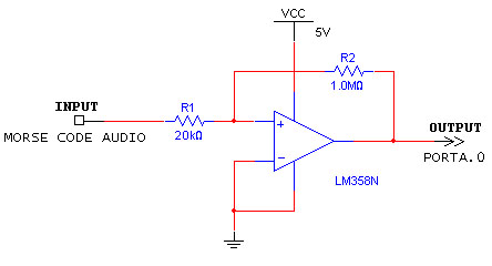
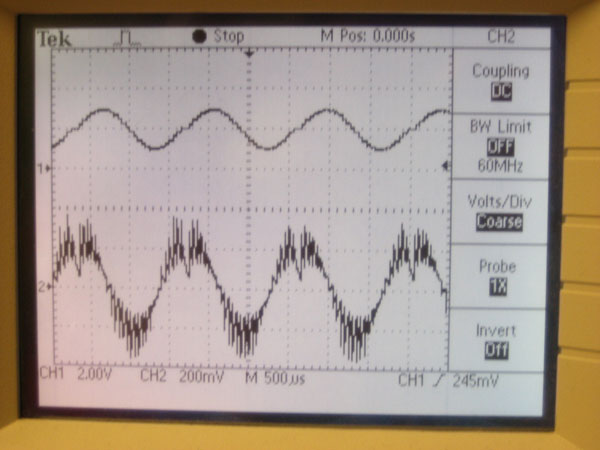
The result of using the Schmidt Trigger is that we obtained a 57% duty cycle square wave (600us LOW, 800us HIGH) whenever a 750 Hz sine wave (representing Morse Code audio) was present at the input terminal (see Figure 2). The output from the Schmidt Trigger was connected to PORTA.0 on the MCU so that the Mega32's internal ADC could be used to decode the waveform. We set the ADC to run at a speed of 2MHz (by setting the prescalar to 011) so that it would be fast enough to accurately read the waveform.
Figure 2. Waveforms of AC-coupled input from Parallel D/A (top) and Schmidt Trigger Output (bottom).
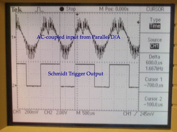
We only know that audio is present on the input whenever the Schmidt Trigger output goes LOW; however, since it is only in this state for a brief 600us for every period, choosing the right sampling frequency was crucial for attaining an accurate detection system. Originally, we decided to sample the waveform at 5kHz so that when we sampled two consecutive LOW values (this provided more accuracy than if we had just determined the value based on one sample), then we would know that we had a signal. Since this required the Timer ISR to run every 200us, we decided on an alternate method--to detect falling and rising edges. This allowed us to run the Timer ISR at 2kHz so that we could sample the waveform every 500us. The duration for which the signal is LOW is 600us; thus, we ensure that we will detect it at least once by sampling every 500us. If we had sampled every 600us, we would have risked missing the LOW peaks altogether. Every time a sample is taken, a flag, blipready, is asserted so that the "blip detection" state machine could be run.
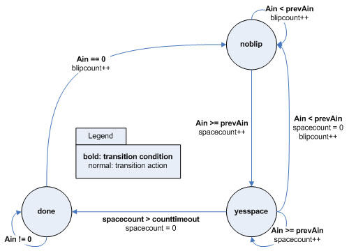
Figure 3 depicts the state machine embedded in the detect_blip() function that was used to decipher a dot from a dash and a short gap from a long one. The state machine is initialized to the "done" state, where it waits for the A/D input, Ain, to be 0, indicating that there is a signal. When this condition is met, the state machine transitions to the "noblip" state. In this state, if the current Ain is less than the previous Ain, prevAin (that is set to the current Ain at the end of the function), then the blipcount variable is incremented; otherwise, the state machine transitions to the "yesspace" state and increments spacecount. The purpose of the using the less-than operator is that if the current input is less than the previous input, then we know that a falling edge has been encountered. On the other hand if the current input is greater than or equal to the previous one, then we know that it is either staying steady or a rising edge has been encountered. The state machine stays in the "yesspace" state until another falling edge is encountered, at which point it transitions back to the "noblip" state.
However, several things can happen before this last condition is met. Each iteration in this state, the spacecount variable is incremented. If it reaches the point such that spacecount is greater than 10, which means that it is not just a HIGH peak (interspersed among LOW peaks), and blipcount is greater than at least the threshold for a dot, then the variable l_ready is asserted to allow the Morse Tree spanning state machine and blip is assigned either a value of 0 (for dot) or 1 (for dash). The value of blipcount must be above a certain threshold for a dot and another for a dash; these values were determined by dividing the durations for dots and dashes for each WPM (Table 1) by the period of the square wave (1.4ms). For example, to detect a 20 WPM dot, the blipcount would have to be above 25, and it would have to be above 125 for a dash. These values are not exactly 60/1.4 or 180/1.4, respectively; the reason for this is to account for the human error in measuring the durations and in the event of fluctuations in the signal. Furthermore, the spacecount can also lead to two different outcomes. Unlike the blipcount threshold, the spacecount threshold is determined by dividing the durations found in Table 1 by 0.5 (since the function is run every 500us). If the spacecount is above for the threshold for a inter-character gap, short gap or long gap, s_ready is asserted to allow Morse Tree spanning state machine to be run, and the variable space is set accordingly. The other possibility is that the spacecount exceeds even the threshold for a long gap; when this happens, the state machine transitions to the "done" state, s_ready is asserted and space is assigned 2 (for word). This condition indicates that the end of the transmission has been reached.
Figure 3. Blip detection state machine.
Once we had determined whether the input was a dot or a dash, we set out to decode the message. After considering several options, we decided that a Finite State Machine realized in a switch-case statement would give us the best results. There are several ways to use an FSM to decode Morse, and we decided to go with a binary tree traversal. One can build a Morse binary tree (like the one below) out where inputs are dots and dashes and the states are the letters, numbers, and punctuation marks.
Figure 4. Morse Code binary tree. (Adapted from Wikipedia)
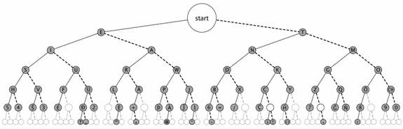
The FSM that traverses this tree based on the input is in the MorseChar() function. Every time a new word is being decoded, the state is set to Start. For example, if a dot is processed, the state moves to the letter ‘E’. If the next entry is a dot, then the machine moves the ‘I’ state. However, if a dash is processed, then we move right on the tree to ‘A’. On the other hand if a “space” is the next input (denoted as a multiple of dot – 3 between letters and 5 between words), the letter A is returned. The tree is traversed in a similar fashion for every message.
After the letters are determined and the variable space indicates that the end of the word has been reached, the characters were outputted to Hyperterm. To accomplish this task, we used the Serial ISR code from the Security System Lab so that the output to Hyperterm would not be blocking. It is important that the output not be blocking because our system is real-time. If the printing were blocking, we risked missing parts of incoming signals and thus outputting incorrect characters. This became a problem when we implemented speech because reading from flash is a blocking function call.
Morse Code Synthesis
We used a scheme very similar to that of the Cricket Call lab to generate our sine waves for Morse Code output. However, rather than using the PWM, which proved to be too noisy for our purposes, we took at approach used by Jeff Ting and Jinu Rhee for their Spring 2002 ECE 476 final project (a music synthesizer). Using the MATLAB code that they used, we generated a table of sine values and stored it into flash memory. We tried several different sampling frequencies ranging from 10kHz to 50kHz and determined that a sampling frequency of 20kHz was suitable for our needs. The reason that we wanted a clean signal is that we planned to test our entire system by using the Morse Code Synthesis output as the input of the Morse Code Processing unit.
In order to receive the text from the keyboard, we also used the Serial ISR. Again, this was essential to the functionality of our system because it was not blocking.
In the Timer ISR, we put the values for the sine waves onto PORTC when we wanted to output a signal, and we set PORTC to 128 (approximately halfway between 0 and 255) whenever we wanted to output nothing. Using this configuration allowed AC coupling to output a 0-centered sine wave. It was a bit tricky to implement both dots and dashes, basing the code on the Cricket Call lab so we made some modifications. In a 2-dimensional array, we stored a string of characters to represent each letter. The rows of the 2-dimensional array respresent the encoding and the columns represent the different characters to be outputted. The method was used to encode the words is to represent each dot with "10" and each dash with "1110". So, to encode the character 'A', we set the string to "101110" for dot, dash. A 0 is appended to each dot and dash to represent the inter-character gaps between the dots and dashes. When outputting the sine wave, rampup only occurs at beginning of the string and after a 0 has been seen. Additionally, rampdown only occurs when the next bit in line is a 0. For example, for the character 'A', would ramp up at the beginning, output, rampdown before the first 0 is reached, silence, ramp up, output and finally rampdown before the second 0 is reached. Before traversing to the next column of the array, a silence period representing that of a short gap is outputted. Moreover, to represent the end of a word, a string of "00000" was added to the buffer. When this is seen, a silence period representing that of a long gap is outputted.
Since we did not use the PWM for DDS, we had to build a R-2R DAC to convert the 8-bits on PORTC to an analog signal. We followed the instructions on Professor Bruce Land's website to build this. Ideally, the ratio of the "2R" and the "R" resistors would be exactly 2, but since 1% resistors are expensive and 5% resistors are not accurate enough, we chose to go with a 20K and a 10K resistor pack. Although the resistor packs are still only 5% accurate, the resistors on a single resistor pack are within 1% of one another. This gives us 7 bits of accuracy, which is sufficient for our purposes. We also built a voltage follower because when we fed the Morse Code output back into the Morse Code processing unit, we would not have a load resistance of 1Mohm. We then AC-coupled the output of the voltage follower so that the signal would centered around 0V and thus be able to trigger the Schmidt Trigger. Refer to Figure 5 for our overall circuit--the DAC is highlighted in blue and the voltage follower with AC coupler is highlighted in green.
Figure 5. Parallel DAC with AC-coupled voltage follower.
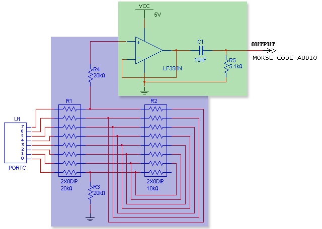
Figure 2 shows the waveform of the output of the AC coupler. Much of the noise on the signal is introduced by the AC coupling circuit. Figure 6 shows the input of the AC coupler and the resulting waveform.
Figure 6. Waveform out of the voltage follower (top) and out of the AC coupler (bottom).
Morse to Speech Synthesis
As an added functionality to our project, we decided to implement a speech synthesis component to our design. In essence, as Morse code is being inputted, not only would we translate the messages into text that is echoed on HyperTerm, but our design would also speak the words that are translated. We thought that this feature would not only add a human component to the design, but also make it easier for blind people to be able to learn Morse code.
There are many integrated circuits on the internet that will do this automatically, but with the cheapest being $80, it was beyond our budget constraints. There are several ways to implement speech on the ATMEL Mega32 chip, as outlined by Prof. Bruce Land. Ideally, we want our program to be robust that any messages can be decoded. The best method to accomplish this would be to use an allophone table, and design a state machine that will string together allophones depending on the letters’ positioning within the word and with respect to other letters. Thus we set off on exploring ways to emulate the PICtalker system, based on the now-obsolete SPO256-AL2 chip, which stored the allophone table as well as synthesized spoken words. Thanks to Prof. Land, who extracted the allophone table from the chip, we were able to play around with constructing words ourselves. The file contained raw audio which would save the hassle of recording, compressing and then decompressing our own audio.
After several days, we had constructed a moderately complex state machine to construct the words. However, we were not able to make any coherent words using the allophones. Thus we decided to scrap this method and explore a different route. Although, not as robust as the PICtalker system, we decided to use Differential, Pulse-Code Modulation, or DPCM. This would require us to prerecord words, compress, and then decompress the waveforms at 8kHz. For our purposes, we decided to record the top 100 most common words in the English language (in addition to a select others) using AT&T’s text-to-speech software. After each word was recorded as a .wav file, we used MATLAB and routines provided by Prof. Land to downsample the audio to 8kHz and compress them. The compressed audio was then included in header files in our C program. During operation, the resynthesis of the wave-files would be accomplished on the fly depending on the word that was typed. The output would then be given to the PWM, which is running at 7812 samples/sec, very close to 8kHz.
Since the output of the PWM is coming from PORTB.3, we needed some sort of low-pass filter to eliminate all extra noise. We experimented with several different setups, including an active, two-pole Chebychev Filter (Figure 7), with a frequency cut-off of 4Hz. However, this did not prove to be any better than a simple passive filter using a 2K resistor and a 1.1uF capacitance.
Figure 7. Two-pole Chebychev Filter.
One of the problems associated with our speech implementation is that header files are quite big (5Kbytes each). And since we are implementing a little more than 100 words, that requires a minimum memory of 500KB, way outside the range of the Flash memory already on the Mega32. This required us to look into an external DataFlash module on which to store and read the header files. Upon some research, we found that an ECE 476 group in 2004, Big Red Map had successfully used the Atmel AT45D021A DataFlash chip already located on some STK-500 boards. This chip has 2Mbits of memory, split up into 1024 pages of 264 bytes each, as well as 2 264 SRAM buffers for speedy writes and reads. The chip also supports Serial Peripheral Interface, or SPI, which would make it easy to use with the Mega32. Using the SPI driver, dflash.c, provided by ATMEL for this chip, we were able to successfully read and write to the chip. We decided to truncate our wave-forms to a uniform sized array of 528 bytes. This then allowed for easy allocation within the chip, where each word was split across two pages. For example, the word "about" would be stored in pages 0 and 1, while the next word "all" is stored in pages 2 and 3.
Figure 8. Block diagram of dataflash.
Before running our main program, we would store all the words on the chip. Then during main program operation, depending, on the word that was decoded, a state machine (located in SpeechWord) would decide which two pages to read from and give to the PWM. The first step to reading from the flash was to lead the desired pages into the the two buffers. When we tried to store to the buffers one after the other without delays, the program stalled. In the end, we discovered that the minimum delay is 75us. We used a for-loop to then read the compressed audio from the buffers and store it into the array that would be used by the PWM. Including this code into our base code (with the Morse Code processing and synthesis code), we ran into the problem of delays. Because reading from the buffers is a blocking function, the system would miss the first mark (dot or dash) of the next character. We realized that the problem was that our thresholds for detecting words and timeouts was too strict; thus there was a lot of time wasted from the time of the Morse Code is outputted and the time the system detects that a word was finished. Decreasing these thresholds such that it would still accurately interpret the Morse Code without the memory code freed up enough cycles to properly read from the buffers to achieve speech.
Another important thing to note is that for smooth operation, we needed to use two timers, T0 and T2. T0 was set to Overflow for PWM operation, and T2 was set to Compare Match for interfacing with HyperTerm.
Results
[ speed of execution ][ accuracy ][ safety & interference ][ usability ]
Speed of Execution
One of the most important parts of our project was the speed at which encoding/translation was done. Morse code is a Real-Time system, and as such, there cannot be much delay between input and output. After testing our system with multiple Morse messages, we found that it was very quick and had delays only on the order of 500us. We were very pleased with this result as it was one of the main challenges of this project.
Accuracy
Our system was also able to output clean Morse Code. After trying PWM and not being satisfied with the noisy output, we switched to a Parallel D/A approach for generating the Morse sine waves. Once this was done, we were able to generate much cleaner tones and were satisfied with the result.
Safety & Interference
Throughout the design stage, we made sure to consider safety. We have a very optimized circuit, with no overflowing wires that may be unsafe. We also made sure to use safety equipment (eye goggles) while using the soldering station. An indirect result of this is that our circuit has minimized interference and no RF noise with respect to other nearby circuits. However, we recognize that Morse code can get annoying to the untrained ear at high volumes; thus, we tried to kept the volumes at a minimum.
Usability
Our circuit uses general components (keyboards and speakers), making it usable by almost anybody. Furthermore, to improve usability of the text to Morse Code unit, we implemented such that Morse Code would only be outputted when the user hit the spacebar or the return key. This is to ensure that people of all WPM capabilities will be able to use our system without having their inputs butchered and consequently miscontrued.
Conclusion
Our design embodies the concepts in ECE 476. It combines many of the components of microcontroller design as well as:
- RS-232 serial interface with Hyperterm
- Digital Signal Processing
- Parallel Digital-to-Analog Converter
- SPI protocol (to communicate with Dataflash)
- DCPM Speech Synthesis
We were thus very happy to see that we were able to integrate all these parts to work together in unison without conflict.
Our Project & IEEE Code of Ethics (some don't apply)
- To accept responsibility in making decisions consistent with the safety, health and welfare of the public, and to disclose promptly factors that might endanger the public or the environment;
Since our product is intended for use by the public, safety was our first and foremost priority. For the Morse-to-Text-to-Speech component, there is no harm possible for the user. Since they will use a traditional Morse code clicker (NOT INCLUDED in our system) and our system is purely a translator, the only interface with our system and the user is the computer screen/speaker, which present no harm. The same applies for the Text-to-Morse end, as only a keyboard and a speaker are used.
- To avoid real or perceived conflicts of interest whenever possible, and to disclose them to affected parties when they do exist;
- To be honest and realistic in stating claims or estimates based on available data;
All data and results presented here are authentic. We tried our best to document the results (see pictures and schematics). People (Bruce Land, TAs, other students) who have seen our project in operation can also support our claims.
- To reject bribery in all its forms;
This design is also free under the Public License, as long as we are cited as the original designers. As such, we do not seek to gain anything from this project, as no bribery was given or accepted by us. This is purely a hobbyist project.
- To improve the understanding of technology, its appropriate application, and potential consequences;
This part of the code of ethics is foundation for our motivation behind this project. We had an interest in the use of Morse code in today’s society to help the disabled.
- To maintain and improve our technical competence and to undertake technological tasks for others only if qualified by training or experience, or after full disclosure of pertinent limitations;
- To seek, accept, and offer honest criticism of technical work, to acknowledge and correct errors, and to credit properly the contributions of others;
All software and hardware was constructed by us. We consulted several places for help in our design (Bruce Land, previous ECE 476 project). We made sure to credit all those whose work we referenced or used.
- To treat fairly all persons regardless of such factors as race, religion, gender, disability, age, or national origin;
Our project does not discriminate between its users. It is aimed towards English-speaking countries, but because of the ease of creating our own waveforms, any words in any language can be recorded and used.
- To avoid injuring others, their property, reputation, or employment by false or malicious action;
No data on this website is falsified.
- To assist colleagues and co-workers in their professional development and to support them in following this code of ethics.
We encourage every engineer (and non-engineer) to carry out their lives by a code of ethics and adhere to that code in everyday decisions.
Appendix A: Commented Code Listing
This zip file contains the 105 different English words (plus 1 for silence) that we encoded and stored onto the dataflash. Each compressed word is in a separate header file to be used in conjunction with the StoreFlash code.
This code was used to store the compressed audio onto the dataflash. Since only approximately 50 of the header files can be stored per flash of the MCU, this process has to be done iteratively for more words. (Note: If you cannot view this file on your browser, save the file to your computer and open it with your favorite word processing application, preferably a C-language IDE.)
This is the heart and soul of our project, all 2697 lines!
These helper files helped us tremendously. They have functions written by ATMEL Norway that interfaces the Mega32 with the dataflash located on some of the STK-500 boards--the exact product number is shown in our cost details below (Appendix C). Thanks ATMEL Norway for these wonderful functions!
Appendix B: Pictures
Figure 9. Project setup.
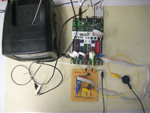
Figure 10. Project setup (up close).
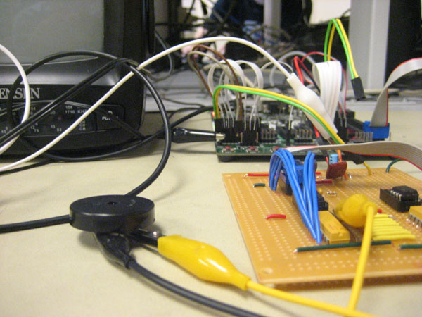
Figure 11. Wired up STK-500 development board with Mega32 MCU.
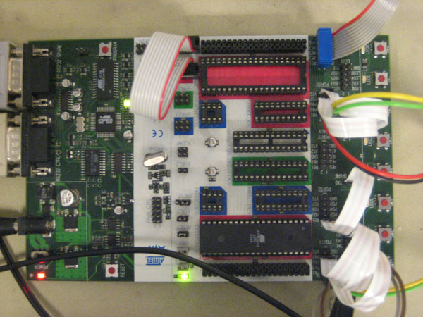
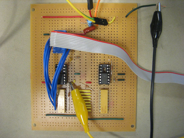
Figure 12. Auxiliary circuitry.
Appendix C: Cost Details
| Component | Cost/Item | Quantity | Cost |
|---|---|---|---|
| STK-500 Development Board | $15.00 | 1 | $15.00 |
| AT45D021A-RC Dataflash | Free (already on STK-500) | 1 | 0.00 |
| 6" Solder Board | $2.50 | 1 | 2.50 |
| Power Supply for STK-500 | $5.00 | 1 | 5.00 |
| B/W TV | $5.00 | 1 | 5.00 |
| 2-pin Flat Jumper Cables | Free (courtesy of the lab) | 9 | 0.00 |
| DIP Sockets | $0.50 | 3 | 1.50 |
| Headphone Jack & Speaker | Free (salvaged) | 1 | 0.00 |
| Piezo Speaker | $1.00 | 1 | 1.00 |
| Resistors & Resistor Packs (Assorted) | Free (courtesy of the lab) | 7 | 0.00 |
| Capacitors (Assorted) | Free (courtesy of the lab) | 3 | 0.00 |
| Op-amps (LM358N) | Free (courtesy of the lab) | 3 | 0.00 |
| Total | $30.00 | ||
We stayed well below the budget of the project by choosing to use solder boards instead of solderless protoboards and by making use of the components available to us in the lab and from past projects.
Appendix D: Specific Tasks
Michael Cen:
- Translation from audio to digital “dots” and “dashes”
- Morse Code encoding from typed letter, numbers, and punctuation
- Timing control between components
- Hardware setup
- Debugging
- Website
Mina Ghobrial:
- Morse Code decoding from dots and dashes to letters, numbers, and punctuation
- Speech Synthesis (recording, compression, decompression)
- DataFlash interfacing through SPI
- Debugging
Appendix E: References
- Wikipedia's Morse Code Page
- Learn Morse Code
- ARRL Radio
- Mega32 A/D and D/A
- Speech Synthesis on Mega32
- AT&T’s text-to-speech recorder
- Big Red Map
- Digital Music Synthesizer
We would like to thank the following people and organizations, for their generous donations of hardware, software, resources and time. Without them, our project would not have been easy (or possible for that matter):
- ATMEL Corporation
- MAXIM/DALLAS Integrated Circuits
- HP InfoTech
- AT&T Text-To-Speech
- Cornell University, ECE Department
- Professor Bruce Land and all of the ECE 476 TA's
- Shirlyn Jean-Louis and Chethan Pandarinath, Big Red Map
- Jeff Ting and Jinu Rhee, Digital Music Synthesizer