FIREFLY SYNCHRONIZATION AND NONLINEAR BEHAVIOR SIMULATIONS ON A MICROCONTROLLER
Saranjit Kaur and Michelle Mellers
ECE 476 Microcontroller Design
Spring 2007 Final Project

Figure 1: Sketch of a firefly. ( www.learner.org)
Introduction
This project implements a 2D matrix of bidirectional LEDs to simulate how fireflies in a population synchronize their flashing.
Fireflies
are an extraordinary species of bioluminescent animals which are able to
synchronize the timing of their light emission within a flashing population. In
places such as
To implement these goals, we created a 2D matrix of 8 “fireflies”. Each firefly is represented by a node in the 2D grid, and a connection between any 2 nodes is represented by a pair of 2 LEDS: an “emmiter LED” and a “sensor LED”. The fireflies are able to concurrently communicate and sense the signals emanating from surrounding fireflies using a form of one-directional LED communication. Each firefly is equipped with a fixed number of emitter LEDs and a fixed number of sensor LEDS, depending on the position of the LED within the matrix. For simplicity, we assumed that the fireflies’ positioned were fixed in time, i.e. they were not able to travel. The firefly flashes using one set of LEDS, the emitter LEDs; the firefly senses the surrounding fireflies flash using another set of LEDs, the sensor LEDs. To accurately mimic the way fireflies in nature sense neighboring signals, we decided that the emitter LEDs must be electrically isolated from the sensor LEDS, i.e., communication from one firefly to another is done through optical signaling. Each firefly is equipped with an individual (i.e. independent) “brain” in the microcontroller code that processes the signals that it has sensed and tries to synchronize its own flashing with these surrounding fireflies. Like in any real world situation, each firefly flashes with a random frequency and phases and it adjusts these flashing parameters to conform to the overall flashing of the localized population.
High
Level Design
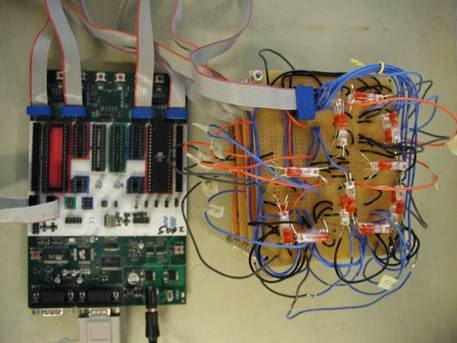
Figure 2: Image of the final project device, the STK500 development board and the Mega32 MCU.
Our
project idea came from Professor Steve Strogatz's
work in
The array above shows the 8 fireflies and each sensor LED with the corresponding pin number. The emitter LEDs are not shown above. A side view of the matrix shown in Figure 3.
Figure 4: A side view of the LED matrix.
The mathematical basis for the synchronization scheme in our 8-insect array is given directly below. The variable “xij” is defined as follows: “x” is the period of the flashing. “i” is the number label of the individual firefly. “j” is the iteration number.
One iteration of the mathematical algorithm applied to the 8-insect array:
x1n+1=(x2n + x4n)/2
x2n+1=(2x1n + x5n +x3n)/4
x3n+1=(x2n + x6n)/2
x4n+1=(2x1n + x5n +x7n)/4
x5n+1=(x2n + x4n +x6n+x8n)/4
x6n+1=(x3n + x5n)/2
x7n+1=(x4n + x8n)/2
x8n+1=(x5n + x7n)/2
Unfortunately, this synchronization scheme did not work successfully because of 2 reasons: First, we had to implement edge effects in the array. These undesirable effects resulted from the fireflies that had exactly three neighbors, an odd number. Each of these fireflies received 3 optical signals, added them together, and then added one more of the neighboring signals (repetition) so that the average could be calculated by taking this new sum and simply shifting right by 2 bits. We did not want to do any direct multiplication or division in the code since the computation time would increase greatly and slow down the code. A larger array of LEDs is better, because the edge effects will have a small (degrading) contribution to the overall system. However, even if we had used a much larger LED array, then this scheme of the averaging neighboring signals would only partially work, as will soon be discussed.
The second reason for non synchronization is that the method of averaging that we used to calculate the next state of the system created a nonlinear system. As we learned in ECE 320 and TAM 578, nonlinear systems are very difficult to solve. The most convenient method of solving nonlinear systems is to plot a “ x vs. x΄ ” graph, look for basins of attraction and then determine initial conditions for the system that will ultimately converge the system into one of the possible basins of attraction. Therefore, our system of 8-fireflies will not be able to completely synchronize because we essentially built a nonlinear system by using difference equations to compute the next iterative state of our system. However, there are ways to force this nonlinear behavior into a linear behavior to make the system converge, and one of the most convenient ways is to use a very small system containing only 2 or 3 fireflies.
For a very large number of nodes (fireflies), our system theoretically has 2 steady states: One state is where all of the LEDs are made to flash at the same frequency and phase, and the system always stays in this state. The other steady state is where alternatively placed fireflies flashing out of phase with the rest of the fireflies. For example, even number labeled fireflies would be made to flash exactly out of the phase with odd number labeled fireflies. If this device is working properly, then the even and odd fireflies will keep swapping their phases with one another. These particular steady states have certain implications for our device: First, there are only 2 basins of attraction for this system and these can be used as a proof of concept that can easily be implemented on our device. Second, neither of the steady states will result in the synchronized flashes.
Initially, the goal of this project was to simply mimic how fireflies flash in nature, but we have now developed our project into a physical investigation of how a nonlinear systems changes in response to an increasing number of nodes (in our case, fireflies).
One iteration of the mathematical algorithm applied to the 3-insect array:
x1n+1=(x2n + x6n)/2
x2n+1=(x1n + x2n)/2
x6n+1=(x1n + x6n)/2
Notice above that fireflies #2 and #6 add the one neighboring period with their own period before dividing by 2. Once again, we implement division using shift right commands with require an even number of arguments. This “self averager” technique slightly slows down the convergence time, but convergence is still guaranteed under this scheme to happen in 10 iterations.
Program/Hardware Design
Hardware
The Atmel AT90 Mega-32 MCU chip, an 8-bit microcontroller with programmable in-flash memory, was supported by a STK500 AVR® Flash MCU evaluation board. This board is essentially a development board complete with pushbuttons, LEDs, 4 ports, serial connections (programming and application), and a 16 MHz crystal. PORT A was connected to the emitter LEDs. PORTB, PORTC and PORTD were connected to the sensors LEDs via the 2X non-inverting operational amplifier and the Schmidt Trigger.
The schematic directly below (Figure 5) shows the hardware needed to generate the flashing by connecting the emitter LEDs to the MCU and ground.
The right hand side of Figure 5 shows the emitter LED of each firefly. The LED is tied directly to the output pins of the MCU, which are square-wave signals in our program. Connecting the emitter LEDs for the center firefly proved to be a little difficult, because for this LED a total of 4 emitter LEDs had to be connected to one i/o pin. The LEDs were connected in parallel; connecting the LEDs in series would only be able to successfully power 3 of the 4 LEDs connect 3 because they require at least 1.7V to turn on and 5V power supply can only accommodate three 1.7V drops in the voltage. In parallel, the LEDs are current-limited but this scheme allows for the 4 LEDs to be connected to one output i/o pin. No resistors were used because we wanted the emitter LEDs as bright as possible to be able to communicate with sensor LEDs. The current and voltage under this scheme agreed with values provided with the LED spec sheet, and they worked well as a result.
The schematic directly below (Figure 6) shows the hardware needed to receive the signal from the sensor LEDs and digitize it so that the MCU will be able to recognize it as valid logic values.
Our scheme for the sensor LEDs included an amplifier followed by a Schmidt trigger.

This circuit consists of a 2X non-inverting operation amplifier (simple negative-feedback with R1 and R2 at the same resistance) and a Schmidt Trigger circuit. Both the negative-feedback operational amplifier and the Schmidt Trigger were constructed from LM358 IC chips, which are not rail-to-rail operational amplifiers. The first stage of our hardware was a 2X non-inverting amplifier. The output of the sensor LED is feed into the positive input of the LM358 op amp connected in a negative feedback loop. The gain of a simple negative-feedback op amp circuit is calculated below:
Vout = Vin * ( 1 + R2/R1)
Gain = Vout / Vin = (1 + R2/R1)
Since R1 = R2, Gain = 2.
10 kΩ PACKAGED resistors with 1% accuracy were used for R1 and R2. We needed to amplify the signal coming out of the sensor LED, because LEDs can only serve as weak photodiodes. The signal emanating from the sensor LED had an amplitude of roughly 1.2V, and therefore, the output of the op amp was approximately at 2.5V. The signal then passes from the op amp to the Schmidt Trigger, where it can be converted to a digital signal for input into the MCU. Therefore, the Schmidt trigger acts as an A/D converter. We had it set to trigger at 2V, knowing that an ideal high signal coming into the trigger will be greater than 2V. Since the Schmidt trigger is not constructed from a rail-to-tail op amp, the output of the trigger had a true high logic signal but an ambiguous low logic signal. The code was not able to recognize the following statement: “arg1 == 0”. According to Horowitz and Hill in The Art of Electronics the LM358 uses a PNP follower to ground “which can only pull down to within a diode drop of ground” (229). Therefore, it makes sense that the lowest voltage we could output from the trigger was 0.7V. Therefore, a comparison with 1 is done by either writing “arg1 == 1” or “arg 1 =~ 1”. The end of the two stages produces a reasonable digital signal, with a small but manageable amount of superimposed noise. We tested these circuits first on a breadboard, and this can be seen in Figure 7.
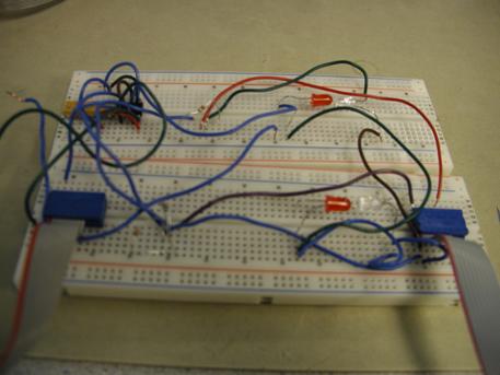
Figure 8: Protoboard version of our sensor circuit.
Our LED communication was based mainly on proximity. It worked well when the two LEDs were in the same plane and directly facing each other, as can be seen in Figures 2, 3, and 4. If the LEDs were not in the same plane but were instead at an angle, the signal would drop off exponentially until there was essentially no signal at an angle above 10 degrees separation. By trial and error, we were able to determine that the red and clear LEDs worked equally well as emitters compared to the yellow and green ones. The red LEDs worked better as receivers. This might be due to the fact that the red epoxy could amplify the red signal more than the other light sources. Therefore, we tested the one-directional LED communication with a clear LED serving as the emitter and a red LED serving as the sensor. The signal received by the sensor LED was fairly clean (minimal noise) and therefore neither analog nor digital filtering was included.
We ran into several problems when we tried to duplicate the circuit. From Lab 1, we knew that the STK500 could only handle 10 LEDs lit off of it. However, we attached 20 LEDs to the development board in this project. The LEDs would flash 2 to 3 times before the MCU chip was completely turned off (automatic chip safety routine kicked in when we tried to draw too much power to the LEDs). It took us a while to realize that the STK500 couldn’t provide enough power, because we initially suspected that our device has a short somewhere in the wiring. Once we realized it was a case of insufficient power, we connected an additional 5 V power supply the STK500 to power up all of the LEDs. The Proto-board PB-503 served easily as the 5 V power supply. We connected the ground pin to the ground on the proto-board and the Vcc to the 5V power supply on the proto-board. Once the power issue was solved, the circuits were all soldered onto PCB boards and stacked them into a cube to minimize the dimensions of the device.
Software
Our software design was based on the scheme outlined in the high level design, in which we used an averaging algorithm to try to synchronize the flashing. Our main concern with the code was trying to minimize the number of variables and/or length of the code that we used and to try and keep our computation as simple as possible. To keep the computation simple, we only divided by 2 and 4 so that shift right commands would always be applicable to the computation.
The flashing of each LED was done using a counter and if statements. During the first part of the count the LED would be assigned high and during the latter part of the count it would be off. This count is the same for each LED; each LED is on for 5 counts and off for 5. It then resets itself. The rate at which the count is done is what changes for each of the LEDs. This is set randomly in the initialize function. This flash continues throughout the calculations and only gets reset when the calculations are done to restart the phase.
This section aims to do the following: explain the reasoning behind the design of the state machine and tasks that comprise our overall program. This will be done by outlining the function of each state/task and how it contributes to the overall program. (The sections following this one will cover the debugging and testing of the code.)
C Libraries:
The following libraries were included: Mega32.h, stdio.h, stdlib.h, and string.h.
“Interrupt” Function:
Only one hardware interrupt were used in this program: The Timer 0 Compare Match interrupt was used to decrement the counters used as counters to get the emitter LEDs to flash at their appropriate frequencies. It is also used to increment “countdelay” variables used to time the period of the neighboring LEDs.
“Main” Function:
The “main” function first calls the “initialize” function. It first calls the 8 emitter LED functions “ledflash#()” from the timer set by the Timer0 compare match ISR. Then it calls the 8 sensor LED functions “updatfreq#()”. The “syncflash” function is called when the condition that all the fireflies (blocks) have figured out all the frequencies of their neighbors’ flashing.
“Initialize” Function:
Called from the “main” function, the “initialize” function does the following commands:
First, the data flow was set such that PORT A is an output (to get the emitter LEDs to flash). PORT B, PORTC and PORTD are inputs (to get the signal from the sensor LEDs and send it to the MCU for analysis), and PORT D is an output (for the ADC output). The Timer 0 Compare Match ISR is set to occur every 1 ms by setting the compare register to 249 and the prescalar to 64 and turning on the clear-on-match option. The LEDs are initialized off. Default states for switch statements, timers, flags and global variables are set to initial values. The timers for the “ledflash#()” functions are set to random integers by calling the “rand()” macro. This was done to generate 8 different frequencies for the 8 different blocks of emitter LEDs. Last, global interrupts are enabled using the assembly language command “sei”.
The “Ledflash#” Function:
The 8 “Ledflash#” functions are called directly from the “Main” function via the Timer0 compare match interrupt. Its timer is reset at the beginning of the code. Then the LED is turned on for first 5 counts (5 * 1 ms * the random period of flashing), and LED is turned off for the rest of the random period.
“Updatefreq#”and “SyncFlash” Functions:
The 8 “Updatefreq#” functions are called directly from the “Main” function via the Timer0 compare match interrupt. Its timer is reset at the beginning of the code. The function is comprised of a switch statement for each neighbor LED, and the switch statement was written to evaluate the period at which the neighbor LED flashes. Once all the neighbors have been evaluated exactly once, them the periods of the neighboring flashes are averaged, and a buffer variable “timebuff#” will be set to this average value. Once all the fireflies have successfully evaluated their neighbors, then the “syncflash” function will be called to simultaneously update the periods of the flashing emitting LEDs. Notice that the emitter LEDs are updated simultaneously; this is done to set all the phases to zero, and therefore, the phases of the flashing will not have to be tediously computed by the microcontroller.
Figure 9: State machine used in the function “Ledflash#()”.
Debugging the Hardware and Code:
We looked at ordering multiplexers to connect the 24 sensors LEDs to the 8 A/D converters provided on the Mega32 chip. However, we decided to build 20 analog 1-bit A/D converters out of Schmidt Triggers, which were made out of LM358s available in lab. This allowed us to run 20 analog-to-digital conversions simultaneously, while the ADC on the Mega32 would only have allowed us to collect 8 bits at one time. We built and tested the sensor hardware circuits first on a protoboard and then soldered them to PCBs. The other significantly difficulty with the code was determining how to write code for our non-ideal signals, where the analog low wasn’t equivalent to a logic zero (+ 0.7V). The LM358 op amps were not rail-to-rail, and this affected the output of our ADC, because the low signal was at 0.7 V. We circumvented this problem by writing all the logical comparisons with reference to 1s and not 0s.
We first tested the software for a small array shown in Figure 4, a 3-insect array. We started with a small array of fireflies to if the code could converge for small system of fireflies (nodes), and then we increased the number of fireflies to 4, and then to 8. Our first hurdle writing the code dealt with getting the emitter LEDs top flash randomly. It was relatively easy to make the emitter LEDs flash with different frequencies, and this is what we ended up implementing for the final project. However, getting random phases proved to be much more difficult. We were able to implement delay_us() macros to get the phase delays, but we were unable to vary the order in which the LEDs would flash. But for all intensive purposes in this project, using solely random periods creates a sufficiently random initial state for the system.
Results
and Conclusions
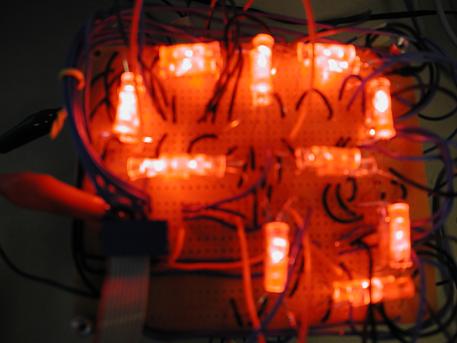
Figure 10: Image of device in action. Fireflies are represented by the junctions in between the LEDs.
To demo the functionality of the project, we decided to build a 3-insect array and show that the hardware and software work together to synchronize this simple system. The averaging scheme does in fact work for a system with only 3 entities, as it successfully converged all 3 fireflies on the device. In the Introduction, we gave an informal discussion as to why our scheme to average the frequencies of neighboring fireflies essentially creates a nonlinear system. This is certainly true for systems containing 4 or more LEDs in the system, but systems containing 3 or less groups of LEDs are simple linear system. These 3 groups of LEDs converged, while none of the groups of LEDs converted for systems with 4 or more groups of LEDs. The results of our 8-insect array show that the solution of the system did not converge to one single frequency and phase. The LEDs never managed to synchronize, and this confirms Prof. Strogatz’s academic work that a nonlinear system such as this will not synchronize its flashes. To synchronize the LEDs we need to find the initial conditions that would end in synchronization. Unfortunately, in our project we were unable to find these values. Parts of the matrix would appear to synchronize when we ran the code for long enough, but they would eventually fall out of synchrony. The one condition we were able to test to see if all the LEDs were flashing if they would stay flashing. The matrix did in fact do this. Had we developed a larger matrix, we might have been able to see distinct sections of the LEDs synchronize, a phenomenon which is characteristic to large systems in some nonlinear systems.
Though our project ran into complications with the synchronization scheme, we were able to build a LED-based device and microcontroller code which can be easily modified to run difference equations and be able to physically observe other types of nonlinear systems. Future development of this project would be especially practical for visualization of nonlinear behavior and ad hoc networks.
Suggestions for Future Work
In hindsight, there are parts of this project which could have been improved to give better experimental results. The first suggestion for any future work on project is to minimize the edge-effect in small systems by setting any extra term needed to average the frequencies using a neighbor on the other side of the board. Essentially, use the microcontroller code to “wrap” the signal around to other side of the board if an extra term is needed. The second suggestion is to use the ADC converters on the Mega32 instead of building analog ADCs, and if ADCs must be built, double check to make sure that the operational amplifiers can provide a rail-to-rail output. If more i/o ports can be connected to the microcontroller chip, then do everything possible to extend the 2D matrix of LEDs so that the nonlinear behavior might be able show partial linearity in larger systems.
Price List
|
Part |
Qty |
Price |
Total
Cost |
|
PCB
Board |
4 |
$2.50 |
$
10.00 |
|
STK500 |
1 |
$15.00 |
$
15.00 |
|
LED |
40 |
$0.50 |
$
20.00 |
|
LM358 |
20 |
$0.12 |
$
2.40 |
|
|
|
|
|
|
TOTAL |
|
|
$
47.40 |
Legal Considerations
In this project, we built on conceptual landmarks made by Dietz, Yerazunis and Leigh for LED communication and Mirollo and Strogatz for nonlinear system behavior. However, we independently built the hardware and wrote the software using the basic ECE knowledge from classes taken at Cornell Univeristy. We did not use code from the public domain. Literature sources were referenced either in body of the document or listed in the References section. There will be no issues of Intellectual Property or Patent/Tradement infringements, as we strictly followed IEEE’s Code of Ethics.
Safety Design Standards
Since our project only involved standard resistors, connector and IC parts (LM358), we did not have to design our hardware around safety considerations other than insulation around all wires, especially wires connecting directly to power and ground. We also did not design a consumer product so we did not have to worry about shock, etc.
IEEE Code of Ethics
We conscientiously followed the IEEE Code of Ethics throughout development of this final project. We made responsible decisions when working in the laboratory to turn off power supplies, soldering irons, and any other electrical appliances when not in use. This shows our regard for our own safety and for the safety of our peers. We avoided conflicts of interest by volunteering to leave lab stations if someone belonging to the particular lab session was unable to find a spot. We spent our time in lab as efficiently as possible to avoid wasting lab space. We made honest attempts at debugging our code before seeking a TA for assistance, and we did our best not to take up too much of the TAs’ time to allow other students to get needed help. We left our lab space clean and put away all lab supplies and equipment that we used. We meticulously credited the work of others that we used in our project, and made a note of crediting in the most minor of contributions. We presented our experimental results as accurately as possible, and did not try to fix our data to meet initially specified goals. We hope that the work we done in this final project may assist students to continue this project and improve our understanding of nonlinear system behavior and ways to physically simulate them.
References
We would like to thank
Data Sheet:
Papers:
Previous 476 Project referenced:
SecureLED: Better Access Control
Final Project Code:
// CORNELL ECE 476 Final Project
// Spring 2007
// Date of Last Modification: 4/30/07 morning
// Saranjit Kaur, sk398
// Michelle Mellers, msm39
//********************************************************************************
// Declarations, Instantiations and Initializations:
#include <Mega32.h>
#include <stdio.h>
#include <stdlib.h> // for rand()
#include <delay.h>
#include <math.h>
#define begin {
#define end }
#define t0 500 // 500 ms
#define t1 500 // updatefreq fncn timer
#define st10a 1
#define st10b 1
#define st11a 2
#define st11b 2
#define reset1a 3
#define reset1b 3
#define st21a 1
#define st21b 1
#define st21c 1
#define st20a 2
#define st20b 2
#define st20c 2
#define reset2a 3
#define reset2b 3
#define reset2c 3
#define st31a 1
#define st31b 1
#define st30a 2
#define st30b 2
#define reset3a 3
#define reset3b 3
#define st41a 1
#define st41b 1
#define st40a 2
#define st40b 2
#define reset4a 3
#define reset4b 3
#define st51a 1
#define st51b 1
#define st51c 1
#define st51d 1
#define st50a 2
#define st50b 2
#define st50c 2
#define st50d 2
#define reset5a 3
#define reset5b 3
#define reset5c 3
#define reset5d 3
#define st61a 1
#define st61b 1
#define st61c 1
#define st60a 2
#define st60b 2
#define st60c 2
#define reset6a 3
#define reset6b 3
#define reset6c 3
#define st71a 1
#define st71b 1
#define st70a 2
#define st70b 2
#define reset7a 3
#define reset7b 3
#define st81a 1
#define st81b 1
#define st80a 2
#define st80b 2
#define reset8a 3
#define reset8b 3
void initialize(void);
void main(void);
void ledflash1(void); // flash LEDS on blocks 1 & 9
void ledflash2(void);
void ledflash3(void);
void ledflash4(void);
void ledflash5(void);
//void ledflash6(void);
void ledflash7(void);
//void ledflash8(void);
void updatefreq1(void);
void updatefreq2(void);
void updatefreq3(void);
void updatefreq4(void);
void updatefreq5(void);
void updatefreq6(void);
//void updatefreq7(void);
//void updatefreq8(void);
void syncflash(void);
//void puts_int(void);
//char led;
char count1a, count1b, count2a, count2b, count2c, count3a, count3b, count4a, count4b, count5a, count5b, count5c, count5d, count6a, count6b, count6c, count7a, count7b, count8a, count8b;
int p1a, p1b, p2a, p2b, p2c, p3a, p3b, p4a, p4b, p5a, p5b, p5c, p5d, p6a, p6b, p6c, p7a, p7b, p8a, p8b;
int cntlst1a, cntlst1b, cntlst2a, cntlst2b, cntlst2c, cntlst3a, cntlst3b, cntlst4a, cntlst4b, cntlst5a, cntlst5b, cntlst5c, cntlst5d, cntlst6a, cntlst6b, cntlst6c, cntlst7a, cntlst7b, cntlst8a, cntlst8b;
char timebuff1, timebuff2, timebuff3, timebuff4, timebuff5, timebuff6, timebuff7, timebuff8;
char timebufflast1, timebufflast2, timebufflast3, timebufflast4, timebufflast5, timebufflast6, timebufflast7, timebufflast8;
int countdelay1, countdelay2, countdelay3, countdelay4, countdelay5, countdelay6, countdelay7, countdelay8;
char time1reset, time2reset, time3reset, time4reset, time5reset, time6reset, time7reset, time8reset;
char time1, time2, time3, time4, time5, time6, time7, time8, time9, time10, time11, time12, time13, time14, time15, time16;
char ptime1a, ptime1b, ptime2a, ptime2b, ptime2c, ptime3a, ptime3b, ptime4a, ptime4b, ptime5a, ptime5b, ptime5c, ptime5d, ptime6a, ptime6b, ptime6c, ptime7a, ptime7b, ptime8a, ptime8b;
int blockready[20];
char durationcounter1 = 0;
char durationcounter2 = 0;
char durationcounter3 = 0;
char durationcounter4 = 0;
char durationcounter5 = 0;
char durationcounter6 = 0;
char durationcounter7 = 0;
char durationcounter8 = 0;
//char count1, count2a, count2b, count3a;
//char t1, t2a, t2b, t3a;
//TX empth ISR variables
// unsigned char t_index; //current string index
// unsigned char t_buffer[10]; //output string, originally was [16]!!!!!!!
// unsigned char t_ready; //flag for transmit done
// unsigned char t_char; //current character
//char led;
int randperiod2, randperiod3, randperiod4, randperiod5, randperiod6, randperiod7, randperiod8;
//********************************************************************************
interrupt [TIM0_COMP] void timer0_compare(void)
begin
if (time1reset>0) --time1reset;
if (time2reset>0) --time2reset;
if (time3reset>0) --time3reset;
if (time4reset>0) --time4reset;
if (time5reset>0) --time5reset;
//if (time6reset>0) --time6reset;
if (time7reset>0) --time7reset;
//if (time8reset>0) --time8reset;
if (time9>0) --time9;
if (time10>0) --time10;
if (time11>0) --time11;
if (time12>0) --time12;
if (time13>0) --time13;
if (time14>0) --time14;
//if (time15>0) --time15;
//if (time16>0) --time16;
countdelay1++;
countdelay2++;
countdelay3++;
countdelay4++;
countdelay5++;
countdelay6++;
//countdelay7++;
//countdelay8++;
end
//**********************************************************
// //UART xmit-empty ISR
// interrupt [USART_DRE] void uart_send(void)
// begin
// t_char = t_buffer[++t_index];
// if (t_char == 0)
// begin
// UCSRB.5=0; //kill isr
// t_ready=1; //transmit done
// end
// else UDR = t_char ; //send the char
// end
//********************************************************************************
void main(void)
begin
initialize(); // does this need to be at the top of the "main" function?
// printf("Time1: %d\n\r",randperiod2);
// printf("Time2: %d\n\r",randperiod3);
// printf("Time3: %d\n\r",randperiod4);
while(1)
begin
if (time1reset==0) ledflash1(); // flash LED1
if (time2reset==0) ledflash2(); // flash LED2
if (time3reset==0) ledflash3(); // flash LED3
if (time4reset==0) ledflash4(); // flash LED4
if (time5reset==0) ledflash5(); // flash LED5
//if (time6reset==0) ledflash6(); // flash LED6
if (time7reset==0) ledflash7(); // flash LED7
// if (time8reset==0) ledflash8(); // flash LED8
if (time9==0) updatefreq1();
if (time10==0) updatefreq2();
if (time11==0) updatefreq3();
if (time12==0) updatefreq4();
if (time13==0) updatefreq5();
if (time14==0) updatefreq6();
// if (time15==0) updatefreq7();
// if (time16==0) updatefreq8();
// if ((blockready[0] ==1 ) && (blockready[1] ==1 ) && (blockready[2] ==1 ) && (blockready[3] ==1 ) && (blockready[4]) && (blockready[5]) && (blockready[6]) && (blockready[7]) && (blockready[8]) && (blockready[9]) && (blockready[10]) && (blockready[11]) && (blockready[12]) && (blockready[13]) && (blockready[14]) && (blockready[15])) syncflash(); //&& (blockready[18]) && (blockready[19])) syncflash();
end // end the while(1) loop
end // end main function
//********************************************************************************
// FLASH LED 1
void ledflash1(void)
begin
time1reset = time1; // reset the timer for this function
if ((durationcounter1 > 5) && (durationcounter1 < 11)) // LED will be ON for a total of 5 ms
begin
PORTA.0 = 0;
durationcounter1++;
end
else if (durationcounter1 < 6)
begin
PORTA.0 = 1;
durationcounter1++;
end
else
begin
durationcounter1 = 0; // increment counter
//PORTB.0 = 1; // turn one
end
end // end the ledflash function
//********************************************************************************
// FLASH LED 2
void ledflash2(void)
begin
time2reset = time2; // reset the timer for this function
if ((durationcounter2 > 5) && (durationcounter2 < 11)) // LED will be ON for a total of 5 ms
begin
PORTA.1 = 0;
durationcounter2++;
end
else if (durationcounter2 < 6)
begin
PORTA.1 = 1;
durationcounter2++;
end
else
begin
durationcounter2 = 0; // increment counter
//PORTB.1 = 1; // turn one
end
end // end the ledflash function
//********************************************************************************
// FLASH LED 3
void ledflash3(void)
begin
time3reset = time3; // reset the timer for this function
if ((durationcounter3 > 5) && (durationcounter3 < 11)) // LED will be ON for a total of 5 ms
begin
PORTA.2 = 0;
durationcounter3++;
end
else if (durationcounter3 < 6)
begin
PORTA.2 = 1;
durationcounter3++;
end
else
begin
durationcounter3 = 0; // increment counter
//PORTB.2 = 1; // turn one
end
end // end the ledflash function
//********************************************************************************
// FLASH LED 4
void ledflash4(void)
begin
time4reset = time4; // reset the timer for this function
if ((durationcounter4 > 5) && (durationcounter4 < 11)) // LED will be ON for a total of 5 ms
begin
PORTA.3 = 0;
durationcounter4++;
end
else if (durationcounter4 < 6)
begin
PORTA.3 = 1;
durationcounter4++;
end
else
begin
durationcounter4 = 0; // increment counter
//PORTB.5 = 1; // turn one
end
end // end the ledflash function
//********************************************************************************
// FLASH LED 5
void ledflash5(void)
begin
time5reset = time5; // reset the timer for this function
if ((durationcounter5 > 5) && (durationcounter5 < 11)) // LED will be ON for a total of 5 ms
begin
PORTA.4 = 0;
durationcounter5++;
end
else if (durationcounter5 < 6)
begin
PORTA.4 = 1;
durationcounter5++;
end
else
begin
durationcounter5 = 0; // increment counter
//PORTB.4 = 1; // turn one
end
end // end the ledflash function
// //********************************************************************************
// // FLASH LED 6
// void ledflash6(void)
// begin
//
// time6reset = time6; // reset the timer for this function
//
//
// if ((durationcounter6 > 5) && (durationcounter6 < 11)) // LED will be ON for a total of 5 ms
// begin
// PORTA.5 = 0;
// durationcounter6++;
// end
// else if (durationcounter6 < 6)
// begin
// PORTA.5 = 1;
// durationcounter6++;
// end
// else
// begin
// durationcounter6 = 0; // increment counter
//
//PORTC.0 = 1; // turn one
//
// end
// end // end the ledflash function
//********************************************************************************
// FLASH LED 7
void ledflash7(void)
begin
time7reset = time7; // reset the timer for this function
//delay_ms(randphase7);
if ((durationcounter7 > 5) && (durationcounter7 < 11)) // LED will be ON for a total of 5 ms
begin
PORTA.6 = 0;
durationcounter7++;
end
else if (durationcounter7 < 6)
begin
PORTA.6 = 1;
durationcounter7++;
end
else
begin
durationcounter7 = 0; // increment counter
//PORTB.6 = 1; // turn one
end
end // end the ledflash function
// //********************************************************************************
// // // FLASH LED 8
//
// void ledflash8(void)
// begin
//
// time8reset = time8; // reset the timer for this function
//
// //delay_ms(randphase7);
// if ((durationcounter8 > 5) && (durationcounter8 < 11)) // LED will be ON for a total of 5 ms
// begin
// PORTA.7 = 0;
// durationcounter8++;
// end
// else if (durationcounter8 < 6)
// begin
// PORTA.7 = 1;
// durationcounter8++;
// end
// else
// begin
// durationcounter8 = 0; // increment counter
//
//PORTB.6 = 1; // turn one
//
// end
// end // end the ledflash function
//********************************************************************************
// EACH FIREFLY SENSES A NEARBY FLASH AND ADJUSTS THE FREQ OF ITS OWN FLASHING
// Block 1
void updatefreq1(void)
begin
time9 = t1; // reset the function timer
switch(count1a)
begin
case st11a:
if(PORTB.0==1)
begin
count1a = st11a;
p1a++;
end
if (PORTB.0 =~1)
begin
p1a++;
count1a = st10a;
end
break;
case st10a:
if(PORTB.0 =~ 1)
begin
count1a = st10a;
p1a++;
end
if (PORTB.0==1)
begin
ptime1a = p1a;
blockready[0] = 1;
count1a = reset1a;
end
break;
case reset1a:
p1a = 0;
if((blockready[0] == 0) && (PORTB.0 == 1) && (cntlst1a =~ 1)) // condition for the rising edge
begin
count1a = st11a;
p1a++;
end
else
begin
count1a = reset1a;
cntlst1a = PORTB.0;
p1a = 0; //new 2:35 pm
end
break;
end
switch(count1b)
begin
case st11a:
if(PORTB.1==1)
begin
count1b = st11b;
p1b++;
end
if (PORTB.1 =~1)
begin
p1b++;
count1b = st10b;
end
break;
case st10b:
if(PORTB.1 =~ 1)
begin
count1b = st10b;
p1b++;
end
if (PORTB.1==1)
begin
ptime1b = p1b;
blockready[1] = 1;
count1b = reset1b;
end
break;
case reset1b:
p1b = 0;
if((blockready[1] == 0) && (PORTB.1 == 1) && (cntlst1b =~ 1)) // condition for the rising edge
begin
count1b = st11b;
p1b++;
end
else
begin
count1b = reset1b;
cntlst1b = PORTB.1;
p1b = 0; //new 2:35 pm
end
break;
end
if ((blockready[0]==1) && (blockready[1]==1))
begin
timebufflast1 = timebuff1;
timebuff1 = (ptime1a + ptime1b) >> 1; // senses block 2 and itself
ptime1a = 0;
ptime1b = 0;
syncflash();
end
end // end the updatefreq function
//********************************************************************************
// EACH FIREFLY SENSES A NEARBY FLASH AND ADJUSTS THE FREQ OF ITS OWN FLASHING
// Block 2
void updatefreq2(void)
begin
time10 = t1; // reset the function timer
switch(count2a)
begin
case st21a:
if(PORTB.2==1)
begin
count2a = st21a;
p2a++;
end
if (PORTB.2 =~ 1)
begin
p2a++;
count2a = st20a;
end
break;
case st20a:
if(PORTB.2 =~ 1)
begin
count2a = st20a;
p2a++;
end
if (PORTB.2 == 1)
begin
ptime2a = p2a;
blockready[2] = 1;
count2a = reset2a;
end
break;
case reset2a:
p2a = 0;
if((blockready[2] == 0) && (PORTB.2 == 1) && (cntlst2a =~ 1))
begin
count2a = st21a;
p2a++;
end
else
begin
count2a = reset2a;
cntlst2a = PORTB.2;
p2a = 0;
end
break;
end
switch(count2b)
begin
case st21b:
if(PORTB.5==1)
begin
count2b = st21b;
p2b++;
end
if(PORTB.5=~1)
begin
p2b++;
count2b = st20b;
end
break;
case st20b:
if(PORTB.5=~1)
begin
count2b = st20b;
p2b++;
end
if(PORTB.5==1)
begin
ptime2b = p2b;
blockready[3] = 1;
count2b = reset2b;
end
break;
case reset2b:
p2b = 0;
if((blockready[3] == 0) && (PORTB.5 == 1) && (cntlst2b =~ 1))
begin
count2b = st21b;
p2b++;
end
else
begin
count2b = reset2b;
cntlst2b = PORTB.5;
p2b = 0;
end
break;
end
switch(count2c)
begin
case st21c:
if(PORTB.4==1)
begin
count2c = st21c;
p2c++;
end
if(PORTB.4=~1)
begin
p2c++;
count2c = st20c;
end
break;
case st20c:
if(PORTB.4=~1)
begin
count2c = st20c;
p2c++;
end
if(PORTB.4==1)
begin
ptime2c = p2c;
blockready[4] = 1;
count2c = reset2c;
end
break;
case reset2c:
p2c = 0;
if((blockready[4] == 0) && (PORTB.4 == 1) && (cntlst2c =~ 1))
begin
count2c = st21c;
p2c++;
end
else
begin
count2c = reset2c;
cntlst2c = PORTB.4;
p2c = 0;
end
break;
end
if ((blockready[2]==1) && (blockready[3] == 1) && (blockready[4] == 1))
begin
timebufflast2 = timebuff2;
timebuff2 = (ptime2a + ptime2b + ptime2c + time1) >> 2;
ptime2a = 0;
ptime2b = 0;
ptime2c = 0;
syncflash();
end
end // end the updatefreq function
//********************************************************************************
// EACH FIREFLY SENSES A NEARBY FLASH AND ADJUSTS THE FREQ OF ITS OWN FLASHING
// Block 3
void updatefreq3(void)
begin
time11 = t1; // reset the function timer
switch(count3a)
begin
case st31a:
if(PORTC.0==1)
begin
count3a = st31a;
p3a++;
end
if(PORTC.0 =~ 1)
begin
p3a++;
count3a = st30a;
end
break;
case st30a:
if(PORTC.0 =~ 1)
begin
count3a = st30a;
p3a++;
end
if(PORTC.0 == 1)
begin
ptime3a = p3a;
blockready[5] = 1;
count3a = reset3a;
end
break;
case reset3a:
p3a = 0;
if((blockready[5] == 0) && (PORTC.0 == 1) && (cntlst3a =~ 1))
begin
count3a = st31a;
p3a++;
end
else
begin
count3a = reset3a;
cntlst3a = PORTC.0;
p3a = 0;
end
break;
end
switch(count3b)
begin
case st31b:
if(PORTC.4==1)
begin
count3b = st31b;
p3b++;
end
if(PORTC.4 =~ 1)
begin
p3b++;
count3b = st30b;
end
break;
case st30b:
if(PORTC.4 =~ 1)
begin
count3b = st30b;
p3b++;
end
if(PORTC.4 == 1)
begin
ptime3b = p3b;
blockready[6] = 1;
count3b = reset3b;
end
break;
case reset3b:
p3b = 0;
if((blockready[6] == 0) && (PORTC.4 == 1) && (cntlst3b =~ 1))
begin
count3b = st31b;
p3b++;
end
else
begin
count3b = reset3b;
cntlst3b = PORTC.4;
p3b = 0;
end
break;
end
if ((blockready[5]==1) && (blockready[6]==1))
begin
timebufflast3 = timebuff3;
timebuff3 = (ptime3a + ptime3b) >> 1; //senses block 2 and block 4
ptime3a = 0;
ptime3b = 0;
syncflash();
end
end // end the updatefreq function
//********************************************************************************
// EACH FIREFLY SENSES A NEARBY FLASH AND ADJUSTS THE FREQ OF ITS OWN FLASHING
// Block 4
void updatefreq4(void)
begin
time12 = t1; // reset the function timer
switch(count4a)
begin
case st41a:
if(PORTC.6==1)
begin
count4a = st41a;
p4a++;
end
if(PORTC.6 =~ 1)
begin
p4a++;
count4a = st40a;
end
break;
case st40a:
if(PORTC.6 =~ 1)
begin
count4a = st40a;
p4a++;
end
if(PORTC.6 == 1)
begin
ptime4a = p4a;
blockready[7] = 1;
count4a = reset4a;
end
break;
case reset4a:
p4a = 0;
if((blockready[7] == 0) && (PORTC.6 == 1) && (cntlst4a =~ 1))
begin
count4a = st41a;
p4a++;
end
else
begin
count4a = reset4a;
cntlst4a = PORTC.6;
p4a = 0;
end
break;
end
switch(count4b)
begin
case st41b:
if(PORTC.2==1)
begin
count4b = st41b;
p4b++;
end
if(PORTC.2 =~ 1)
begin
p4b++;
count4b = st40b;
end
break;
case st40b:
if(PORTC.2 =~ 1)
begin
count4b = st40b;
p4b++;
end
if(PORTC.2 == 1)
begin
ptime4b = p4b;
blockready[8] = 1;
count4b = reset4b;
end
break;
case reset4b:
p4b = 0;
if((blockready[8] == 0) && (PORTC.2 == 1) && (cntlst4b =~ 1))
begin
count4b = st41b;
p4b++;
end
else
begin
count4b = reset4b;
cntlst4b = PORTC.2;
p4b = 0;
end
break;
end
if ((blockready[7]==1) && (blockready[8]==1))
begin
timebufflast4 = timebuff4;
timebuff4 = (ptime4a + ptime4b) >> 1; //senses block 3 and block 5
ptime4a = 0;
ptime4b = 0;
syncflash();
end
end // end the updatefreq function
//********************************************************************************
// EACH FIREFLY SENSES A NEARBY FLASH AND ADJUSTS THE FREQ OF ITS OWN FLASHING
// Block 5
void updatefreq5(void)
begin
time13 = t1; // reset the function timer
switch(count5a)
begin
case st51a:
if(PORTB.6==1)
begin
count5a = st51a;
p5a++;
end
if (PORTB.6 =~ 1)
begin
p5a++;
count5a = st50a;
end
break;
case st50a:
if(PORTB.6 =~ 1)
begin
count5a = st50a;
p5a++;
end
if (PORTB.6 == 1)
begin
ptime5a = p5a;
blockready[9] = 1;
count5a = reset5a;
end
break;
case reset5a:
p5a = 0;
if((blockready[9] == 0) && (PORTB.6 == 1) && (cntlst5a =~ 1))
begin
count5a = st51a;
p5a++;
end
else
begin
count5a = reset5a;
cntlst5a = PORTB.6;
p5a = 0;
end
break;
end
switch(count5b)
begin
case st51b:
if(PORTD.6==1)
begin
count5b = st51b;
p5b++;
end
if(PORTD.6=~1)
begin
p5b++;
count5b = st50b;
end
break;
case st50b:
if(PORTD.6=~1)
begin
count5b = st50b;
p5b++;
end
if(PORTD.6==1)
begin
ptime5b = p5b;
blockready[10] = 1;
count5b = reset5b;
end
break;
case reset5b:
p5b = 0;
if((blockready[10] == 0) && (PORTD.6 == 1) && (cntlst5b =~ 1))
begin
count5b = st51b;
p5b++;
end
else
begin
count5b = reset5b;
cntlst5b = PORTD.6;
p5b = 0;
syncflash();
end
break;
end
// switch(count5c)
// begin
// case st51c:
// if(PORTD.7==1)
// begin
// count5c = st51c;
// p5c++;
// end
// if(PORTD.7=~1)
// begin
// p5c++;
// count5c = st50c;
// end
// break;
//
// case st50c:
// if(PORTD.7=~1)
// begin
// count5c = st50c;
// p5c++;
// end
// if(PORTD.7==1)
// begin
// ptime5c = p5c;
// blockready[11] = 1;
// count5c = reset5c;
// end
// break;
// case reset5c:
// p5c = 0;
// if((blockready[11] == 0) && (PORTD.7 == 1) && (cntlst5c =~ 1))
// begin
// count5c = st51c;
// p5c++;
// end
// else
// begin
// count5c = reset5c;
// cntlst5c = PORTD.7;
// p5c = 0;
// end
// break;
// end
switch(count5d)
begin
case st51d:
if(PORTD.2==1)
begin
count5d = st51d;
p5d++;
end
if(PORTD.2=~1)
begin
p5d++;
count5d = st50d;
end
break;
case st50d:
if(PORTD.2=~1)
begin
count5d = st50d;
p5d++;
end
if(PORTD.2==1)
begin
ptime5d = p5d;
blockready[12] = 1;
count5d = reset5d;
end
break;
case reset5d:
p5d = 0;
if((blockready[12] == 0) && (PORTD.2 == 1) && (cntlst5d =~ 1))
begin
count5d = st51d;
p5d++;
end
else
begin
count5d = reset5d;
cntlst5d = PORTD.2;
p5d = 0;
end
break;
end
if ((blockready[9]==1) && (blockready[10] == 1) && (blockready[12] == 1)) //&& (blockready[11] == 1)
begin
timebufflast5 = timebuff5;
timebuff5 = (ptime5a + ptime5b + ptime5d + time3) >> 2; //+ ptime5c
ptime5a = 0;
ptime5b = 0;
//ptime5c = 0;
ptime5d = 0;
syncflash();
end
end // end the updatefreq function
//********************************************************************************
// EACH FIREFLY SENSES A NEARBY FLASH AND ADJUSTS THE FREQ OF ITS OWN FLASHING
// Block 6
void updatefreq6(void)
begin
time14 = t1; // reset the function timer
switch(count6a)
begin
case st61a:
if(PORTC.7==1)
begin
count6a = st61a;
p6a++;
end
if (PORTC.7 =~ 1)
begin
p6a++;
count6a = st60a;
end
break;
case st60a:
if(PORTC.7 =~ 1)
begin
count6a = st60a;
p6a++;
end
if (PORTC.7 == 1)
begin
ptime6a = p6a;
blockready[13] = 1;
count6a = reset6a;
end
break;
case reset6a:
p6a = 0;
if((blockready[13] == 0) && (PORTC.7 == 1) && (cntlst6a =~ 1))
begin
count6a = st61a;
p6a++;
end
else
begin
count6a = reset6a;
cntlst6a = PORTC.7;
p6a = 0;
end
break;
end
switch(count6b)
begin
case st61b:
if(PORTC.5==1)
begin
count6b = st61b;
p6b++;
end
if(PORTC.5=~1)
begin
p6b++;
count6b = st60b;
end
break;
case st60b:
if(PORTC.5=~1)
begin
count6b = st60b;
p6b++;
end
if(PORTC.5==1)
begin
ptime6b = p6b;
blockready[14] = 1;
count6b = reset6b;
end
break;
case reset6b:
p6b = 0;
if((blockready[14] == 0) && (PORTC.5 == 1) && (cntlst6b =~ 1))
begin
count6b = st61b;
p6b++;
end
else
begin
count6b = reset6b;
cntlst6b = PORTC.5;
p6b = 0;
end
break;
end
switch(count6c)
begin
case st61c:
if(PORTC.1==1)
begin
count6c = st61c;
p6c++;
end
if(PORTC.1=~1)
begin
p6c++;
count6c = st60c;
end
break;
case st60c:
if(PORTC.1=~1)
begin
count6c = st60c;
p6c++;
end
if(PORTC.1==1)
begin
ptime6c = p6c;
blockready[15] = 1;
count6c = reset6c;
end
break;
case reset6c:
p6c = 0;
if((blockready[15] == 0) && (PORTC.1 == 1) && (cntlst6c =~ 1))
begin
count6c = st61c;
p6c++;
end
else
begin
count6c = reset6c;
cntlst6c = PORTC.1;
p6c = 0;
end
break;
end
if ((blockready[13]==1) && (blockready[15] == 1)) // && (blockready[14] == 1)
begin
timebufflast6 = timebuff6;
timebuff6 = (ptime6a + ptime6c) >> 1; // + ptime6b + time4
ptime6a = 0;
ptime6b = 0;
ptime6c = 0;
syncflash();
end
end // end the updatefreq function
// //********************************************************************************
// // EACH FIREFLY SENSES A NEARBY FLASH AND ADJUSTS THE FREQ OF ITS OWN FLASHING
// // Block 7
void updatefreq7(void)
begin
time15 = t1; // reset the function timer
switch(count7a)
begin
case st71a:
if(PORTC.3==1)
begin
count7a = st71a;
p7a++;
end
if(PORTC.3 =~ 1)
begin
p7a++;
count7a = st70a;
end
break;
case st70a:
if(PORTC.3 =~ 1)
begin
count7a = st70a;
p7a++;
end
if(PORTC.3 == 1)
begin
ptime7a = p7a;
blockready[16] = 1;
count7a = reset7a;
end
break;
case reset7a:
p7a = 0;
if((blockready[16] == 0) && (PORTC.3 == 1) && (cntlst7a =~ 1))
begin
count7a = st71a;
p7a++;
end
else
begin
count7a = reset7a;
cntlst7a = PORTC.3;
p7a = 0;
end
break;
end
switch(count7b)
begin
case st71b:
if(PORTB.3==1)
begin
count7b = st71b;
p7b++;
end
if(PORTB.3 =~ 1)
begin
p7b++;
count7b = st70b;
end
break;
case st70b:
if(PORTB.3 =~ 1)
begin
count7b = st70b;
p7b++;
end
if(PORTB.3 == 1)
begin
ptime7b = p7b;
blockready[17] = 1;
count7b = reset7b;
end
break;
case reset7b:
p7b = 0;
if((blockready[17] == 0) && (PORTB.3 == 1) && (cntlst7b =~ 1))
begin
count7b = st71b;
p7b++;
end
else
begin
count7b = reset7b;
cntlst7b = PORTB.3;
p7b = 0;
end
break;
end
if ((blockready[16]==1) && (blockready[17]==1))
begin
timebufflast7 = timebuff7;
timebuff7 = (ptime7a + ptime7b) >> 1; //senses block 2 and block 4
ptime7a = 0;
ptime7b = 0;
end
end // end the updatefreq function
// //********************************************************************************
// // EACH FIREFLY SENSES A NEARBY FLASH AND ADJUSTS THE FREQ OF ITS OWN FLASHING
// // Block 8
void updatefreq8(void)
begin
time16 = t1; // reset the function timer
switch(count8a)
begin
case st81a:
if(PORTB.7==1)
begin
count8a = st81a;
p8a++;
end
if(PORTB.7 =~ 1)
begin
p8a++;
count8a = st80a;
end
break;
case st80a:
if(PORTB.7 =~ 1)
begin
count8a = st80a;
p8a++;
end
if(PORTB.7 == 1)
begin
ptime8a = p8a;
blockready[18] = 1;
count8a = reset8a;
end
break;
case reset8a:
p8a = 0;
if((blockready[18] == 0) && (PORTB.7 == 1) && (cntlst8a =~ 1))
begin
count8a = st81a;
p8a++;
end
else
begin
count8a = reset8a;
cntlst8a = PORTB.7;
p8a = 0;
end
break;
end
switch(count8b)
begin
case st81b:
if(PORTD.3==1)
begin
count8b = st81b;
p8b++;
end
if(PORTD.3 =~ 1)
begin
p8b++;
count8b = st80b;
end
break;
case st80b:
if(PORTD.3 =~ 1)
begin
count8b = st80b;
p8b++;
end
if(PORTD.3 == 1)
begin
ptime8b = p8b;
blockready[19] = 1;
count8b = reset8b;
end
break;
case reset8b:
p8b = 0;
if((blockready[19] == 0) && (PORTD.3 == 1) && (cntlst8b =~ 1))
begin
count8b = st81b;
p8b++;
end
else
begin
count8b = reset8b;
cntlst8b = PORTD.3;
p8b = 0;
end
break;
end
if ((blockready[18]==1) && (blockready[19]==1))
begin
timebufflast8 = timebuff8;
timebuff8 = (ptime8a + ptime8b) >> 1; //senses block 2 and block 4
ptime8a = 0;
ptime8b = 0;
end
end // end the updatefreq function
//********************************************************************************
void syncflash(void)
begin
PORTA.5 = 1;
// to avoid unnessary glitches (from reseting to get no phase diff)
if (~((timebuff1 == timebufflast1) && (timebuff2 == timebufflast2) && (timebuff3 == timebufflast3) && (timebuff4 == timebufflast4) && (timebuff5== timebufflast5) && (timebuff6 == timebufflast6))) // && (timebuff7 == timebufflast7) && (timebuff8 == timebufflast8)))
begin
time1 = timebuff1;
time2 = timebuff2;
time3 = timebuff3;
time4 = timebuff4;
time5 = timebuff5;
time6 = timebuff6;
time7 = timebuff7;
time8 = timebuff8;
blockready[0] = 0;
blockready[1] = 0;
blockready[2] = 0;
blockready[3] = 0;
blockready[5] = 0;
blockready[6] = 0;
blockready[7] = 0;
blockready[8] = 0;
blockready[9] = 0;
blockready[10] = 0;
blockready[11] = 0;
blockready[12] = 0;
blockready[13] = 0;
blockready[14] = 0;
blockready[15] = 0;
blockready[16] = 0;
blockready[17] = 0;
blockready[18] = 0;
blockready[19] = 0;
end // the if staement
// only put these in for testing
//printf("Timebuff1: %d\n\r",timebuff1);
//printf("Timebuff2: %d\n\r",timebuff2);
//printf("Timebuff3: %d\n\r",timebuff3);
end // end syncflash fncn
// //**********************************************************
// // -- nonblocking print: initializes ISR-driven
// // transmit. This routine merely sets up the ISR, then
// //send one character, The ISR does all the work.
// void puts_int(void)
// begin
// t_ready=0;
// t_index=0;
// if (t_buffer[0]>0)
// begin
// putchar(t_buffer[0]);
// UCSRB.5=1;
// end
// end
//********************************************************************************
void initialize(void)
begin
// set data flow:
// no inputs? global reset can start the LEDs
DDRB=0x00;// DDRB = 0xff; // // PORT B is an output (for 9 BLOCKS of LEDs, 2 blocks are connected)
DDRC=0x00;//DDRC = 0xff; //
DDRD=0x00;//DDRD = 0xff; //
DDRA= 0xff;//DDRA = 0x00; // // PORTS A is an output (from the sensor LEDs)
// // serial setop for debugging using printf
// UCSRB = 0x18 ;
// UBRRL = 103 ;
// putsf("\r\nStarting...\r\n");
// set up timer 0 cmp matech ISR
TIMSK=2; // turn on timer 0 cmp match ISR
OCR0 = 249; // set the compare register to 249 time ticks for 1 ms, 249
TCCR0=0b00001011; // prescalar to 64 and turn on clear-on-match
// start out with ALL LEDS OFF
//PORTA = 0xff;
// default states for switch statements
count1a = reset1a;
count1b = reset1b;
count2a = reset2a;
count2b = reset2b;
count2c = reset2c;
count3a = reset3a;
count3b = reset3b;
count4a = reset4a;
count4b = reset4b;
count5a = reset5a;
count5b = reset5b;
count5c = reset5c;
count5d = reset5d;
count6a = reset6a;
count6b = reset6b;
count6c = reset6c;
count7a = reset7a;
count7b = reset7b;
count8a = reset8a;
count8b = reset8b;
// CODE TO GET THE RANDOM FREQUENCY:
// generate a random integer between 10 and 359,
randperiod2 = (rand()%350 + 10);
randperiod3 = (rand()%350 + 10);
randperiod4 = (rand()%350 + 10);
randperiod5 = (rand()%350 + 10);
randperiod6 = (rand()%350 + 10);
randperiod7 = (rand()%350 + 10);
randperiod8 = (rand()%350 + 10);
// initialize timers
time1 = t0;
time2 = t0 + randperiod2;
time3 = t0 + randperiod3;
time4 = t0 + randperiod4;
time5 = t0 + randperiod5;
time6 = t0 + randperiod6;
time7 = t0 + randperiod7;
time8 = t0 + randperiod8;
time9 = t1;
time10 = t1;
time11 = t1;
time12 = t1;
time13 = t1;
time14 = t1;
time15 = t1;
time16 = t1;
time1reset = time1;
time2reset = time2;
time3reset = time3;
time4reset = time4;
time5reset = time5;
time6reset = time6;
time7reset = time7;
time8reset = time8;
// initialize flags
blockready[0] = 0;
blockready[1] = 0;
blockready[2] = 0;
blockready[3] = 0;
blockready[4] = 0;
blockready[5] = 0;
blockready[6] = 0;
blockready[7] = 0;
blockready[8] = 0;
blockready[9] = 0;
blockready[10] = 0;
blockready[11] = 0;
blockready[12] = 0;
blockready[13] = 0;
blockready[14] = 0;
blockready[15] = 0;
blockready[16] = 0;
blockready[17] = 0;
blockready[18] = 0;
blockready[19] = 0;
//for serial interrupts
//r_ready=0;
//t_ready=1;
// initialize global variables
//led = 0;
ptime1a = 0;
ptime1b = 0;
ptime2a = 0;
ptime2b = 0;
ptime2c = 0;
ptime3a = 0;
ptime3b = 0;
ptime4a = 0;
ptime4b = 0;
ptime5a = 0;
ptime5b = 0;
ptime5c = 0;
ptime5d = 0;
ptime6a = 0;
ptime6b = 0;
ptime6c = 0;
ptime7a = 0;
ptime7b = 0;
ptime8a = 0;
ptime8b = 0;
p1a = 0;
p1b = 0;
p2a = 0;
p2b = 0;
p2c = 0;
p3a = 0;
p3b = 0;
p4a = 0;
p4b = 0;
p5a = 0;
p5b = 0;
p5c = 0;
p5d = 0;
p6a = 0;
p6b = 0;
p6c = 0;
p7a = 0;
p7b = 0;
p8a = 0;
p8b = 0;
cntlst1a = 1;
cntlst1b = 1;
cntlst2a = 1;
cntlst2b = 1;
cntlst2c = 1;
cntlst3a = 1;
cntlst3b = 1;
cntlst4a = 1;
cntlst4b = 1;
cntlst5a = 1;
cntlst5b = 1;
cntlst5c = 1;
cntlst5d = 1;
cntlst6a = 1;
cntlst6b = 1;
cntlst6c = 1;
cntlst7a = 1;
cntlst7b = 1;
cntlst8a = 1;
cntlst8b = 1;
// crank up the ISRs
#asm
sei
#endasm
end // end initiliaze function
//********************************************************************************