by Stephen Jhun (sjj26) and Seung Jae Bang (sb363)
by Stephen Jhun (sjj26) and Seung Jae Bang (sb363)
Objective and Background |
High Level Design | Hardware Design
Software Design | Results and Conclusions | Ethical Considerations | Appendices and References
Objective and Background
Objective:
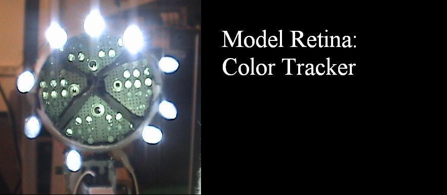
The gift of sight is precious; that is why we tried to model an artificial retina with the properties of color detection, saccades, and pursuit tracking.
Structure of a Retina:
A retina lies in the back of the eye and consists of a layer of photoreceptor cells called rods and cones. The cones are responsible for color detection in light, and there exists three kinds of cones that respond to long, medium, and short wavelengths; these typically have peak wavelengths of 564, 534, and 430 nanometers respectively. When the correct stimulus is applied, this sends distinct action potentials through the retinal ganglion cells, which get interpreted by the brain as perceived color.
RGB Light Representation:
In terms of colored light, almost any color can be formed by adding different amounts of red, green, and blue light. This is a technique familiar to almost everybody and is utilized ubiquitously in televisions, graphic editing software, etc. We will be modeling our retina by utilizing simple red, green, and blue photodiodes. We will utilize this ability to detect color to implement a scheme to track specific colors through saccades and pursuit movements with the use of servomotors and photovoltaic light sensors.
Rationale and Sources for the project:
When choosing a project topic, we were both interested in something that had to do with neural modeling. We asked Professor Land if he had any recommendations, and he directed us to the project page on his website (which can be accessed simply by Googling his name.) We thought the Lateral Inhibition project was interesting, so we decided to try to model an artificial retina. We also created a control interface to the eye using an LCD touch screen. The driver for this graphical LCD was obtained from the Spring 2006 Final Project, HDD clock. We also learned how to use servomotors by looking at the Swing Bot project in spring 2006. Other than these, we did not use any other sources when designing our project. However, we did find some sources that we tried basing additional features on, which ended up not working.
This project exists for the purpose of biological and neural modeling; it is not intended to be a toy (though it may amuse some people). There are an abundant amount of reasons for neural modeling. The primary reason is to create something that exhibits the behavior of particular neural systems. In our case, we model how the visual system processes image movement. There are two basic structures for eyes in nature; one that exists by using a waveguide structure to detect light, and one that uses lenses. Typically, insects use the former, and humans use the latter. Since we found it to be an easier structure to build, we create a quadra-sector retina, each with their own set of photodetectors. In this way, we can decouple these sectors from direct light and achieve crude position sensing. With this physical structure, having the opposite ended detectors can allow for differential input values which makes edge detection of objects possible.
There are no relevant patents or standards that involve color tracking artificial retinas related to our purposes.
Background Math:
There is no complicated math required besides for scaling and comparing ADC values and the intuition of geometry for how light reflects off surfaces. We also attempt to use some form of a proportional difference control system. The eye processes movement by constantly analyzing derivatives of edges in time and space. In our program, we analyze derivative values in time for each position sensor with itself, as well as the difference between values of the left & right position sensors and the top & bottom position sensors. In this sense, we decouple the yaw and pitch movements of the eye and move them independently.
By comparing the magnitudes of the ADC readouts of the pair of position photodetectors to be compared, we can acheive the direction in which the retina needs to turn in order to center itself on a presented object. However, this difference tends to make the movement overshoot. This is rectified by adding the derivative terms to minimize the overshoot errors. More on how this was implemented will be described in the software section.
Logical Structure:
Since our prototype eye had to be under 50 dollars, we could not follow any current artificial eye projects that we found on the web. We decided to use cheap LED’s to model the red, green, and blue cone receptors in the retina. Realizing that we cannot detect color accurately with cheap LED’s since they are not the most sensitive things in the world, we decided to quantize the representable color values for each color. We had initially tried to have 4 levels of color intensity for each RGB value to represent 4^3 = 64 different colors. However, since the resolution of our LED voltages were so low, we decided that it was realistic to achieve 9 different colors: White, Red, Green, Blue, Dark Red, Dark Green, Teal, Yellow, and Pink.
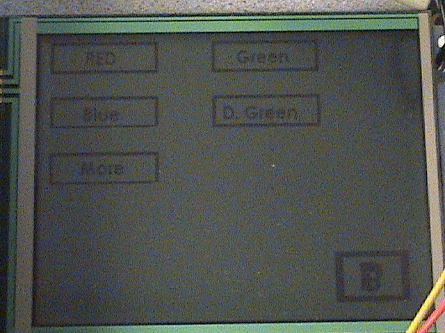
The logical flow of our program is as follows. Upon reset, there is a title menu that gives two options: Search or Tracking Mode. Search Mode allows the user to move the retina freely by pressing or dragging his finger on the LCD touch screen. The coordinate on the touch screen map onto the ranges of where the retina can move. When a detectable color is in site of the retina, the name of that color will be displayed on the screen. For Tracking Mode, the user will be presented with nine different colors to choose. Until the user chooses a color and until that specific color is recognized by the retina, it will move in a square pattern in an attempt to look for that color. Once the color is recognized, it will begin tracking that color and not move unless it sees that specific color.
Retina Construction:
The hardware construction was by far the most time consuming and irritating process of this project. The construction of the eye itself was extremely time consuming. Since we were building a color sensor that needed to be directed towards an object, we had to find a way to block out interference noise (anything emitting unwanted light, such as room light).
We wanted to show that we could model a retina (and build a decent color sensor) using bare bone LEDs that were in the lab cabinets. We spent several days performing rigorous proof of concept tests to determine whether this scheme would work.
The results of these tests showed that red, green, and blue LEDs could indeed create a crude color sensor. A red led will produce a current if light with a wavelength less than or equal to red wavelengths (~ 630 nm ) is shined on it. The same goes for blue and green LEDs (~470 nm and ~525nm). However, if the LEDs have a colored cap on it, this has the effect of band-passing the light that can enter the LED. Remarkably, we found that red LEDs are bandpassed very well and only respond to red light. Green LEDs respond to green wavelengths and everything below (including blue light). Blue LEDs came with clear caps, so they would not be bandpassed, but since blue is at the end of the visible light spectrum, the band-gap below blue is so large that blue LEDs detect only blue.
By providing a very bright source on a single LED of any color, the LED can produce up to a volt between its leads by generating a very small current. In this sense, they act somewhat like photoactive current sources. At room light, we can expect that a single LED operating in photovoltaic mode would produce very small current (in the order of microamperes), we needed to connect many of the same colored LED’s in parallel to produce enough current that would be detectable by the MCU ADC. We take 16 red LEDs in parallel, 16 green LEDs in parallel, and 24 blue LEDs in parallel. We found that the blue LEDs are much weaker in detecting blue light than red and green LEDs, therefore we clustered more blue LEDs in parallel to increase their relative current output. We needed to connect these parallel LEDs on an appropriate surface to create our color sensor.
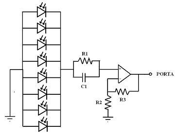
The current output would have to be connected through a large resistor (7.5 MegaOhms) so that the current will result in a voltage drop across the resistor which will be used as an input to the ADC. A capacitor was put in parallel to such a resistor in order to make the voltage across the resistor more stable. This capacitance value had to be very small in order for it to charge and discharge very rapidly in accordance to the change in the Led current output; we set it to equal 2.2 nanofarads, which yielded fairly stable results on the order of hundreds of millivolts. The voltages across the resistors and capacitors which correspond to each color were amplified by using a non inverting amplifier which was powered by a 5 Volt power supply. This output of the amplifier is fed into the ADC of the MCU. The governing equation goes as follows:
Vout = Vin * (1 + R3/R2)
It turns out that the retina is most sensitive to green since its wavelength stimulates two cones instead of only one. Not surprisingly, green leds were the most sensitive, which is also due in part to the fact that the green leds picked up blue wavelengths constructively. For this reason, the green leds were amplified by a factor of 11 whereas the other colors were amplified by 16. The photodiodes were amplified by a factor of 11 as well since they were qute sensitive.
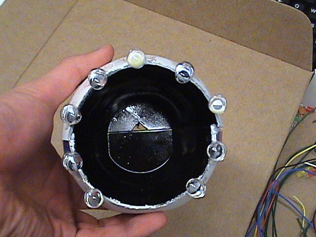
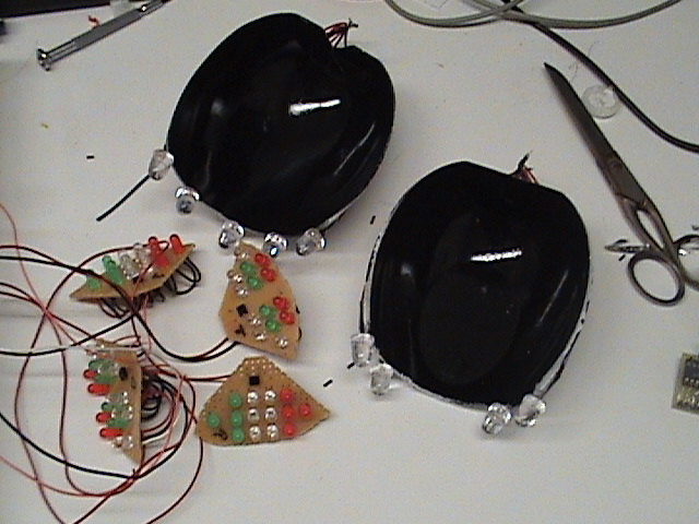
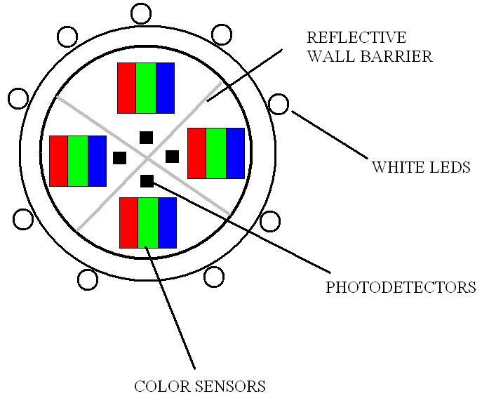
We found an Easter egg shaped container in the trash…and decided to use that as our retina shell. We painted it white on the outside to reflect outer light and black on the inside to absorb any negative light effects on the inside. The color sensor was built on a solder-board that was cut into a circular shape to fit into the shell of the eye. This solder board was segmented into 4 sections to represent: up, down, left, and right. These sections were partitioned with aluminum foil to help isolate light in each section. Clusters of Red, Green, and Blue Leds were fit onto the board in an evenly distributed pattern. These would be used for RGB detection and calculation. Four photo-detectors were placed on the top, bottom, left, and right sides of the solder board segments, with the intention of using these for position detection. These segments were hot glued into place inside the retina shell and a four sided reflective divider (aluminum foil) was used to separate them.
We used servo motors to implement precise movements and positioning. Because we wanted movement of 2 degrees of freedom (yaw and pitch rotation), we used 2 standard futaba servo motors. To better simulate the human retina, we initially tried using rubber chords together with servos that would be similar to tendons in the eyeball. However, we encountered many problems in the mechanical aspect in that the rubber chords would not position or move the eye in the way that we wanted it. After several futile attempts, we decided to use a much simpler mechanical scheme: one servo would be directly attached to another servo, and the eye would be attached to one servo to have 2 degrees of freedom. This scheme gave us precise movements and the torque of the servo was enough to overcome the weight of the other servo plus the weight of the eye. The retina shell was hot glued onto these servomotors and the servomotors were hot glued onto a wooden frame to provide height and stability.
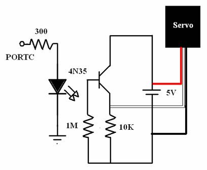
To prevent the spiking outputs of servo motors from damaging or resetting the MCU, we had to build opto-isolator circuits, which would electrically isolate the mcu from the motors. A separate power supply was used for this.
When we detect color using the LEDs, we found out that the LEDs give off more current when there is a concentrated source of light directed from behind the retina. This will make the intensity of the reflected light off the object greater, thus making the sensors more sensitive to presented objects. Therefore, we decided to mount large, bright LEDs that could take up to 12 Volts, which would help us get better outputs from the LED’s and the photodiodes. These LEDs were extremely directed, so they did not affect the measured readings unless an object was directly in front of the retina shell.
The State Machine:
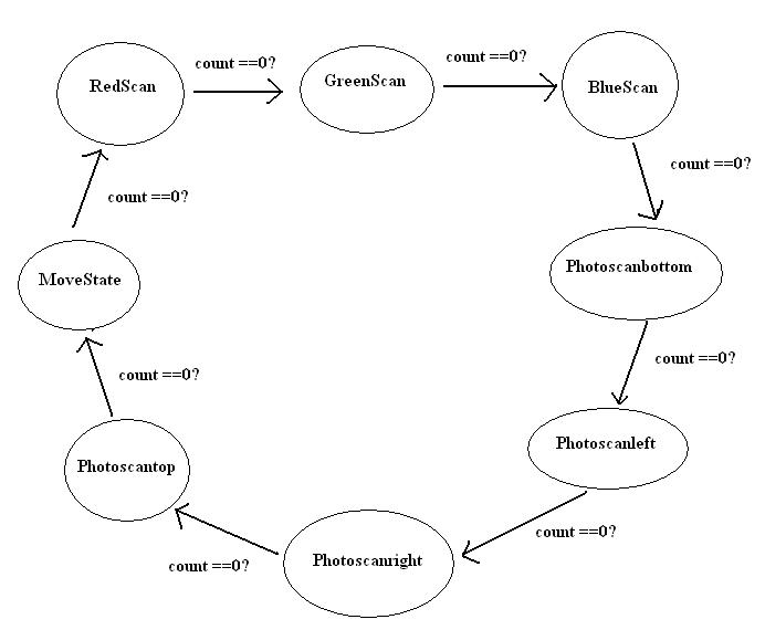
Since we wanted our eye to make motion related decisions after every new ADC values, and the state machine did not have to cycle fast for our timing scheme, it made sense for us to group the tasks of sampling, tracking and searching together to make one big state machine. This state machine is controlled by the variable named MainState, which takes the state definitions: RedScan, GreenScan, BlueScan, Photoscanbottom, Photoscanleft, Photoscanright, Photoscantop, and MoveState.
The ADC condition was initialized by setting the following:
ADMUX = 0b01100000;
ADCSR = 0b11000111;
Here, we want to point out that the ADMUX.7 and ADMUX.6 were set to 0 and 1 respectively, instead of the values 0 and 0 used in previous labs. Because the PCB board connects the AVCC with the AREF input of the Atmega32 through an external capacitor, this ADMUX setting allows to use the AVCC (5V) for voltage reference in analog to digital conversion.
To implement our sensors (LED’s and photodiodes), we needed 7 different ADC inputs to poll values for: red, green, blue LED, and left, right, top, bottom photodiodes. Since the MCU can only read from one ADC input at a time, we had to design a state machine that would quickly analyze the changing ADC inputs that was read by the MCU in real time. The 7 ADC values are converted in every appropriately labeled state except MoveState. The motor movement is handled inside MoveState depending on whether the flags ControlMove or TrackMove are set. If ControlMove is set to 1, then the control mode will be entered and the user can move the eye with his finger on the touch screen. If TrackMove is set to 1, then the tracking mode will be entered where a color will be searched for.
Color Detection:
As mentioned in the Introduction, almost any color of light can be represented by using RGB values. To detect color, we quantized the outputs of LED's to different levels while sampling them (Red_High, Red_Mid, Red_Low, Green_High, Green_Mid, Green_Low, Blue_High, Blue_Low). The amount of current generated is proportional to the intensity of such light, but not linearly. Because of this, it was difficult to scale, and was mostly done by trial and error. Choosing the thresholds of different levels needed extensive and repetitive testing of holding different colors in front of the eye and reading the corresponding LED outputs from the ADC. For instance, to choose threshold values for the color red, we grouped the different colors in 3 groups: colors that have high red level (white, red, yellow, pink), colors that have medium red level(dark red, green), and colors that have very low red level (dark green, blue, teal). Then we chose the right threshold values for red that would distinguish one of these groups from another. In the RedScan state, we ended up quantizing as following:
//Quantize the red detection to 3 regions
if(AinR >= 9)
red = Red_High;
else if (AinR >= 5)
red = Red_Mid;
else
red = Red_Low;Then, in the MoveState, we calculated the value of variable color, according to what level of red, green, and blue that color corresponded to. For instance, the color yellow was to be detected when red == Red_High, green == Green_High, and blue == Blue_Low. The value of color was then converted to GUI text display and displayed on the LCD.
Servomotor Control:
Controlling the servo motor needed great precision, because the servo requires an input pulse that has period of 20ms. The valid range of pulse widths are roughly from 0.55ms to 2.2ms (0.55ms corresponds to movement of 0˚ and 2.2ms corresponds to 180˚). To accurately implement the pulse, we used the timer0 compare match interrupt and set the register values as the following:
TIMSK=2; //turn on timer 0 cmp match ISR
OCR0 = 34; //set the compare reg to 34 time ticks
TCCR0=0b00001011; // clock/64 and enable interrupt
In this scheme, each interrupt occurs at a period of : (1/16M) * 64 * 34 ≈ 0.136ms . Then, in the interrupt, we declared the following:
if(pwidth == 148)
{
PORTC.6 = 1;
pwidth = 0;
}
else if (pwidth == widthLR)
PORTC.6 = 0;
pwidth++;
Since 0.136ms * 148 ≈ 20ms, counting the variable pulsecount up to 148 gave us a fairly accurate period of 20ms, which is necessary for the servo. At the start of every 20ms, the pulse is on and when pulsecount reaches the value of the variable widthLR, the pulse goes off. This method gave us the ease of being able to adjust the motor position by changing widthLR in main(). We found out through testing that the servo takes in valid widthLR values from 4 to 16 (0˚ at widthLR = 4 and 180˚ at widthLR = 16). We also had a variable widthUD that would give pulse to the servo that controls up down movements that is controlled in exactly the same way. We found that a good range for the eye to move was widthLR = 6 to14 and widthUD = 9-11; the pitch movement of the retina was limited to simulate natural movement as well as reduce harmful noise effects from ceiling lights.
Tracking
We used comparison of the two pairs of photodiodes for tracking (left/right and top/bottom). Initially, we tried to directly compare the output of Photoscanleft and Photoscanright and have the eye move to the left if Photoscanleft was larger than Photoscanright (which means left side is brighter than right), and move to the right if the other condition occurred. However, even after careful calibration, this method proved to be extremely difficult primarily because of room light and overshoot. As the eye was moving, there would be some moments where the side of the eye that does not have the object in front it, actually is detected to be brighter because of external light. After extensive testing, we found out that using the derivative values of the photodetectors, together with their direct current output values gave the best result for tracking because it marginalized the effect of noise light error and introduced edge detection.
In each of the states, Photoscanbottom, Photoscanleft, Photoscanright, and Photoscantop, we calculate the derivative (or delta) of the output of each photodiode by keeping track of the past value and subtracting that value from the current ADC value. This is done as follows:
Ainbottom_old = AinPhotobottom;
AinPhotobottom = ADCH;
BottomDeriv = AinPhotobottom - Ainbottom_old;
Tracking movement is implemented in the function EyeTrack() which is a state machine that gets executed during the MoveState of the main state machine. The overall movement design is done so that initially the eye rotates in a square path looking for a user specified color. Once the eye detects that specific color, it locks position so that it is directly facing the color. If the specified color material moves, then the eye tracks/follows the material.If the eye detects the user specified color while initially rotating, it moves from the rotating states (Right, Up, Left, Down) to SearchDone state. In this state, there is no motor movement (because it is already focused at the correct color). However, if in this state, the eye no longer detects the same color (because the material is moved) then it goes to TrackObject state which is the state in which the eye follows the colored object. In this state, it also constantly checks if it is tracking the correct color. As explained earlier, comparison of derivatives of photodetector outputs were used in concurrence with their absolute values for optimal tracking. If the one side of the eye has greater derivative and greater absolute value, then it means that the object is moving in that direction but getting out of the range of the eye. Therefore, the eye has to rotate towards that side. The following shows how up/down tracking was implemented:
//Up/Down Tracking Movement
//If top side is brighter than bottom, and top's derivative of intensity is greater than bottom's, rotate up
if ((abs(TopDeriv) > abs(BottomDeriv)) && (AinPhotoTop > AinPhotobottom))
{
if (widthUD >9)
widthUD --;
}
//If bottom side is brighter than top, and bottom's derivative of intensity is greater than top's, rotate down
else if ((abs(TopDeriv) < abs(BottomDeriv)) && (AinPhotoTop < AinPhotobottom ))
{
if (widthUD < 11)
widthUD ++;
}When in the track mode, the function EyeTrack() is called. This enables a second state machine that controls the pulse width for the yaw and pitch motors. The following state machine shows how the tracking mechanism was carried out:
Searching
In the Searching mode, we made it so that the user can rotate the eye to the position corresponding to the touched spot on the LCD. Also, we made it output the color the eye is currently detecting at the bottom of LCD. The controlling portion was done by polling the coordinates of the touch on the LCD and making corresponding pulse widths on the servos. Since the dimensions of the LCD are 320x240, we had to scale the regions to be touched accordingly:
To detect color, we quantized the outputs of LED's to different levels while sampling them (Red_High, Red_Mid, Red_Low, Green_High, Green_Mid, Green_Low, Blue_High, Blue_Low). Then, in the MoveState, we calculated the value of variable color, according to what level of red, green, and blue that color corresponded to. This value was converted to GUI display and displayed on the LCD.
Jitter Feature
One of us thought it would be interesting to model an action where if there is a sudden large exposure to light on the retina, it would tremor for about a second by jittering up/down and left/right. This was set by the condition of an event with a large differential exposure to light on one of the photodiodes. The action was carried out by rapid changing positions with both servomotors.
LCD TOUCHSCREEN:
As mentioned before, we are using the same LCD Touchscreen as the ECE 476 group that did the Hard Drive Clock in Spring 2006. We utilize the drivers that they provide and make slight modifications to its library functions.
This particular module, Microtips USA MTG-F32240N, was purchased as self contained, meaning that it has all necessary chips on board and is a 320x240 pixel Graphical Display. The screen is controlled using a 26 pin cable. 12 pins are for controlling the LCD display, and another four are for the touch screen data lines. The rest are for power, settings and auxiliary inputs. The logic level pins were attached to a microcontroller in order to drive the display and read the touch screen output. The connections are made from the LCD module to the MCU by using a flat flex zif connector adaptor. This module is large in size and therefore requires a large amount of power to run. Its typical voltage rating of operation is at -16.7 volts and needs reference voltages of approximately -24.5 and 4.5 Volts. It is a standalone unit and no internal modifications were needed to be made. It contains a backlight that can be powered with 3.6 volts.
Pins 1, 2, 3, and 17 are all power related. Pin 4 tells the screen if the bits on pins 7 through 14 represent a command or data while pin 5 tells the screen if it is being read from or written to. Pin 15 is toggled on and off at various points while sending data to the screen to ensure that the controller chip is only active while the MCU is talking to it. RST remains high during normal operation of the screen. SEL1 should also remain high at all times, and therefore we connected it to a fixed 5V.
In order to display graphics and alter pixels on the LCD display, first a command must be sent to the screen signaling where the following data is to be displayed. Next, 8 bits (one byte) of data are sent to the LCD controller. These bits represent the 8 pixels to the left of the current cursor position. In order to display the complex GUI, a MATLAB program was used to convert a black and white bitmap image into a C header file. Every 8 pixels from the bitmap are stored as a single byte variable in the header file. A byte is written to the screen, the cursor is then advanced to the left by 8 pixels, and then another byte is written. This process is carried out for each button, and then for the rest of the graphics. The display is also capable of sending the current state of each pixel back to the MCU. This command is useful for checking that the display has received the data correctly, or for doing different effects, such as inverting a region of pixels. Auxiliary commands also exist to initialize the display and to set certain options about the display.
This particular screen is a resistive 4-wire panel that is connected to a Texas Instruments ADS7843 controller. Although 7 pins are made available to the controller, only 4 are needed. The others pins (Auxiliary Input 1, 2, and Pen1, and Pen2) are not required. This controller is connected to the STK500 via Serial Peripheral Interface on PORTB. PORTB is the only port that can handle this alternate function. Essentially, the two location coordinates of the screen, x and y, are determined by a calculated resistance differential due to the nature of how the screen operates. The Touch Screen Controller converts this analog pulse into digital information through ADC channels. This information is scaled and mapped to match the pixel size information of the LCD screen. Since the 476 team used 8-bit samples per axis, we are using the same convention. We are also using the team’s GUI widget implementation, which adds a button with defined boundaries onto the display. The touch screen scaling must be calibrated to match those boundaries.
The use of the SPI of the ATMega32 is required by the 4-wire touch screen. SPI is an inter-integrated circuit communication interface that works very fast and with great simplicity. There are 4 pins dedicated to SPI on PORTB:
PB7: SCK (SPI Bus Serial Clock)
PB6: MISO (SPI Bus Mater Input/Slave Output)
PB5: MOSI (SPI Bus Master output/Slave Input)
PB4: SS (SPI Slave Select input)
As shown above, the structure of SPI consists of a slave IC and a master IC. Information is exchanged between slave and master through 8-bit shift registers by the master’s clock. The slave and master IC’s are connected by PB5-PB7. The slave select’s purpose is to balance the transfer of packets of information between the two device. In our case, the Touch Screen is the master IC and the LCD is the slave. As can be seen on the Microtips Datasheet, the four pins above match the purposes of the four wire’s dedicated to the touch screen panel.
To operate with SPI, PORT B had to be in the correct settings as shown in touch.c. The SPI allows the coordinate data to transfer when the screen is being touched and data registers are shifted accordingly. If the screen is not being touched, the coordinates are set at x=500 and y=500, which are greater than the 320x240 dimensions of the screen.
The drivers we used had a GUI constructor library provided in gui.c. The function GUI_add_button() allowed us to add bitmap images that could function as widgets. This means that if the polled coordinate of the touch screen falls within the boundaries of the widget image, whatever function that is tied to that specific widget will be called. The specific coordinates are checked to see if they are in the boundaries of the widget image with the function GUI_poll(). GUI_poll() is called inside the beginning of MoveState since it is in this state that the motor control is taken care of. A function called GUI_remove_button() was added to the library we had so that we could remove buttons that were already added to the GUI frame. This is done by decreases the GUI number counter and reducing the widget area to 0. These functions were used to book keep how many gui buttons needed to be added or removed when we scrolled through different menus. No errors occurred in the final version of the program, so it is safe to assume that the GUI_remove_button() function worked.
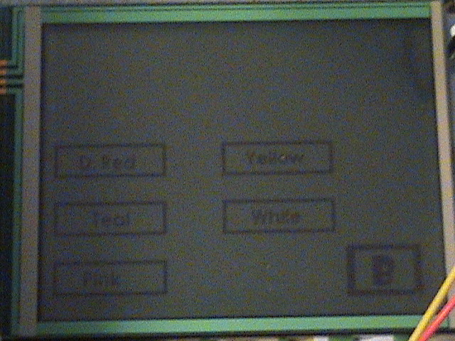
The header file bitmap.h was created with matlab to create the bitmap images that can be seen on the screenshots below. This was achieved by importing a bitmap file into matlab, where the pixels are processed as zeros or ones. These are used in conjunction with the LCD driver functions to display them on the screen. For more information on how to use this particular touch screen LCD, refer to the ECE476 spring2006 project: HDD clock with LCD touch screen.
In retrospect, this was not the best project choice for us. Trying to use light is hard enough due to all the interferences ranging from room light and lights from devices. But trying to gather data using cheap sensors amidst all these interferences was extremely tedious and frustrating to calibrate. We would constantly be revising our proof of concept of whether our scheme would work well or not, and we would always get consistently varying results. However, we did the best we could in trying to stabilize results with the given time frame and got a taste of some control theory. It would have been wise to have taken some courses in control feedback systems before attempting a project like this.
Color Detection:
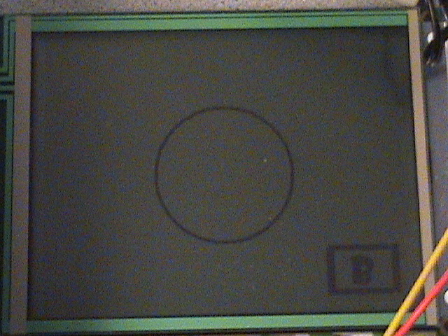
The primary function of the Eye-Robot was successful in that it was able to detect and differentiate 9 different colors (at a distance within 4-5 inches). In the “search” mode, the eye will move according to the user control using the LCD touchscreen and the LCD will display what color the eye is detecting.
R
G
B
Color
L
M
L
Dark Green
L
M
H
Blue
L
H
H
Teal
M
L
L
Dark Red
M
H
L
Green
H
L
L
Red
H
M
H
Pink
H
H
L
Yellow
H
H
H
White
(H: high, M: mid, L: low/none)
Although we were able to meet the specs above, we could not meet our initial goal of differentiating 64 different colors. In the beginning, we hoped to quantize each color to 4 different levels, so that we could get a 6-bit resolution (64 colors). However, even after extensively trying methods of amplification and noise reduction (trying to block outside light), the output voltage of LED’s were not large and consistent enough to be quantized to such numerous levels. For red and green LED’s we used large amplification and managed to divide the region to 3 scales for each color. But the blue LED’s gave us very poor output voltages which were just enough for us to examine whether the blue LED gave high voltage or low.
Tracking :
In “tracking” mode, the eye would track a user specified color. The result was satisfactory because the eye would lock onto a specific color that the user wants, and move in the direction of color if the color moves. However, if more time were allowed, we could have made some improvements in tracking. The motor movements were not smooth as we would have liked and sometimes it showed some hesitant movements. We are nontheless glad that it worked as well as it did.
Speed of Execution :
We encountered no problems in the speed of execution in implementing Eye-Robot other than for one gui menu. On the tracking menu, we initially had all nine buttons being polled for the nine different color options. This slowed down the system tremendously. To solve this, we split up the number of buttons into two different menus, and this solved the timing issues. Other than this, our interactive system was well-built in that as soon as we gave a command in the LCD touchscreen, the eye would perform the corresponding operation. In control mode, as the user drags his hand across the touchscreen, the eye almost instantaneously move according the location corresponding to the finger touch.
Accuracy :
The color that was detected by the eye was accurate when we tested with the 9 different colors stated above, within roughly 4 inches from the retina. If the color moves beyond the detectable range, the system will not output a correct color, since the LED voltage outputs will drop and the eye confuse the color with another color that is lower in the RGB value.
In tracking mode, Eye-Robot displayed some hesitation movements which were primarily due to room light. Because we were mainly just using 2 pairs of photodiodes to track objects, it was nearly impossible to track not being affected by external noise. When we tested in darker room conditions, the tracking gave much better results. Since the tracking is based on derivatives in space according to time, the retina is signaled to move based on whether or not it sees the edge of an object of one color type relative to an edge with another color type. This edge detection was pretty stable in that it followed objects according to rate of movement change with respect to its background.
The pulses given to the servo were very accurate in that we managed to position the servos in the exact place we wanted at the right time.
Usability by Us and Other People:
Our interface is very user friendly because every function and its output are displayed on a wide LCD touchscreen. The only thing that the user has to have in mind is that he has to be extremely cautious in handling the retina because it consists of multitude of wires and therefore can be very fragile, especially the custom adaptor for the LCD screen.
What didn’t work:
When coming up with the idea to build an artificial eye, we looked online for relevant projects that have been done. We found a project called the MAC-EYE which was conducted at the University of Genova. This project modeled two tendon driven eyes, which were rotated by using DC-motors and pulleys. The image collection was done with CCD cameras. We found that the CCD portion of that project was irrelevant to ours, but rotating the eyes with a pulley scheme was interesting. The paper talks about how they governed the movement with Listing’s Law, which is a set of equations that model eye saccade movement. However, after about 3 weeks of trying to mimic this, we found that this could not be done with our limited resources and time. Therefore we settled on using the two servomotors as described before.
In addition to color tracking, we wanted to add another retina modeling scheme that exhibits lateral inhibition. We would use the four photosensors as four neurons and output simulated action potentials on a digital oscilloscope on the LCD screen. However, we didn't have nearly enough time to accomplish this. We acheived about half of what was needed to be done, but it was not demo-able.
---------------------------------------------------------------------------------------------------------------------------------------------------------
IEEE Code of Ethics:
We, the members of the IEEE, in recognition of the importance of our technologies in affecting the quality of life throughout the world, and in accepting a personal obligation to our profession, its members and the communities we serve, do hereby commit ourselves to the highest ethical and professional conduct and agree:
1. to accept responsibility in making decisions consistent with the safety, health and welfare of the public, and to disclose promptly factors that might endanger the public or the environment;
2. to avoid real or perceived conflicts of interest whenever possible, and to disclose them to affected parties when they do exist;
3. to be honest and realistic in stating claims or estimates based on available data;
4. to reject bribery in all its forms;
5. to improve the understanding of technology, its appropriate application, and potential consequences;
6. to maintain and improve our technical competence and to undertake technological tasks for others only if qualified by training or experience, or after full disclosure of pertinent limitations;
7. to seek, accept, and offer honest criticism of technical work, to acknowledge and correct errors, and to credit properly the contributions of others;
8. to treat fairly all persons regardless of such factors as race, religion, gender, disability, age, or national origin;
9. to avoid injuring others, their property, reputation, or employment by false or malicious action;
10. to assist colleagues and co-workers in their professional development and to support them in following this code of ethics.---------------------------------------------------------------------------------------------------------------------------------------------------------
We have stood by the IEEE code of ethics during the course of our project. As Electrical Engineering students, we realize that this code exists so that those of us who do go into industry or practice may have a consequential impact on society. In particular, despite the intention of trying to do good, a flawed design with good intentions can put the public in grave jeopardy. For instance, the case of the Therac25 discussed in class is an extreme example of how responsibility must be taken and all manners of safety factors should be disclosed to the public. We have followed these safety standards by trying to stay with low voltage circuits, with the exception of the LCD and high powered LEDs. If anyone or anything were to be damaged, we fully accept responsibility for our decisions and disclose any information to our peers and on this website about any dangers that may be involved with this project.
We have found no real conflicts of interest with this project. Despite this, we tried to remain motivated and honest throughout the project design period. Falsifying information or claims would be counter productive in the final product and restrict us from receiving useful help from our peers and our instructors. The code which states to reject bribery is not a problem in that we have no received, nor would we accept any bribes in any form.
We attempted to improve our understanding of technology and competence by working with basic level photodiodes to create a color sensitive model of a retina. This abides by the IEEE code of ethics in that this has given us a greater understanding of potential applications of devices of this nature. We have garnered experience by building upon our current technical skill levels and have not tried to go far beyond our limitations.
Within the design process, we constantly seeked and reciprocated feedback and support among our fellow peers, the TAs, and Professor Land. We have utilized programs and techniques from old ECE476 groups and have accredited them appropriately. Regardless of age, sex, gender, religion, and national origin, we believe we have treated all members that we have encountered fairly without discrimination. We think that it is great to work in a diverse class and laboratory. We also treat all of our fellow peers with utmost respect, encourage them with moral support and values, and respect their work and property.
Acknowledgements
We would like to thank the entire Bruce Land, our TA Kashif Javed, and the entire ECE 476 staff for providing a great class this semester. We could not have gotten anywhere without the advice and encouragement that was given.
We would also like to thank the vendors Parallax, Vishay, and Avnet for the parts that they were able to generously sample us.
APPENDIX A: PARTS COST LIST
Atmega 32 1 $0 Sampled from AVNET Custom Protoboard 1 $ 6 4N35 Optoisolator 2 $0 Free from lab Servo Motor 1 $0 Sampled from Parallax Servo Motor 1 $10.50 5mm Blue LEDs 24 $ 1.00 ebay 5mm Green LEDs 16 Free (in Lab) 5mm Red LEDs 16 Free (in Lab) 10 mm White LEDs 9 $ 4.05 Purchased from Ebay Photodiodes 4 Sampled from Vishay Wooden Stand 1 Free (junk) LCD Touch Screen 1 Previously Owned (purchased Summer 2006) Power Supply for motor 1 $ 5.00 Power Supply for opamps and white LEDs 1 $ 5.00 BreadBoard 1 $ 6.00 Solder Board (large) 1 $ 2.50 Eye Ball Shell (Easter Egg) 1 Free (junk) Op Amps LM358 7 Free (in Lab) TOTAL COST $ 40.05 APPENDIX B: SCHEMATICS
All relevant schematics are shown in the above sections.
APPENDIX C: WORK DISTRIBUTION
| Team Member | Tasks |
| Stephen J. Jhun | Soldered the Color Sensor |
| Soldered the Protoboard | |
| Sampled/ordered Parts | |
| Worked on Color Detection | |
| Worked on Position Detection | |
| Eye Hardware Construction | |
| Worked on Lab Report | |
| Worked on LCD control |
| Seung-Jae Bang | Tasks |
| Worked on the Jitter Feature | |
| Worked on Position Detection | |
| Worked on Color Detection | |
| Worked on Lab Report | |
| Worked on Motor Control |
APPENDIX D: REFERENCES
References
Code
** with the exception of FinalCode4.c and bitmaps.h, the other files are source files used from Spring 2006, ECE 476 HDD clock. The file gui.h has been modified with a GUI_remove_button function.