![]()
![]()
![]()
![]()
![]()
![]()
![]()
![]()
![]()
Sound Source Triangulation Game
By: Bohnish Banerji and Sidharth Pande
The goal of this project is to determine the time and location of a sound source in all three dimensions (x,y,z) using an economical and easily reproducible setup.
To accomplish this goal, we decided to try and triangulate the sound source using a 4 microphone configuration. We used the Atmel Mega32 microcontroller to detect the sound pulses from the microphones. The triangulation calculations are then executed on the data gathered resulting in the 3 dimensional position and the time of the sound source. The next part of the project was to apply this position determining algorithm to play a simple game on the TV: the game prompts the player to clap at a certain position. After the player correctly claps at the location, the game then proceeds to prompt the player to clap at new locations. The game keeps track of the number of mistakes made by the player.
![]()
The sound triangulation scheme was influenced by the Global Positioning System (GPS), which triangulates the location of a receiver using satellites and the speed of light.
The fundamentals of the triangulation idea are derived from the assumption that speed of sound is constant. Thus we were able to determine the distance between a microphone and the sound source using the speed of sound and the time it takes the sound wave to propagate to the microphone. The figure below depicts this idea.
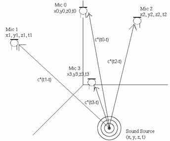
Figure 1 - Sound Triangulation
The equation below describes the relationship between the speed of sound, c, the location of the sound source (x,y,z), the location of the nth microphone (xn,yn,zn), the time of the sound source transmission (t), and the time of the sound source reception (tn) .
![]()
![]()
Equation 3 - Newton
Raphson Matrix Equations
The update vector, ∆x, can be solved for with the
equation below:
![]()
Equation 4 - Guess Update Equation
These equations allow us to update our initial guess to get closer to the actual solution. We have found that it takes about 5 iterations to arrive sufficiently close (within 1 µm) to the actual solution. We used Matlab to verify these equations and prove their correctness by reverse engineering problems. Details of this testing will be discussed later.
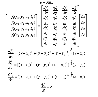
A high level schematic of our data flow is given in the figure below:
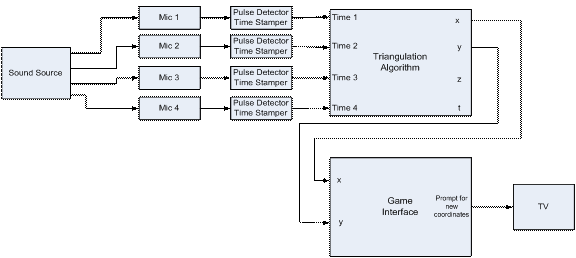
Figure 2 - High Level Schematic
The schematic provided above is mostly self-explanatory. A sound source (hand clap) triggers the microphones. The pulses are received by the Mega32 which then time stamps each of them. We only need to have the time stamps be accurate relative to the other microphones. Using these time stamps, we are able to apply the triangulation algorithm to converge to a solution. This solution is given to the game interface which processes it and prompts for a new location.
A hardware and software tradeoff emerged with regards to the pulse detection and timing. Initially, we wanted to send the outputs of the microphones to the ADC unit in the Mega32. We would process this signal in code to determine whether a sound source had been detected. This idea would require minimal hardware and considerable software signal processing. We would need to deal with multi-pathing errors which would be difficult to identify in a voltage signal. The other option was to use amplifiers and Schmitt triggers to send a CMOS logical signal to the port pins of the MCU. This scheme would require additional hardware but would make the signal much easier to decode in software. In the end, we decided to go with the second option and use the port pins. The biggest advantage of this scheme is it would be easier adhering to the strict timing requirements of the composite signal to the TV. It would be considerably difficult to poll the ADC on 4 channels as well as process the signal while being able to generate the sync pulses required for the TV. This would create many errors in the time stamping which would have a big effect on the triangulation of the solution.
![]()
Initially we tried to use 4 omni-directional microphones for our project. These produced little to no change in output. After days of testing and debugging these microphones, we decided to try uni-directional microphones. These gave a much better result using the exact same setup. A schematic for the microphone pulse detection circuit is given below:
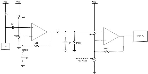
Figure 3 - Microphone Circuit
The microphones were hooked up as specified by the data sheet given in the references. The 1µF capacitor on the output terminal of the microphone acts to nullify any unwanted DC offsets. This signal is then given a DC offset of 2.5V before being sent to the first op-amp which is configured to be a non-inverting amplifier with a gain of 100 (1MΩ / 10kΩ). This amplified microphone signal is sent through a diode to rectify the signal. The RC circuit (51kΩ/1µF) maintains the voltage amplitude at the peaks of the signal with the expected RC discharging behavior. The output of this block is sent to the Schmitt Trigger. The 1MΩ resistor causes most of the feedback voltage to drop across it which ensures that the width of the Schmitt Trigger’s hysteresis curve is small. The 10kΩ resistor and potentiometer is used to determine the trigger voltage. The potentiometer is tweaked until the signal gives a clean pulse for sound sources. Some pictures taken from the oscilloscope demonstrating the sound source triggering behavior are shown below:
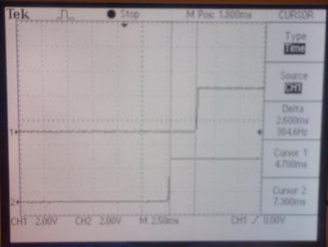
Figure 4 - Oscilloscope Picture
This circuit outputs a 5V signal when there are no sound sources detected. When the user claps his hand to within approximately 3m of the microphone, the circuit outputs a 0V signal. These levels can be easily detected by the port pins of the MCU.
From the microphone circuits, the signals are routed to the STK-500/Mega 32 port pins. We use Port A as inputs for the microphone signals. These signals are inverted and sent to Port C which drives the LEDs on the STK-500. This causes LEDs to light up when a sound source is detected. This serves as a check to make sure that the microphones are able to pick up a sound impulse. A simple schematic is shown below:
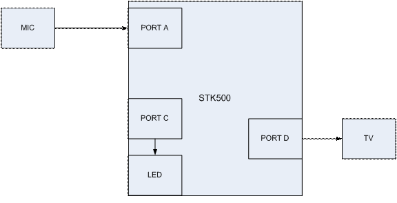
Figure 5 - STK-500 Connections
The TV composite cable is driven using the DAC circuit shown below:
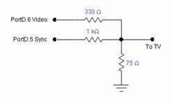
Figure 6 - TV DAC circuit
In order to ensure that the microphones stay in the same configuration with respect to each other, we needed to come up with some sort of a mechanical structure which would be unobtrusive to the player. A picture of our structure is shown below:
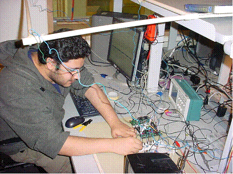
Figure 7 - Structures Pic
![]()
Matlab Triangulation Verification
In order to verify our triangulation calculations, we reverse engineered various problems in Matlab using our equations. These simulations used a predefined sound source location and a predefined microphone configuration to determine the times at which the microphones would receive the signal. Using these times as the appropriate inputs for our triangulation calculations, we were able to successfully arrive at the predefined sound source location. However, we discovered a limit for the convergence of the solution: if the sound sources were well contained within the predefined microphones configuration, only then would we be able to converge to the correct location. Otherwise the solution converges to a different location and time that satisfies our equations. Even in a GPS system, the receivers are well contained within the satellite’s configuration. There were multiple solutions to our system of equations. Therefore we decided to create a large enough structure in which a player could comfortably play.
We ran a test simulation with predefined parameters. The sound source was set to be at (1,1,1) at a time of 0. The positions were defined so that the sound source was well contained similar to the configuration in our problem. After 4 iterations, our code outputted the following:
The coordinates of the sound source are as follows:
x - 1.000007 inches
y - 1.000018 inches
z - 1.000028 inches
The time of transmission was 0.000063 seconds
It took 4 iterations.
This test case was one of few used to verify the validity of the mathematics of the triangulation calculations. The Matlab test code is provided at the end of the report.
Port Polling Scheme
To ensure that the TV would be compatible with our code, we polled Port A during the horizontal sync interrupt. This occurs every 63.625 µs. This sampling rate introduces an error in the time stamping of about 0.0190875 meters. This an acceptable amount of error in each signal. Each microphone signal was routed to a unique Port A pin. The state of these pins was stored in an array (alreadyTrigger). If the pin went low and the state is not already triggered then alreadyTrigger is set to 1 and the time is recorded. After the first pin is triggered, a separate timing variable is initialized. If this timer goes above 10 milliseconds then the state variables for each microphone are reset and the timer is reset. This signifies only 1 microphone getting triggered, which is not sufficient to triangulate. When all 4 microphones have been triggered, a flag is set which signifies that the system is ready to perform the triangulation calculations.
Triangulation
The functions listed below are implemented to perform the triangulation calculations shown earlier:
inverse4- This function take a 4X4 matrix and calculates its inverse. Each element of the inverse is calculated by multiplying specific elements of the original matrix together. Using a more advanced algorithm such as the Gauss-Jordan elimination technique may have been faster. However, the technique we implemented can be performed in a less varying number of cycles with no branches. This gives us predictable behavior that can be used with the TV under strict timing constraints.
multMatVect4- This function multiplies a 4X4 matrix with a 4X1 vector and returns the result.
addVect4- This function adds a 4X4 matrix with a 4X1 vector and returns the result.
function1- Evaluates an intermediate expression that is used in the function dfdvar.
dfdvar- This function calculates the derivatives from Equation 3 for specific values. A matrix of values, A from Equation 4, is calculated using this function.
negFunction- This function calculates each element of the vector b from Equation 4.
norm4- This function returns the magnitude of a vector. This is useful in determining whether the solution has converged.
TV Game
Our game prompts the player to clap at a specific location. The game then determines the actual position where the player claps and reports this position using the TV. The game then proceeds to prompt the player to clap at a different location. In order to have enough time to complete the calculations, we reduced the resolution on the TV.
![]()
Unfortunately, we were unable to triangulate on sound sources. To diagnose the issue, we acquired the time stamps for a particular sound source and used these as inputs in our Matlab test code (mentioned earlier). This analysis pointed to the problem of being unable to invert the Jacobian matrix, A, from Equation 4. This was due to the matrix being “ill-conditioned” and therefore scaled badly with respect to each other. Thus we were able to narrow down the problem to an issue with the time stamped inputs. To verify the time stamping technique, we tested the relative time stamps against oscilloscope readings of the same signal. We observed that any two measurements were within 0.2 milliseconds of each other. This variation could be explained by the lack of precision on the manual oscilloscope measurements. Therefore, we believe that the time stamping algorithm functions correctly. If we created a sound source in approximately the same location every time and observed the results on the oscilloscope, we noticed a few millisecond variations; with respect to the speed of sound (300m/s), this corresponds to 30 cm/ms. Variations of this scale with respect to our system would definitely cause our triangulation calculations to fail. This leaves the microphone circuit as the reason for the problem. Our circuit was not suitable to measure the time differences inherent to our system.
The problem could not lie in the fact that we had meter long wires connecting the microphones to the proto-boards. The propagation delay of electromagnetic signals through wires is insignificant compared to the speed of sound (3*108 vs 300). This also rules out the propagation delays of the operational amplifier, which is in the order of nanoseconds. However, the RC circuits used throughout the circuit could cause problems. The RC time constants were on the order of milliseconds (51000 * 0.000001 = 51 ms). The charging of 1 µF capacitors would cause phase delays, which would completely throw off our time stamping measurements. We tried using smaller capacitors to decrease charge times, but we were unable to make the circuit function properly. The time constant was too small to maintain the amplitude at the peaks, which could then be triggered by the Schmitt trigger. In addition, the capacitors used in the circuit had tolerances of 20%. These variations across the 4 microphones would cause relative time delays which would be detrimental to our calculations.
Our original game was to determine the location at which a player claps. Due to time constraints and unexpected errors, we had to rescope our game to be simpler; our game now prompts the player to clap in a quadrant. This is determined by identifying which microphone pulse arrives first. However, one of our microphones malfunctioned during this rescope and the game has been further rescoped to include only three regions.
![]()
The rescoped game works according to specifications. Although triangulation is not used in this game, to demonstrate that our original code was robust enough to meet the strict timing contraints of a TV, we inserted our triangulation calculations in the rescoped game. We observed that the TV displayed text fluidly without any flickering. We were able to fit the polling scheme in the horizontal interrupts without causing any problems.
The rescoped game with the three microphones configuration was able to successfully detect hand claps in the appropriate three regions. To ensure that players would not deem the structure to be obstructing their game, we placed the structure over their heads. One externality that we had to deal with was caused by the noise levels in the lab. Random noises would cause the microphone circuits to trigger. This project can be easily used by others as our interface is very user friendly.
![]()
We were extremely disappointed that we were unable to get our triangulation scheme working. Our configuration is very easy to setup and could be very useful if it worked properly. We spent too much time debugging and working with the omni-directional microphones and we could have used this lost time to debug our circuit and thus perhaps have our triangulation scheme function correctly. Also, initially we were too worried about the Mega32 not being able to properly time stamp the microphone pulse properly and did not put enough consideration on the RC time constants and its effects on the pulse. If we had more time, we would research other ways to implement our pulse detection circuit.
![]()
IEEE Code of Ethics
We, the members of the IEEE, in recognition of the importance of our technologies in affecting the quality of life throughout the world, and in accepting a personal obligation to our profession, its members and the communities we serve, do hereby commit ourselves to the highest ethical and professional conduct and agree:
1. to accept responsibility in making decisions consistent with the safety, health and welfare of the public, and to disclose promptly factors that might endanger the public or the environment;
2. to avoid real or perceived conflicts of interest whenever possible, and to disclose them to affected parties when they do exist;
3. to be honest and realistic in stating claims or estimates based on available data;
4. to reject bribery in all its forms;
5. to improve the understanding of technology, its appropriate application, and potential consequences;
6. to maintain and improve our technical competence and to undertake technological tasks for others only if qualified by training or experience, or after full disclosure of pertinent limitations;
7. to seek, accept, and offer honest criticism of technical work, to acknowledge and correct errors, and to credit properly the contributions of others;
8. to treat fairly all persons regardless of such factors as race, religion, gender, disability, age, or national origin;
9. to avoid injuring others, their property, reputation, or employment by false or malicious action;
10. to assist colleagues and co-workers in their professional development and to support them in following this code of ethics.
If in the future, we release a more advanced model of our project in the market, then we would bear full responsibility for any safety issues and malfunctions. We would not try to cover up our mistakes and endanger the welfare of the public. We did not plagiarize from others’ ideas by not acknowledging them. We were honest about our results and did not withhold any information. Obviously, we did not accept bribery in any form. We have tried to explain the problems in our design clearly, so future engineers could learn from our mistakes and take different approaches. We welcomed any advice offered by our peers, consultants and professor. We tried to learn as much as possible from their suggestions without any regards to race, religion, or sex. Our structure tries to minimize the risk of injury imposed on the users and their property. However, accidents are always possible in which case we would bear full responsibility and make the appropriate modifications. Throughout this past month, we have tried to support our fellow classmates with their projects by providing them with advice and encouragement while staying within the IEEE code of ethics.
![]()
Parts Cost List
|
Parts |
Qty |
Price($) |
|
Atmel Mega32 |
1 |
8 |
|
STK 500 |
1 |
15 |
|
B/W TV |
1 |
5 |
|
White Board |
1 |
6 |
|
White Board |
1 |
0 (owned) |
|
WM-55A103 Uni-directional Microphones |
4 |
10.04 |
|
LM 358 Op Amps |
4 |
0 (in lab) |
|
1N4001 diode |
4 |
0 (in lab) |
|
Resistors and Capacitors |
numerous |
0 (in lab) |
|
PVC Pipes |
4 |
0 (scrap) |
|
TOTAL |
|
44.04 |
Task Breakdown
The code was written by Bohnish Banerji, while Sidharth Pande worked with the circuitry. We both worked to test and debug the circuit and code. The schematics used are shown above.
Acknowledgements
We would like to specially thank Professor Bruce Land for his constant support and suggestions. We would also like to acknowledge the fact that we used much of Bruce’s code for video generation.
References
Panasonic Unidirectional Microphone (WM-55A103)
Code Listing
final.c
//video gen and sound
//D.5 is sync:1000 ohm + diode to 75 ohm resistor
//D.6 is video:330 ohm + diode to 75 ohm resistor
//B.3 is sound and should have a 10k resistor to gnd
#pragma regalloc- //I allocate the registers myself
#pragma optsize- //optimize for speed
#include <Mega32.h>
#include <stdio.h>
#include <stdlib.h>
#include <math.h>
#include <delay.h>
//cycles = 63.625 * 16 Note NTSC is 63.55
//but this line duration makes each frame exactly 1/60 sec
//which is nice for keeping a realtime clock
#define lineTime 1018
#define begin {
#define end }
#define ScreenTop 100
#define ScreenBot 200
//NOTE that v1 to v8 and i must be in registers!
register char v1 @4;
register char v2 @5;
register char v3 @6;
register char v4 @7;
register char v5 @8;
register char v6 @9;
register char v7 @10;
register char v8 @11;
register int i @12;
#pragma regalloc+
char syncON, syncOFF;
int LineCount;
int time;
//animation
char x, y, s, vx, vy;
char screen[1600], t, ts[10];
char cu1[]="CORNELL";
char cu2[]="ECE476";
//-------------GLOBAL VARIABLES--
// Contains the result of the inverse operation
float inverse4Result[4][4];
// Contains the positions of the microphones
float position[4][3] = {-.5, .03, -.4, //Pin 3
0, -.6225, -.348, //Pin 2
0, 0, 0, //Pin 5
.55, .03, -.4}; //Pin 4
// measured in number of cycles
// c is in meters/cycle
unsigned int times[4],temp;// = {0.00496275, 0.00547175, 0.002990375, 0.00979825};
// first three elements contain the position of the sound source
// fourth element contains the time of source
// negF corresponds to the b vector from calculations
// A corresponds to the Jacobian
float answer[4] = {1,1,1,0}, negF[4], A[4][4];
// contains the update vector delX
float update[4] = {5, 0, 0, 0};
// look up table for microphone numbers
unsigned char mic[4] = {3,2,5,4};
// used for timestamping
unsigned int timerBegin[4];
// contains the trigger state
unsigned char alreadyTrigger[3] = {0,0,0};
// contains the timer variables
unsigned int timer, micTimer;
// contains the flag to be set for first trigger
unsigned char micTimeFlag;
//contains the flag for triangulation ready
unsigned char timeReady, count;
char index,j;
//speed of light
float c = 0.0190875;
//-------------------------------
//------------GLOBAL FUNCTIONS---
void inverse4(float a[4][4]);
void multMatVect4(float a[4][4], float b[4]);
void addVect4(float a[4], float b[4]);
float function1(float answer[4], float pos[4]);
float dfdvar(float answer[4], float pos[3], unsigned char a);
float negFunction(float answer[4], float pos[3], float time);
float norm4(float vector[4]);
//-------------------------------
//Point plot lookup table
//One bit masks
flash char pos[8]={0x80,0x40,0x20,0x10,0x08,0x04,0x02,0x01};
//define some character bitmaps
//5x7 characters
flash char bitmap[38][7]={
//0
0b01110000,
0b10001000,
0b10011000,
0b10101000,
0b11001000,
0b10001000,
0b01110000,
//1
0b00100000,
0b01100000,
0b00100000,
0b00100000,
0b00100000,
0b00100000,
0b01110000,
//2
0b01110000,
0b10001000,
0b00001000,
0b00010000,
0b00100000,
0b01000000,
0b11111000,
//3
0b11111000,
0b00010000,
0b00100000,
0b00010000,
0b00001000,
0b10001000,
0b01110000,
//4
0b00010000,
0b00110000,
0b01010000,
0b10010000,
0b11111000,
0b00010000,
0b00010000,
//5
0b11111000,
0b10000000,
0b11110000,
0b00001000,
0b00001000,
0b10001000,
0b01110000,
//6
0b01000000,
0b10000000,
0b10000000,
0b11110000,
0b10001000,
0b10001000,
0b01110000,
//7
0b11111000,
0b00001000,
0b00010000,
0b00100000,
0b01000000,
0b10000000,
0b10000000,
//8
0b01110000,
0b10001000,
0b10001000,
0b01110000,
0b10001000,
0b10001000,
0b01110000,
//9
0b01110000,
0b10001000,
0b10001000,
0b01111000,
0b00001000,
0b00001000,
0b00010000,
//A
0b01110000,
0b10001000,
0b10001000,
0b10001000,
0b11111000,
0b10001000,
0b10001000,
//B
0b11110000,
0b10001000,
0b10001000,
0b11110000,
0b10001000,
0b10001000,
0b11110000,
//C
0b01110000,
0b10001000,
0b10000000,
0b10000000,
0b10000000,
0b10001000,
0b01110000,
//D
0b11110000,
0b10001000,
0b10001000,
0b10001000,
0b10001000,
0b10001000,
0b11110000,
//E
0b11111000,
0b10000000,
0b10000000,
0b11111000,
0b10000000,
0b10000000,
0b11111000,
//F
0b11111000,
0b10000000,
0b10000000,
0b11111000,
0b10000000,
0b10000000,
0b10000000,
//G
0b01110000,
0b10001000,
0b10000000,
0b10011000,
0b10001000,
0b10001000,
0b01110000,
//H
0b10001000,
0b10001000,
0b10001000,
0b11111000,
0b10001000,
0b10001000,
0b10001000,
//I
0b01110000,
0b00100000,
0b00100000,
0b00100000,
0b00100000,
0b00100000,
0b01110000,
//J
0b00111000,
0b00010000,
0b00010000,
0b00010000,
0b00010000,
0b10010000,
0b01100000,
//K
0b10001000,
0b10010000,
0b10100000,
0b11000000,
0b10100000,
0b10010000,
0b10001000,
//L
0b10000000,
0b10000000,
0b10000000,
0b10000000,
0b10000000,
0b10000000,
0b11111000,
//M
0b10001000,
0b11011000,
0b10101000,
0b10101000,
0b10001000,
0b10001000,
0b10001000,
//N
0b10001000,
0b10001000,
0b11001000,
0b10101000,
0b10011000,
0b10001000,
0b10001000,
//O
0b01110000,
0b10001000,
0b10001000,
0b10001000,
0b10001000,
0b10001000,
0b01110000,
//P
0b11110000,
0b10001000,
0b10001000,
0b11110000,
0b10000000,
0b10000000,
0b10000000,
//Q
0b01110000,
0b10001000,
0b10001000,
0b10001000,
0b10101000,
0b10010000,
0b01101000,
//R
0b11110000,
0b10001000,
0b10001000,
0b11110000,
0b10100000,
0b10010000,
0b10001000,
//S
0b01111000,
0b10000000,
0b10000000,
0b01110000,
0b00001000,
0b00001000,
0b11110000,
//T
0b11111000,
0b00100000,
0b00100000,
0b00100000,
0b00100000,
0b00100000,
0b00100000,
//U
0b10001000,
0b10001000,
0b10001000,
0b10001000,
0b10001000,
0b10001000,
0b01110000,
//V
0b10001000,
0b10001000,
0b10001000,
0b10001000,
0b10001000,
0b01010000,
0b00100000,
//W
0b10001000,
0b10001000,
0b10001000,
0b10101000,
0b10101000,
0b10101000,
0b01010000,
//X
0b10001000,
0b10001000,
0b01010000,
0b00100000,
0b01010000,
0b10001000,
0b10001000,
//Y
0b10001000,
0b10001000,
0b10001000,
0b01010000,
0b00100000,
0b00100000,
0b00100000,
//Z
0b11111000,
0b00001000,
0b00010000,
0b00100000,
0b01000000,
0b10000000,
0b11111000,
//figure1
0b01110000,
0b00100000,
0b01110000,
0b10101000,
0b00100000,
0b01010000,
0b10001000,
//figure2
0b01110000,
0b10101000,
0b01110000,
0b00100000,
0b00100000,
0b01010000,
0b10001000};
//================================
//3x5 font numbers, then letters
//packed two per definition for fast
//copy to the screen at x-position divisible by 4
flash char smallbitmap[39][5]={
//0
0b11101110,
0b10101010,
0b10101010,
0b10101010,
0b11101110,
//1
0b01000100,
0b11001100,
0b01000100,
0b01000100,
0b11101110,
//2
0b11101110,
0b00100010,
0b11101110,
0b10001000,
0b11101110,
//3
0b11101110,
0b00100010,
0b11101110,
0b00100010,
0b11101110,
//4
0b10101010,
0b10101010,
0b11101110,
0b00100010,
0b00100010,
//5
0b11101110,
0b10001000,
0b11101110,
0b00100010,
0b11101110,
//6
0b11001100,
0b10001000,
0b11101110,
0b10101010,
0b11101110,
//7
0b11101110,
0b00100010,
0b01000100,
0b10001000,
0b10001000,
//8
0b11101110,
0b10101010,
0b11101110,
0b10101010,
0b11101110,
//9
0b11101110,
0b10101010,
0b11101110,
0b00100010,
0b01100110,
//:
0b00000000,
0b01000100,
0b00000000,
0b01000100,
0b00000000,
//=
0b00000000,
0b11101110,
0b00000000,
0b11101110,
0b00000000,
//blank
0b00000000,
0b00000000,
0b00000000,
0b00000000,
0b00000000,
//A
0b11101110,
0b10101010,
0b11101110,
0b10101010,
0b10101010,
//B
0b11001100,
0b10101010,
0b11101110,
0b10101010,
0b11001100,
//C
0b11101110,
0b10001000,
0b10001000,
0b10001000,
0b11101110,
//D
0b11001100,
0b10101010,
0b10101010,
0b10101010,
0b11001100,
//E
0b11101110,
0b10001000,
0b11101110,
0b10001000,
0b11101110,
//F
0b11101110,
0b10001000,
0b11101110,
0b10001000,
0b10001000,
//G
0b11101110,
0b10001000,
0b10001000,
0b10101010,
0b11101110,
//H
0b10101010,
0b10101010,
0b11101110,
0b10101010,
0b10101010,
//I
0b11101110,
0b01000100,
0b01000100,
0b01000100,
0b11101110,
//J
0b00100010,
0b00100010,
0b00100010,
0b10101010,
0b11101110,
//K
0b10001000,
0b10101010,
0b11001100,
0b11001100,
0b10101010,
//L
0b10001000,
0b10001000,
0b10001000,
0b10001000,
0b11101110,
//M
0b10101010,
0b11101110,
0b11101110,
0b10101010,
0b10101010,
//N
0b00000000,
0b11001100,
0b10101010,
0b10101010,
0b10101010,
//O
0b01000100,
0b10101010,
0b10101010,
0b10101010,
0b01000100,
//P
0b11101110,
0b10101010,
0b11101110,
0b10001000,
0b10001000,
//Q
0b01000100,
0b10101010,
0b10101010,
0b11101110,
0b01100110,
//R
0b11101110,
0b10101010,
0b11001100,
0b11101110,
0b10101010,
//S
0b11101110,
0b10001000,
0b11101110,
0b00100010,
0b11101110,
//T
0b11101110,
0b01000100,
0b01000100,
0b01000100,
0b01000100,
//U
0b10101010,
0b10101010,
0b10101010,
0b10101010,
0b11101110,
//V
0b10101010,
0b10101010,
0b10101010,
0b10101010,
0b01000100,
//W
0b10101010,
0b10101010,
0b11101110,
0b11101110,
0b10101010,
//X
0b00000000,
0b10101010,
0b01000100,
0b01000100,
0b10101010,
//Y
0b10101010,
0b10101010,
0b01000100,
0b01000100,
0b01000100,
//Z
0b11101110,
0b00100010,
0b01000100,
0b10001000,
0b11101110
};
//==================================
//This is the sync generator and raster generator. It MUST be entered from
//sleep mode to get accurate timing of the sync pulses
#pragma warn-
interrupt [TIM1_COMPA] void t1_cmpA(void)
begin
//start the Horizontal sync pulse
PORTD = syncON;
//update the curent scanline number
LineCount ++ ;
//begin inverted (Vertical) synch after line 247
if (LineCount==248)
begin
syncON = 0b00100000;
syncOFF = 0;
end
//back to regular sync after line 250
if (LineCount==251)
begin
syncON = 0;
syncOFF = 0b00100000;
end
//start new frame after line 262
if (LineCount==263)
begin
LineCount = 1;
end
delay_us(2); //adjust to make 5 us pulses
//end sync pulse
PORTD = syncOFF;
if (LineCount<ScreenBot && LineCount>=ScreenTop)
begin
//compute byte index for beginning of the next line
//left-shift 4 would be individual lines
// <<3 means line-double the pixels
//The 0xfff8 truncates the odd line bit
//i=(LineCount-ScreenTop)<<3 & 0xfff8; //
#asm
push r16
lds r12, _LineCount
lds r13, _Linecount+1
ldi r16, 30
sub r12, r16
ldi r16,0
sbc r13, r16
lsl r12
rol r13
lsl r12
rol r13
lsl r12
rol r13
mov r16,r12
andi r16,0xf0
mov r12,r16
pop r16
#endasm
//load 16 registers with screen info
#asm
push r14
push r15
push r16
push r17
push r18
push r19
push r26
push r27
ldi r26,low(_screen) ;base address of screen
ldi r27,high(_screen)
add r26,r12 ;offset into screen (add i)
adc r27,r13
ld r4,x+ ;load 16 registers and inc pointer
ld r5,x+
ld r6,x+
ld r7,x+
ld r8,x+
ld r9,x+
ld r10,x+
ld r11,x+
ld r12,x+
ld r13,x+
ld r14,x+
ld r15,x+
ld r16,x+
ld r17,x+
ld r18,x+
ld r19,x
pop r27
pop r26
#endasm
delay_us(4); //adjust to center image on screen
//blast 16 bytes to the screen
#asm
;but first a macro to make the code shorter
;the macro takes a register number as a parameter
;and dumps its bits serially to portD.6
;the nop can be eliminated to make the display narrower
.macro videobits ;regnum
BST @0,7
IN R30,0x12
BLD R30,6
nop
OUT 0x12,R30
BST @0,6
IN R30,0x12
BLD R30,6
nop
OUT 0x12,R30
BST @0,5
IN R30,0x12
BLD R30,6
nop
OUT 0x12,R30
BST @0,4
IN R30,0x12
BLD R30,6
nop
OUT 0x12,R30
BST @0,3
IN R30,0x12
BLD R30,6
nop
OUT 0x12,R30
BST @0,2
IN R30,0x12
BLD R30,6
nop
OUT 0x12,R30
BST @0,1
IN R30,0x12
BLD R30,6
nop
OUT 0x12,R30
BST @0,0
IN R30,0x12
BLD R30,6
nop
OUT 0x12,R30
.endm
videobits r4 ;video line -- byte 1
videobits r5 ;byte 2
videobits r6 ;byte 3
videobits r7 ;byte 4
videobits r8 ;byte 5
videobits r9 ;byte 6
videobits r10 ;byte 7
videobits r11 ;byte 8
videobits r12 ;byte 9
videobits r13 ;byte 10
videobits r14 ;byte 11
videobits r15 ;byte 12
videobits r16 ;byte 13
videobits r17 ;byte 14
videobits r18 ;byte 15
videobits r19 ;byte 16
clt ;clear video after the last pixel on the line
IN R30,0x12
BLD R30,6
OUT 0x12,R30
pop r19
pop r18
pop r17
pop r16
pop r15
pop r14
#endasm
end
PORTC = PINA;
++timer;
if(micTimeFlag) {
// Greater than 5ms since first trigger
// Reset event status variables
if(++micTimer >= 300){
micTimer = 0;
micTimeFlag = 0;
alreadyTrigger[0] = 0;
alreadyTrigger[1] = 0;
alreadyTrigger[2] = 0;
timer = 0;
}
}
// if microphone 0 triggered and not already triggered
if(~PINA.3 && alreadyTrigger[0]==0) {
if(~micTimeFlag) {
micTimeFlag = 1;
}
timerBegin[0] = timer;
alreadyTrigger[0] = 1;
}
// if microphone 1 triggered and not already triggered
else if(~PINA.2 && alreadyTrigger[1]==0) {
if(~micTimeFlag) {
micTimeFlag = 1;
}
timerBegin[1] = timer;
alreadyTrigger[1] = 1;
}
// if microphone 3 triggered and not already triggered
else if(~PINA.4 && alreadyTrigger[2]==0) {
if(~micTimeFlag) {
micTimeFlag = 1;
}
timerBegin[3] = timer;
alreadyTrigger[3] = 1;
}
else {
//if all 4 microphones have triggered. Times are ready. Reset everything
if(alreadyTrigger[0]==1 && alreadyTrigger[1]==1 && alreadyTrigger[2]==1 ) {
timeReady = 1;
micTimer = 0;
micTimeFlag = 0;
alreadyTrigger[0] = 0;
alreadyTrigger[1] = 0;
alreadyTrigger[2] = 0;
}
}
end
#pragma warn+
//==================================
//plot one point
//at x,y with color 1=white 0=black 2=invert
#pragma warn-
void video_pt(char x, char y, char c)
begin
#asm
; i=(x>>3) + ((int)y<<4) ; the byte with the pixel in it
push r16
ldd r30,y+2 ;get x
lsr r30
lsr r30
lsr r30 ;divide x by 8
ldd r12,y+1 ;get y
lsl r12 ;mult y by 16
clr r13
lsl r12
rol r13
lsl r12
rol r13
lsl r12
rol r13
add r12, r30 ;add in x/8
;v2 = screen[i]; r5
;v3 = pos[x & 7]; r6
;v4 = c r7
ldi r30,low(_screen)
ldi r31,high(_screen)
add r30, r12
adc r31, r13
ld r5,Z ;get screen byte
ldd r26,y+2 ;get x
ldi r27,0
andi r26,0x07 ;form x & 7
ldi r30,low(_pos*2)
ldi r31,high(_pos*2)
add r30,r26
adc r31,r27
lpm r6,Z
ld r16,y ;get c
;if (v4==1) screen[i] = v2 | v3 ;
;if (v4==0) screen[i] = v2 & ~v3;
;if (v4==2) screen[i] = v2 ^ v3 ;
cpi r16,1
brne tst0
or r5,r6
tst0:
cpi r16,0
brne tst2
com r6
and r5,r6
tst2:
cpi r16,2
brne writescrn
eor r5,r6
writescrn:
ldi r30,low(_screen)
ldi r31,high(_screen)
add r30, r12
adc r31, r13
st Z, r5 ;write the byte back to the screen
pop r16
#endasm
end
#pragma warn+
//==================================
// put a big character on the screen
// c is index into bitmap
void video_putchar(char x, char y, char c)
begin
v7 = x;
for (v6=0;v6<7;v6++)
begin
v1 = bitmap[c][v6];
v8 = y+v6;
video_pt(v7, v8, (v1 & 0x80)==0x80);
video_pt(v7+1, v8, (v1 & 0x40)==0x40);
video_pt(v7+2, v8, (v1 & 0x20)==0x20);
video_pt(v7+3, v8, (v1 & 0x10)==0x10);
video_pt(v7+4, v8, (v1 & 0x08)==0x08);
end
end
//==================================
// put a string of big characters on the screen
void video_puts(char x, char y, char *str)
begin
char i ;
for (i=0; str[i]!=0; i++)
begin
if (str[i]>=0x30 && str[i]<=0x3a)
video_putchar(x,y,str[i]-0x30);
else video_putchar(x,y,str[i]-0x40+9);
x = x+6;
end
end
//==================================
// put a small character on the screen
// x-cood must be on divisible by 4
// c is index into bitmap
void video_smallchar(char x, char y, char c)
begin
char mask;
i=((int)x>>3) + ((int)y<<4) ;
if (x == (x & 0xf8)) mask = 0x0f; //f8
else mask = 0xf0;
screen[i] = (screen[i] & mask) | (smallbitmap[c][0] & ~mask);
screen[i+16] = (screen[i+16] & mask) | (smallbitmap[c][1] & ~mask);
screen[i+32] = (screen[i+32] & mask) | (smallbitmap[c][2] & ~mask);
screen[i+48] = (screen[i+48] & mask) | (smallbitmap[c][3] & ~mask);
screen[i+64] = (screen[i+64] & mask) | (smallbitmap[c][4] & ~mask);
end
//==================================
// put a string of small characters on the screen
// x-cood must be on divisible by 4
void video_putsmalls(char x, char y, char *str)
begin
char i ;
for (i=0; str[i]!=0; i++)
begin
if (str[i]>=0x30 && str[i]<=0x3a)
video_smallchar(x,y,str[i]-0x30);
else video_smallchar(x,y,str[i]-0x40+12);
x = x+4;
end
end
//==================================
//plot a line
//at x1,y1 to x2,y2 with color 1=white 0=black 2=invert
//NOTE: this function requires signed chars
//Code is from David Rodgers,
//"Procedural Elements of Computer Graphics",1985
void video_line(char x1, char y1, char x2, char y2, char c)
begin
int e;
signed char dx,dy,j, temp;
signed char s1,s2, xchange;
signed char x,y;
x = x1;
y = y1;
dx = cabs(x2-x1);
dy = cabs(y2-y1);
s1 = csign(x2-x1);
s2 = csign(y2-y1);
xchange = 0;
if (dy>dx)
begin
temp = dx;
dx = dy;
dy = temp;
xchange = 1;
end
e = ((int)dy<<1) - dx;
for (j=0; j<=dx; j++)
begin
video_pt(x,y,c) ;
if (e>=0)
begin
if (xchange==1) x = x + s1;
else y = y + s2;
e = e - ((int)dx<<1);
end
if (xchange==1) y = y + s2;
else x = x + s1;
e = e + ((int)dy<<1);
end
end
//==================================
//return the value of one point
//at x,y with color nonzero=white 0=black
char video_set(char x, char y)
begin
//The following construction
//detects exactly one bit at the x,y location
i=((int)x>>3) + ((int)y<<4) ;
return ( screen[i] & 1<<(7-(x & 0x7)));
end
//==================================
// set up the ports and timers
void main(void)
begin
//init timer 1 to generate sync
OCR1A = lineTime; //One NTSC line
TCCR1B = 9; //full speed; clear-on-match
TCCR1A = 0x00; //turn off pwm and oc lines
TIMSK = 0x10; //enable interrupt T1 cmp
//init ports
DDRD = 0xf0; //video out and switches
//D.5 is sync:1000 ohm + diode to 75 ohm resistor
//D.6 is video:330 ohm + diode to 75 ohm resistor
//initialize synch constants
LineCount = 1;
syncON = 0b00000000;
syncOFF = 0b00100000;
//init software timer
t=0;
time=0;
//enable sleep mode
MCUCR = 0b10000000;
#asm ("sei");
//The following loop executes once/video line during lines
//1-230, then does all of the frame-end processing
while(1)
begin
//stall here until next line starts
//sleep enable; mode=idle
//use sleep to make entry into sync ISR uniform time
#asm ("sleep");
//The following code executes during the vertical blanking
//Code here can be as long as
//a total of 60 lines x 63.5 uSec/line x 8 cycles/uSec
if (LineCount==ScreenBot+1)
begin
// if ready to triangulate
if(timeReady) {
index = 0;
// figure out times and lowest time
for(i = 0; i < 3; i++) {
times[i] = timerBegin[i];
if(times[i] <= times[index]) {
index = i;
}
}
//reset count for game
if(count == 3)
count = 0;
sprintf(cu1,"You clapped at Quadrant %u",index);
sprintf(cu2, "Now clap at Quadrant %u",count++);
video_puts(25,6,cu1);
video_puts(35,6,cu2);
//-------NR Calculation----------------
while(norm4(update) > 0.000001) {
for(i = 0; i < 4; i++){
negF[i] = negFunction(answer,position[i],times[i]);
}
for(i = 0; i < 4; i++) {
for(j = 0; j < 4; j++) {
A[i][j] = dfdvar(answer,position[i],j);
}
}
inverse4(A);
multMatVect4(inverse4Result,negF);
addVect4(answer, update);
}
//-------NR Calculation----------------
//reset timeReady
timeReady = 0;
} // end if(timeReady)
end //line 231
end //while
end //main
// Finds the inverse of the 4x4 matrix, a
// Stores the result in (global) inverse4Result
void inverse4(float a[4][4]) {
float detA = 0;
float invdetA = 0;
detA = a[0][0]*a[1][1]*a[2][2]*a[3][3] + a[0][0]*a[1][2]*a[2][3]*a[3][1] + a[0][0]*a[1][3]*a[2][1]*a[3][2]
+ a[0][1]*a[1][0]*a[2][3]*a[3][2] + a[0][1]*a[1][2]*a[2][0]*a[3][3] + a[0][1]*a[1][3]*a[2][2]*a[3][0]
+ a[0][2]*a[1][0]*a[2][1]*a[3][3] + a[0][2]*a[1][1]*a[2][3]*a[3][0] + a[0][2]*a[1][3]*a[2][0]*a[3][1]
+ a[0][3]*a[1][0]*a[2][2]*a[3][1] + a[0][3]*a[1][1]*a[2][0]*a[3][2] + a[0][3]*a[1][2]*a[2][1]*a[3][0]
- a[0][0]*a[1][1]*a[2][3]*a[3][2] - a[0][0]*a[1][2]*a[2][1]*a[3][3] - a[0][0]*a[1][3]*a[2][2]*a[3][1]
- a[0][1]*a[1][0]*a[2][2]*a[3][3] - a[0][1]*a[1][2]*a[2][3]*a[3][0] - a[0][1]*a[1][3]*a[2][0]*a[3][2]
- a[0][2]*a[1][0]*a[2][3]*a[3][1] - a[0][2]*a[1][1]*a[2][0]*a[3][3] - a[0][2]*a[1][3]*a[2][1]*a[3][0]
- a[0][3]*a[1][0]*a[2][1]*a[3][2] - a[0][3]*a[1][1]*a[2][2]*a[3][0] - a[0][3]*a[1][2]*a[2][0]*a[3][1];
invdetA = 1/detA;
inverse4Result[0][0] = (a[1][1]*a[2][2]*a[3][3] + a[1][2]*a[2][3]*a[3][1] + a[1][3]*a[2][1]*a[3][2]
- a[1][1]*a[2][3]*a[3][2] - a[1][2]*a[2][1]*a[3][3] - a[1][3]*a[2][2]*a[3][1]) * invdetA;
inverse4Result[0][1] = (a[0][1]*a[2][3]*a[3][2] + a[0][2]*a[2][1]*a[3][3] + a[0][3]*a[2][2]*a[3][1]
- a[0][1]*a[2][2]*a[3][3] - a[0][2]*a[2][3]*a[3][1] - a[0][3]*a[2][1]*a[3][2]) * invdetA;
inverse4Result[0][2] = (a[0][1]*a[1][2]*a[3][3] + a[0][2]*a[1][3]*a[3][1] + a[0][3]*a[1][1]*a[3][2]
- a[0][1]*a[1][3]*a[3][2] - a[0][2]*a[1][1]*a[3][3] - a[0][3]*a[1][2]*a[3][1]) * invdetA;
inverse4Result[0][3] = (a[0][1]*a[1][3]*a[2][2] + a[0][2]*a[1][1]*a[2][3] + a[0][3]*a[1][2]*a[2][1]
- a[0][1]*a[1][2]*a[2][3] - a[0][2]*a[1][3]*a[2][1] - a[0][3]*a[1][1]*a[2][2]) * invdetA;
inverse4Result[1][0] = (a[1][0]*a[2][3]*a[3][2] + a[1][2]*a[2][0]*a[3][3] + a[1][3]*a[2][2]*a[3][0]
- a[1][0]*a[2][2]*a[3][3] - a[1][2]*a[2][3]*a[3][0] - a[1][3]*a[2][0]*a[3][2]) * invdetA;
inverse4Result[1][1] = (a[0][0]*a[2][2]*a[3][3] + a[0][2]*a[2][3]*a[3][0] + a[0][3]*a[2][0]*a[3][2]
- a[0][0]*a[2][3]*a[3][2] - a[0][2]*a[2][0]*a[3][3] - a[0][3]*a[2][2]*a[3][0]) * invdetA;
inverse4Result[1][2] = (a[0][0]*a[1][3]*a[3][2] + a[0][2]*a[1][0]*a[3][3] + a[0][3]*a[1][2]*a[3][0]
- a[0][0]*a[1][2]*a[3][3] - a[0][2]*a[1][3]*a[3][0] - a[0][3]*a[1][0]*a[3][2]) * invdetA;
inverse4Result[1][3] = (a[0][0]*a[1][2]*a[2][3] + a[0][2]*a[1][3]*a[2][0] + a[0][3]*a[1][0]*a[2][2]
- a[0][0]*a[1][3]*a[2][2] - a[0][2]*a[1][0]*a[2][3] - a[0][3]*a[1][2]*a[2][0]) * invdetA;
inverse4Result[2][0] = (a[1][0]*a[2][1]*a[3][3] + a[1][1]*a[2][3]*a[3][0] + a[1][3]*a[2][0]*a[3][1]
- a[1][0]*a[2][3]*a[3][1] - a[1][1]*a[2][0]*a[3][3] - a[1][3]*a[2][1]*a[3][0]) * invdetA;
inverse4Result[2][1] = (a[0][0]*a[2][3]*a[3][1] + a[0][1]*a[2][0]*a[3][3] + a[0][3]*a[2][1]*a[3][0]
- a[0][0]*a[2][1]*a[3][3] - a[0][1]*a[2][3]*a[3][0] - a[0][3]*a[2][0]*a[3][1]) * invdetA;
inverse4Result[2][2] = (a[0][0]*a[1][1]*a[3][3] + a[0][1]*a[1][3]*a[3][0] + a[0][3]*a[1][0]*a[3][1]
- a[0][0]*a[1][3]*a[3][1] - a[0][1]*a[1][0]*a[3][3] - a[0][3]*a[1][1]*a[3][0]) * invdetA;
inverse4Result[2][3] = (a[0][0]*a[1][3]*a[2][1] + a[0][1]*a[1][0]*a[2][3] + a[0][3]*a[1][1]*a[2][0]
- a[0][0]*a[1][1]*a[2][3] - a[0][1]*a[1][3]*a[2][0] - a[0][3]*a[1][0]*a[2][1]) * invdetA;
inverse4Result[3][0] = (a[1][0]*a[2][2]*a[3][1] + a[1][1]*a[2][0]*a[3][2] + a[1][2]*a[2][1]*a[3][0]
- a[1][0]*a[2][1]*a[3][2] - a[1][1]*a[2][2]*a[3][0] - a[1][2]*a[2][0]*a[3][1]) * invdetA;
inverse4Result[3][1] = (a[0][0]*a[2][1]*a[3][2] + a[0][1]*a[2][2]*a[3][0] + a[0][2]*a[2][0]*a[3][1]
- a[0][0]*a[2][2]*a[3][1] - a[0][1]*a[2][0]*a[3][2] - a[0][2]*a[2][1]*a[3][0]) * invdetA;
inverse4Result[3][2] = (a[0][0]*a[1][2]*a[3][1] + a[0][1]*a[1][0]*a[3][2] + a[0][2]*a[1][1]*a[3][0]
- a[0][0]*a[1][1]*a[3][2] - a[0][1]*a[1][2]*a[3][0] - a[0][2]*a[1][0]*a[3][1]) * invdetA;
inverse4Result[3][3] = (a[0][0]*a[1][1]*a[2][2] + a[0][1]*a[1][2]*a[2][0] + a[0][2]*a[1][0]*a[2][1]
- a[0][0]*a[1][2]*a[2][1] - a[0][1]*a[1][0]*a[2][2] - a[0][2]*a[1][1]*a[2][0]) * invdetA;
}
// Matrix multiply of (4x4 matrix), a, and (4x1 vector), b
// Stores the result in (global) update
void multMatVect4(float a[4][4], float b[4]) {
float temp = 0;
unsigned char i,j;
for(i = 0; i < 4; i++) {
for(j = 0; j < 4; j++) {
temp += a[i][j]*b[j];
}
update[i] = temp;
temp = 0;
}
}
// Add vectors a and b and store result in (global) answer
void addVect4(float a[4], float b[4]) {
unsigned char i = 0;
for(i = 0; i < 4; i++) {
answer[i] = a[i]+b[i];
}
}
// Calculates the value of ((x-xn)^2 + (y-yn)^2 + (z-zn)^2)
// a - answer, b - pos
float function1(float a[4], float b[3]) {
float temp = 0;
unsigned char i = 0;
for(i = 0; i < 3; i++) {
temp += pow((a[i]-b[i]),2);
}
return temp;
}
// Calculates the value of d(f)/d(var)
// a - answer, b - pos
// var-p -> x-0, y-1, z-2, t-3
float dfdvar(float a[4], float b[3], unsigned char p) {
float temp = 0;
if(p == 3) {
return c;
}
temp = function1(a, b);
temp = pow(temp,-0.5)*(a[p]-b[p]);
return temp;
}
// Calculates negF
// a - answer, b - pos, t - time
float negFunction(float a[4], float b[3], float t) {
float temp = 0;
temp = function1(a,b);
temp = pow(temp,0.5) - c*(t-a[3]);
return -temp;
}
// calculates magnitude of vector
float norm4(float vector[4]) {
float temp = 0;
unsigned char i = 0;
for(i = 0; i < 4; i++) {
temp += pow(vector[i],2);
}
return temp;
}
Matlab Test Code
% used to create a sampling quantization error as well as to determine
% the speed of sound (300 m/s)
timeScale = 63.625e-6;
c = 300*timeScale*(39.370787);
% the location of the sound source. problem is reverse engineered
source = [1 1 1];
%contains the positions of the four microphones. used in reverse
%engineering
pos = [22.5 0 0;22.75 22.75 0;0 23 0;0 0 23.5];
% the times it would take sound to reach the microphone positions from the
% sound source. It includes an error term due to sampling too slowly
time = [ceil((norm(pos(1,:)-source)/c)/timeScale)*timeScale;
ceil((norm(pos(2,:)-source)/c)/timeScale)*timeScale;
ceil((norm(pos(3,:)-source)/c)/timeScale)*timeScale;
ceil((norm(pos(4,:)-source)/c)/timeScale)*timeScale];
% initialization of the answer. Initial guess is (0,0,0) at time 50
answer = [0 0 0 50]';
% initialization of the state update variable.
update = [5 0 0 0]';
negF = [];
syms x y z xn yn zn t tn
f = sqrt((x-xn)^2 + (y-yn)^2 + (z-zn)^2)-c*(tn-t);
% keeps track of the number of iterations
iterations=0;
% Newton Raphson algorithm to solve for position and time
while(norm(update) > 1e-6)
negF=[];
for i = 1:4
negF = [negF;subs(-f,{x,y,z,t,xn,yn,zn,tn},{answer(1),answer(2),...
answer(3), answer(4),pos(i,1),pos(i,2),pos(i,3),time(i)})];
end
df = [diff(f,x);diff(f,y);diff(f,z);c];
for i = 1:4
for j = 1:4
A(i,j) = subs(df(j),{x,y,z,xn,yn,zn}, {answer(1),answer(2),...
answer(3),pos(i,1),pos(i,2),pos(i,3)});
end
end
update = inv(A)*negF;
answer = answer + update;
iterations=iterations+1;
end
% print out answers
fprintf('The coordinates of the sound source are as follows:\nx - %f inches\ny - %f inches\nz - %f inches\n',answer(1),answer(2),answer(3))
fprintf('\nThe time of transmission was %f seconds\n', answer(4));
fprintf('\nIt took %u iterations\n',iterations);