ECE 476 Spring 2007
Thidanun Saensuksopa and John Del Gaizo
The name of our final project is “Legend Maker, Train to Be a Guitar Legend”. Legend Maker is a game that is a cross between Guitar Hero (rhythm) and Karaoke Revolution (tone detection) as it tests the user’s ability to play a real guitar (or any electric string instrument).
The user can choose from a list of songs from the hyperterm and test how well he/she can play them. When the user selects a song, a sequence of three events occurs:
1) The main melody of the song is outputted through the speakers and the notes are outputted on the hyperterm. This lets the player know what the melody sounds like.
2)After that the melody is played, the notes are output on the hyperterm and the user must play along with the notes. If the user plays a note correct, “count it” is displayed to the hyperterm. Else, either “low” or “high” is displayed, dependent upon whether or not the note played was higher or lower in frequency than the desired note. The object of this is to let the user know how well he/she is playing the melody. “no note played” is outputted when the user does not play anything or play too soft.
3) If the user gets number of notes correct more than number of notes worng, then the user is deemed worthy of not needing the filters and playing along with the background bass notes. Hence the user will have an option of playing the riff again but this time with background music. Else, the user is told to keep practicing. The object of this is to give a reward in the game for performing well.
This is a basic summary of Legend Maker. We have also added another function to the program since it would be unfair to expect a beginner to be able to play riffs at full speed right away. Hence there is an option called “slow mode” which gives a whole second between each note when asking the user to play a riff. Hence giving the user some time to position his/her fingers around the instrument before the next note is called.
Rationale and Source of project idea
There are a few key reasons why we choose this project. One of them being that almost all people enjoys music; hence we feel that a lot of people would enjoy a game that involves music. Also, there are a lot of video games that test how well one can play rhythm, and a lot of tone recognition software, but there doesn’t seem to be any commercial device that combines the two. Hence we feel this project is original. Moreover, a lot of people try to learn guitar but become bored of it and give up, this game will give people the motivation to keep practicing as they see their scores become better and better. Finally, we want people to have fun, and playing Legend Maker is a safe enjoyable source of recreation while enabling someone to better themselves, in terms of musical skills.
Background Math
The two most important parts of the project, the filtering and sound output, involve math.
For the filtering part, we choose to use 2nd order IIR (Infinite Impulse Response) filters, in particular Butterworth Filters, for the filtering necessary for the game. IIR filters are better for our design than FIR (Finite Impulse Response) filters because they have a much sharper frequency response with fewer coefficients. IIR filters alter the phase of the input signal, but for this design we are not concerned with phase, but only the magnitude of the output signal. The figures below shows the basic block diagram of IIR and FIR filters.
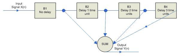
Figure 1: This figure shows the basics of an FIR filter. The input signal is sampled at varying times (though each time interval is equal), corresponding to each square. Each square also has a coefficient, A1, A2, A3, etc., that is the coefficient multiplied with each sample. The output of this particular filter is: Y(n)=B1*X(n) + B2*X(n-1) + B3*X(n-2) + B4*X(n-3)
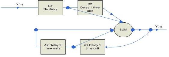
Figure 2: This figure shows the basics of an IIR filter. It is similar to an FIR filter except that previous outputs are “fed back” into the summation. The output of this particular filter is Y(n)=B1*X(n) + B2*X(n-1) + A1*Y(n-1) + A2*Y(n-2)
Different types of IIR filters have different frequency responses. For example, an Elliptic filter has a very sharp cutoff region but has large ripples in the passband region, while a Butterworth filter has no ripple but not as sharp a cutoff. After running the simulations in Matlab, using the GUI “fdatool,” we came to the conclusion that Butterworth filters give the best frequency responses for passing an instrument note. For example, a Chebyshev Type 2 filter will pass very little of an undesired notes frequency, but if your string is only slightly out of tune, then it may be blocked as well. Hence we decided that Butterworth filters gave the best trade off between blocking other notes and passing enough signal of the desired note.
There is also math involved with sound output. We use a method called Direct Digital Synthesis (DDS) in synthesizing the sound. The main formula being: increment = 68719*frequency, when the microcontroller is in fast PWM mode and we are setting OCR0=128 + sineTable[highbite]. Where sineTable is a length 256 array representing a sine wave. highbite is the upper bite of a variable called accumulator, and accumulator is a 4 byte variable that equals accumulator + increment. This leads us to derive that increment equals 2^32(# of bits in accumulator)*256(value of “Top Register” in fast PWM mode)*(1/clock_speed)*output frequency. We used a 16 MHz clock and hence calculate that increment = 68719*frequency. This is how we calculate the PWM output signal that corresponds to a particular frequency.
Logical Structure
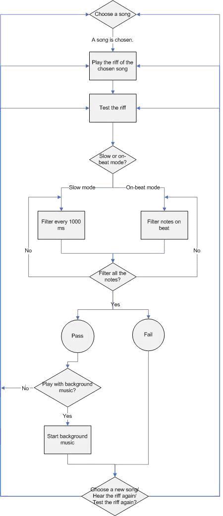
Figure 3: State Machine of the Program
Hardware/Software Tradeoffs
Choosing a Filter
As we mentioned in the Background Math part, different types of IIR filters have different frequency responses, but we chose to use the Butterworth IIR filter because it passes enough signal for the desired notes while blocking other notes that is suitable for filtering guitars or other string musical instruments.
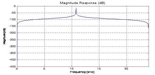
Figure 4: This figure shows the frequency response of a 2nd order IIR Chebyshev Type 2 filter using Matlab’s GUI “fdatool”. Notice the extremely narrow band pass region.
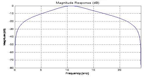
Figure 5: This figure shows the frequency response of a 2nd order IIR Butterworth filter using Matlab’s GUI “fdatool”. This has the same bandpass region as the Chebyshev Type 2 above. Notice the difference in bandpass region. A Butterworth still filters the undesired notes well enough to be effective, but at the same time, allows slightly out-of tune strings to be recognized.
User Interface
For the user interface, we chose to use hyperterm, which is on the computer screen, instead of using the combination of LCD and keypad. Even though the latter option seems to be more convenient because the size of the LCD and keypad is small, making the product portable, it is easier to see the notes on the hyperterm and type in the inputs using a computer keyboard. This way, the user can use a computer at home to run the program as well.
Standards
It conforms to the applicable standard of being able to use an RS-232 communication and using a quarter inch electric cable for sending voltage form the instrument to the circuit.
Patents/Copyrights
If we want to mass produce this design and sell it in the market, we will have to ask for the copyrights of the songs that will be in our products.
Program/Hardware Design
We use the STK500 board with the Atmel Mega 32 chip and a 5-volt DC power supply. To get the input from the musical instrument, we connected the instrument to port A.0 to the A/D converter, which later goes through the Butterworth IIR bandpass filter that detects if the user plays the right note. To receive the input from the user via hyperterm, we connected the RxD port to port D.0 of the MCU and to send the data from the MCU to the screen, such as displaying the notes, we connected the TxD port to port D.1. For the sound output, we send the PWM signal from port B.3 through a low pass filter connecting to the speakers.
We also had to build 2 circuits. One for filtering noises, biasing, and amplifying signals from the instruments and the other is for filtering the high frequency signal from port B.3 output that human cannot sense.
A mandolin, guitar, and other electric instruments tend to output a voltage on the order of plus and minus a few hundred millivolts. However, the ADC of an MCU only works on positive voltages in the range of 0-5 volts. Hence we need to bias up the signal 2.5 volts, and then amplify it. The 4.7?F capacitor acts as filter to help block 60 Hz noise, the two large and equal 100k? resistors bias the signal to 2.5 volts, and the LM 358 op-amp circuit shown below has unity gain at DC and a gain around R2/R1 at higher frequencies. This is easy to imagine because at DC the capacitor acts like an open source and hence the voltage at the output will equal the voltage at the input. At high frequencies the capacitor will have little effect and the gain will be approximately R2/R1.
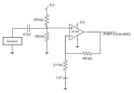
Figure 6: The circuit for the bandpass filtering of the signal from the instrument
The sound output from port B.3 also needs to be filtered. The low pass filter of this sound output to the speakers screen out high-frequency signals that human cannot hear. The specifications are as follow:
1) The resistance chosen is between 30 ? and 20 k?. The lower bound is set to make sure that not too much current is drawn into the port pin of the MCU, and the upper bound is set so that this resistance does not exceed the input resistance of the speakers.
2) The output period of the PWM is 256/(16MHz) = 16 microseconds. We want the time constant, RC, to be 10 times that of the PWM output, or 160 microseconds.
We decided to use R= 2 kOhm, and C= 100 nF. This gives us a time constant of 200 microseconds, which is about 160 microseconds.
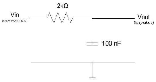
Figure 7: The circuit for lowpass filtering the sound to the speakers
The two circuits required for this project are not hard to build because we only need resistors, capacitors, an op-amp and a 5-volt power supply, which can easily be ordered from an electronic parts supplier.
The software setup for STK 500, in CodeVision, is for ATMega32 chip with a 16 MHz clock rate. We set (s)printf Features to long, width, precision so that it can display the correct values for the rms input from the instrument and other calculations from the filters, which is used for the purpose of testing the program. The other fields are left as default.
User Interface
The program consists of three main functions, which are outputting the riff of the songs, filtering the voltage input from the instrument and outputting the background music. The state machine is used to handle these tasks, according to Figure 3.
The three variable states are toriff, tofilter, and tobackground.
State 1: toriff
If the program is in this state, the synthesizing of the melody, which can be accessed through header files, will be generated until the ending time of the song. The purpose of sound synthesizing is so that the users know what the riff sounds like. We generate the sound by Direct Digital Synthesis (DDS) since it is an easy-to-implement method and we have done experiments with it before. We used and modified the DDS code from Cornell University professor Bruce Land. Before outputting the sound, we calculate the increment of the signal. As mentioned in the Background Math part of the High Level Design, the increment of the generated wave is increment = 2^32(# of bits in accumulator)*256(# of entries in sineTable)*(1/clock_speed)*output frequency = 68719*frequency, where the frequency is obtained from the look-up table in the program. accumulator is then incremented by increment in the interrupt. Right before the sound is outputted, we set accumulator, TCNT0, and OCR0 to 0 to stop Timer0 counter and phase lock the sine wave generation. Also, TCCR0 is set to 0b01101001 turn on PWM. Bit 6 and 3 is set to 11 for fast PWM and update OCR0 at top. Bit 5 and 4 is set to 10 to clear OC0 on compare match and set OC0 at top. Bit [2:0] is set to 001 for no prescaling. By experimenting, we found that running 1 interrupt at a time when generating PWM signal gave better-quality sound. Since we have two interrupts running, we turn off Timer1 Overflow ISR by setting TIMSK to 0b00000001, which allows only Timer 0 Overflow ISR to run. We chose the prescalar of the amplitude of the wave to be amp = 7. This number provides smooth-enough wave signals. We start ramping up and down the amplitude to synthesize the sound according to the frequency of the notes. This keeps going in a loop until we have reached the end time of the riff. Then, we turned off the PWM.
State 2: tofilter
Tofilter is the state when the program starts taking the input from the instruments and passes it through a bandpass filter. The detail of how the filter works is explained in the filter code section of the Software Design. Similar to the PWM output part, we experimented and found that the filter did not work when both the Timer0 Overflow and Timer1 Overflow ISRs are on. As a result, we turn off the Timer0 overflow ISR and let the Timer1 Overflow ISR to run by setting TIMSK = 0b00000100. In this state, the user can choose to test the riff in a slow mode or an on-beat mode. The slow mode provides a consistent rhythm for the riff, regardless of how fast the actual beats are, which is easier to play. We chose the time between notes to be approximately 1000 milliseconds because it is long enough for the user to follow, and to implement this, we use delay_ms(1000). For the on-beat mode, the time between each note is about the actual time between the notes, delay_ms(note duration). This time is not exact because we have to take into account of the delay from the function call to filter subroutine. We tested how long and how many cycles it took to do the calculation for the filters by turning on Timer 2, and setting TCNT2 = 0 at the beginning of the filter subroutine with a prescalar of 8 (TCCR2 = 8) and set the prescalar to 0 at the end of the subroutine. Then, look at the value of TCNT2 and calculate the period and cycles. After thoroughly testing, we found that it took an average of 4 milliseconds to execute the filter subroutine. Even though this time delay is unnoticeable to human, if there are a big number of notes in the riff, the delay can add up and cause the total time to be slightly off. To keep the total time running the filter as close to the real total time as possible, we subtract 4 from the desired delay amount, delay_ms(note duration). Also, we had to take into account of the delay from human reaction. When the note is displayed on the screen, human reaction delay can cause the user to play the instrument a little later than they suppose to do. Thus, we delay by 100 milliseconds before calling the filter subroutine and we also subtract this amount from delay_ms(note duration). Note that we did not subtract any number from delay_ms(1000) because it will still provide a constant amount of time between notes. In the PWM outputting part, we determine when to stop the sound by checking if the total time it has been outputting the sound is greater than the total time of the riff. However, in this part, since the filtering can cause a small amount of delay in the program, we check the number of notes that has been filtering instead. This way the filtering of the note does not stop before it gets to the end of the riff.
State 3: tobackground
This state is similar to the toriff part because both of these states synthesize the sound using the DDS method. However, the background music is generally lower and gets repeatedly played. Thus, we do not need to set up header files for storing the data of the background music. While outputting the music, we also turn off Timer 1 Overflow ISR as and use Timer0 Overflow Interrupt as in the toriff state.
Handling the Data for the Song
We designed the program such that each note was independent of the other, which was less complicated when outputting the sound (This idea was suggested by our TA, Idan Beck). To make each note independent from each other, we stored both the starting and ending time and the length of the notes, which requires more storage space than just storing the length of the notes for the other implementation. However, if we design each note to be dependent on the other and if the timing of one note w off, the timing for the rest of the notes in the riff will be affected as well, which can cause a lot of problem.
Also, to make it easier to edit the file in the future, we include the riff and octave arrays, which are used for looking up the frequencies when synthesizing the sound. The tradeoffs are that the way we implemented requires large storage spaces, and we decided to use header files to store these array values. The header files keep the program organized and easy to access. Note that when the files get bigger, it is important to keep track of the index because, once the index of notes is wrong, it is hard to find where the wrong index is.
The header files for the song include
- song4.h for storing the riff and octave, used for looking up the frequencies
- timesong.h storing the length of each note used for calculating the starting time and finishing time for the notes.
- test.h storing the characters that can be displayed on the hyperterm before outputting the riff music and while users are testing the riff.
We use printf and scanf to handle the storing and printing of the data. However, these two functions block the program. When we run the filter, we use gets_int() and puts_int(), which was from professor Bruce Land’s code. This is the method that does non-blocking printing and keyboard check.
Filter
We set Timer 1 interrupt to run at 7812 Hz. Inside this interrupt is the code to obtain the ADC samples. By varying the value of samplef, we can vary the rate at which the sample are put into the array, and hence vary the rate of the sampling frequency.
The IIR2 assembly code was designed by Cornell University professor Bruce Land. It takes an input, x(n) and calculates an output y(n)=a1*y(n-1)+a2*y(n-2)+b1*x(n)+b2*x(n-2)+b3*x(n-3). The numbers must be converted to fixed point before they can be used in the assembly code and are converted back to floating point again before being used in the rest of the code. Filtering is already very cycle intensive and running filters on floating point numbers would be a waste of cycles. It would be tedious to go through each line in the assembly filter code but it is important to notice that the inputted “a’s” are negated from the design calculation to save cycles and the assembly code uses functions native to the AVR instruction set. Examples of these include muls, mulsu, and the multiply and accumulate operation, these functions are described in the Atmel application note AVR 201.
The filter code is called in the main program when it is time to check if the user is a playing a note correctly. The filter code runs three filters in parallel on the current input array. One filter contains the coefficients to calculate the frequency of the note one lower than desired, one filter contains the coefficients to calculate the frequency of the desired note, and another filter contains the coefficients to calculate the frequency of the note one higher than the desired note. Each filter then sums the absolute values of the amplitude of each output sample, y(n). Finally these summations, which are called rmsout in the code and will be called rmsout throughout the explanation, are compared to determine which note was played.
There were two tricky things about software design when it came to the filters. One thing we had to worry about was that the output rmsout of a signal after going through the filter was always a different value, even if someone kept playing the same note. This is because the output rmsout is dependent on several factors, including how hard the string was plucked, how much the person “bent” the string, how much noise there was, etc. If the output rmsout of a filter is always different, the MCU cannot detect if the right note is being played. To solve this problem, we run three filters at once. One filter band-passes one note lower than the desired note, another filter band-passes one note higher than the desired note, and the third filter band-passes for the desired note. The input signal is sent into all three filters, and each filter produces an output signal with a different rmsout. The rmsout of all three outputs are compared to see if the user played the right note, too low, or too high. If the user plays two notes too low or two notes too high, it will still output “low” and “high” respectively. The advantage of this is that it no longer depends on how hard the user plays the note or how noisy the environment is, all that matters is the relative rmsout.
The second tricky thing we had to worry about was choosing an appropriate sampling rate. If the sampling rate is too slow, less than half of the frequency of the fastest signal according to the Shannon-Nyquist theorem, then there will be a phenomenon known as aliasing. If the sampling rate is too fast, then it becomes extremely hard to filter because filters act on normalized frequency, f/fs, where fs is the sampling frequency and f is the frequency of the signal. Hence a particular band pass region (f1-f2)/fs becomes harder and harder to filter as fs increases. The solution to this problem, which must be partially credited to Professor Hutchins of Cornell University, is by changing fs dependent on what signal we are trying to filter. We change fs by changing how often our array is set equal to the value in the ADC. This is the whole point of the if (sample ==samplef) line in the Timer 1 interrupt. This enables us to set a sampling rate equal to 7812 Hz/samplef, 7812 Hz is the frequency at which the Timer 1 Interrupt is called. So if we want to sample at 651 Hz, we set samplef =12 because 7812/12 = 651.
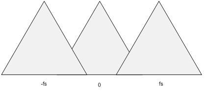
Figure 8: The aliasing of the input signals when the sampling rate is less than half of the frequency of the fastest signal.
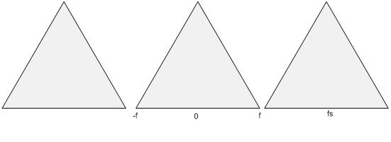
Figure 9: This is a graph showing the frequency domain of a signal. As can be seen, there will be overlap unless fs is at least twice f, the highest frequency component of the signal.
Things Tried that Did not Work
We tried to do DDS while filtering. We wanted to perform this so that one can practice while listening to the background music. However, it did not work because both filtering and DDS are very cycle intensive operations and it was extremely difficult to get both working at the same time.
Results of the Design
Speed of Execution
The filter code took 3(number of filters)*180 (cycles/filter)*118(size of array we filtered on)=63720 cycles. This corresponds to 63720 cycles /(16 MHz)=3.9825 ms, well below human reaction time.
Accuracy
Every note has been tested individually and thoroughly. The filters were not 100% ideal to the Matlab simulations. However, they were close enough for our purposes of determining which note was being played. The only time our code would not filter a signal correctly was when an open string on a guitar was plucked rather hard. Then the voltage would clip on the op-amp at 5 volts and it would have almost square-wave like features that include an unpredictable frequency response. Besides this one exception, if a note is played right, it extremely rarely outputted that it was played wrong.
Also, there is the unstoppable effect of aliasing. Since we lowered the sampling rate to better filter the right note, we also created aliasing if someone plays a note that is song that it is >1/2 fs. These aliased notes give random results as to which note was played. However, if someone keeps missing the notes by so much that there is aliasing, than just by pure probability he/she will not get enough notes correct to move on to the round that turns on back ground music.
Similarly, if someone plays a note significantly lower than the ones coded for, the output of the filter code is rather unpredictable; however it is not from aliasing. It is because that note is in such a low dB range of all three filters that it is either a) impossible to tell which note it is closest to, or b) it’s 2nd and 3rd harmonics start having a larger effect than the actual note. However, similar to the high pitched notes, if someone keeps missing the notes by so much that there is aliasing, then just by pure probability he/she will not get enough notes correct to move on to the round that turns on back ground music.
Safety
At the beginning of the game, a statement is outputted telling the player to be careful of his/her surroundings and that moving around can lead to accidents.
Interference
60 Hz noise was filtered out using the noise reduction circuit right before the bias circuit. We connected the musical instrument to the MCU electrically so that audio noise would not be a concern. Extremely high frequency noise was never a serious problem with our circuit. Comparing the output of three filters at once, as described in the “tricky” section, helped limit the effect of noise.
Usability
The ability to play the guitar well is an acquired skill that is developed with practice. We realized this and hence have a beginner mode that enables people to start at a very basic level with filters that are called very slowly. If someone can not physically play a guitar, mandolin, or other stringed instrument, than unfortunately they will not be able to play Legend Maker.
Expectations and if you could do it again
We were hoping to build something that could have the user program in a riff, program in back ground music, and have the filter running at the same time as the background music. Unfortunately, it was exceedingly difficult to output music and filter notes at the same time due to timing and other factors. We also abandoned the idea of the user programming riffs because the UI is already very complicated.
If we could do it again we would use a DSP chip so that the MCU won’t be used for filtering but could be used for other applications. The DSP chip would also be used to filter for chords.
Ethics
IEEE Code of Ethics
We, the members of the IEEE, in recognition of the importance of our technologies in affecting the quality of life throughout the world, and in accepting a personal obligation to our profession, its members and the communities we serve, do hereby commit ourselves to the highest ethical and professional conduct and agree:
1. to accept responsibility in making decisions consistent with the safety, health and welfare of the public, and to disclose promptly factors that might endanger the public or the environment;
2. to avoid real or perceived conflicts of interest whenever possible, and to disclose them to affected parties when they do exist;
3. to be honest and realistic in stating claims or estimates based on available data;
4. to reject bribery in all its forms;
5. to improve the understanding of technology, its appropriate application, and potential consequences;
6. to maintain and improve our technical competence and to undertake technological tasks for others only if qualified by training or experience, or after full disclosure of pertinent limitations;
7. to seek, accept, and offer honest criticism of technical work, to acknowledge and correct errors, and to credit properly the contributions of others;
8. to treat fairly all persons regardless of such factors as race, religion, gender, disability, age, or national origin;
9. to avoid injuring others, their property, reputation, or employment by false or malicious action;
10. to assist colleagues and co-workers in their professional development and to support them in following this code of ethics.
We worked very hard and did our best throughout the development of this project to fulfill the IEEE code of Ethics. For example, we do not try to “cover it up” that we used Bruce Land’s IIR2 assembly filter code and say it is our own. We openly admit that this game still has certain flaws, like if an open string is played on a guitar with a certain force, the program may not detect the note correctly. This project has greatly improved our technical competence has it has taught us digital filtering, basic circuit design, basic database programming, and the relationship between music and electronics. We are more than willing to assist any of our colleagues who need the knowledge that we have obtained through making this game, regardless of their race, religion, gender, etc. The developers of this game are of different race, gender, and national origin. Yet both worked equally hard and together to build this product. Finally, we are open to criticism, it is through constructive criticism that we may improve. We hope to hear from our peers and from users of the game about what they liked, so we know to do more of it, and what they disliked, so we know what to fix.
Appendix A: Photos
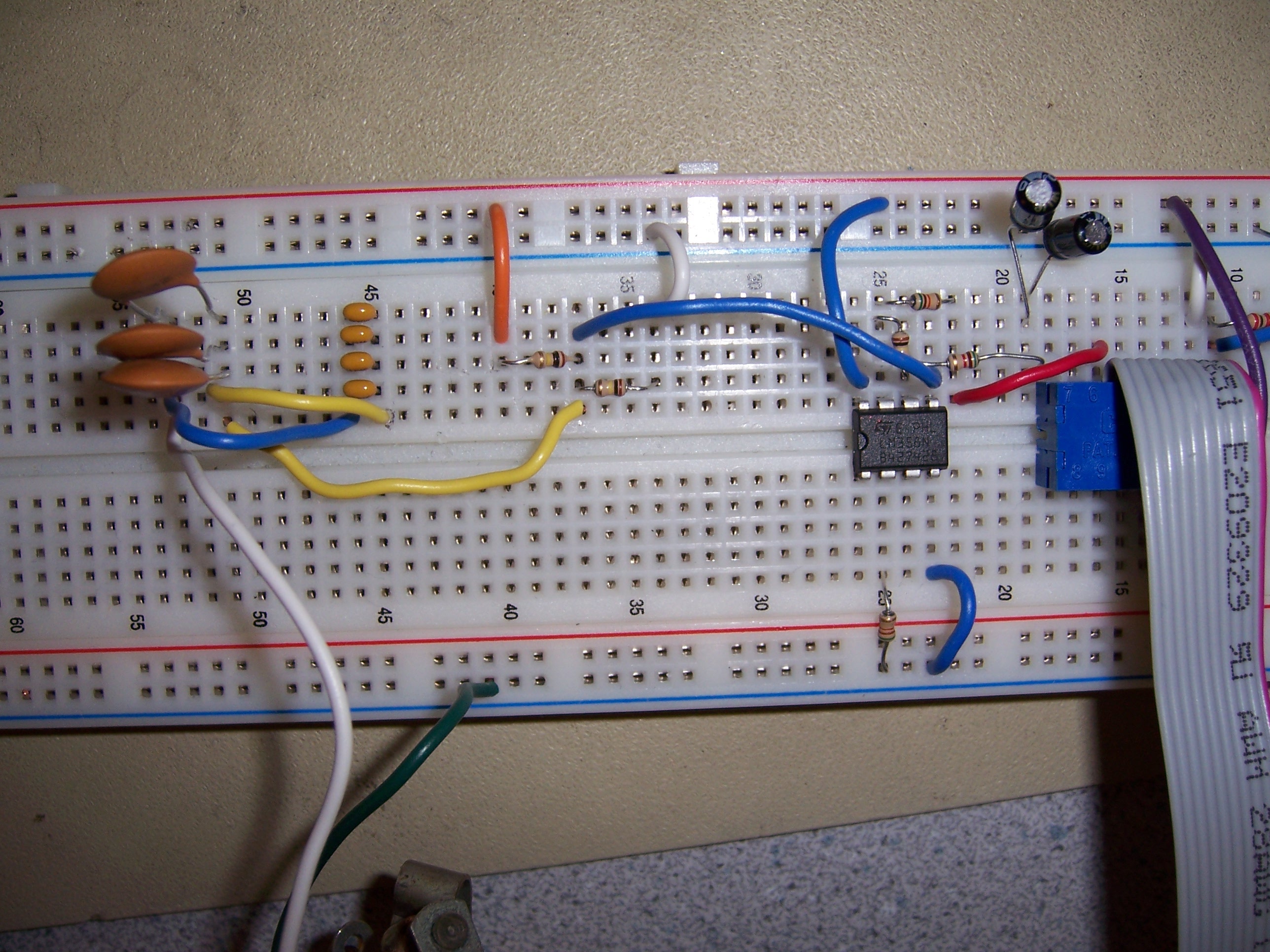
Figure 10: The amplifying circuit of the guitar input signal and the lowpass filter to the speakers.
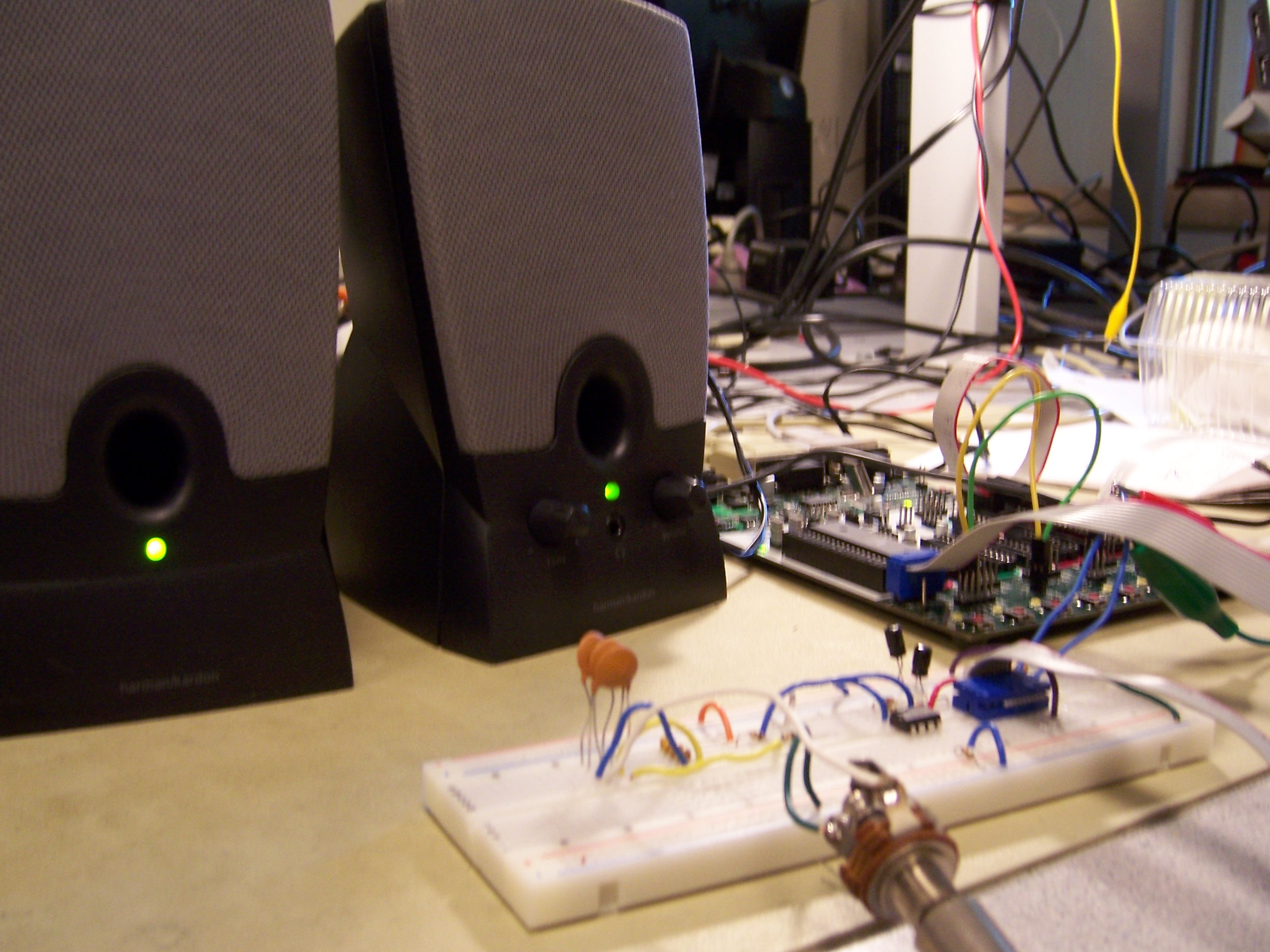
Figure 11: The set up of Legend Maker
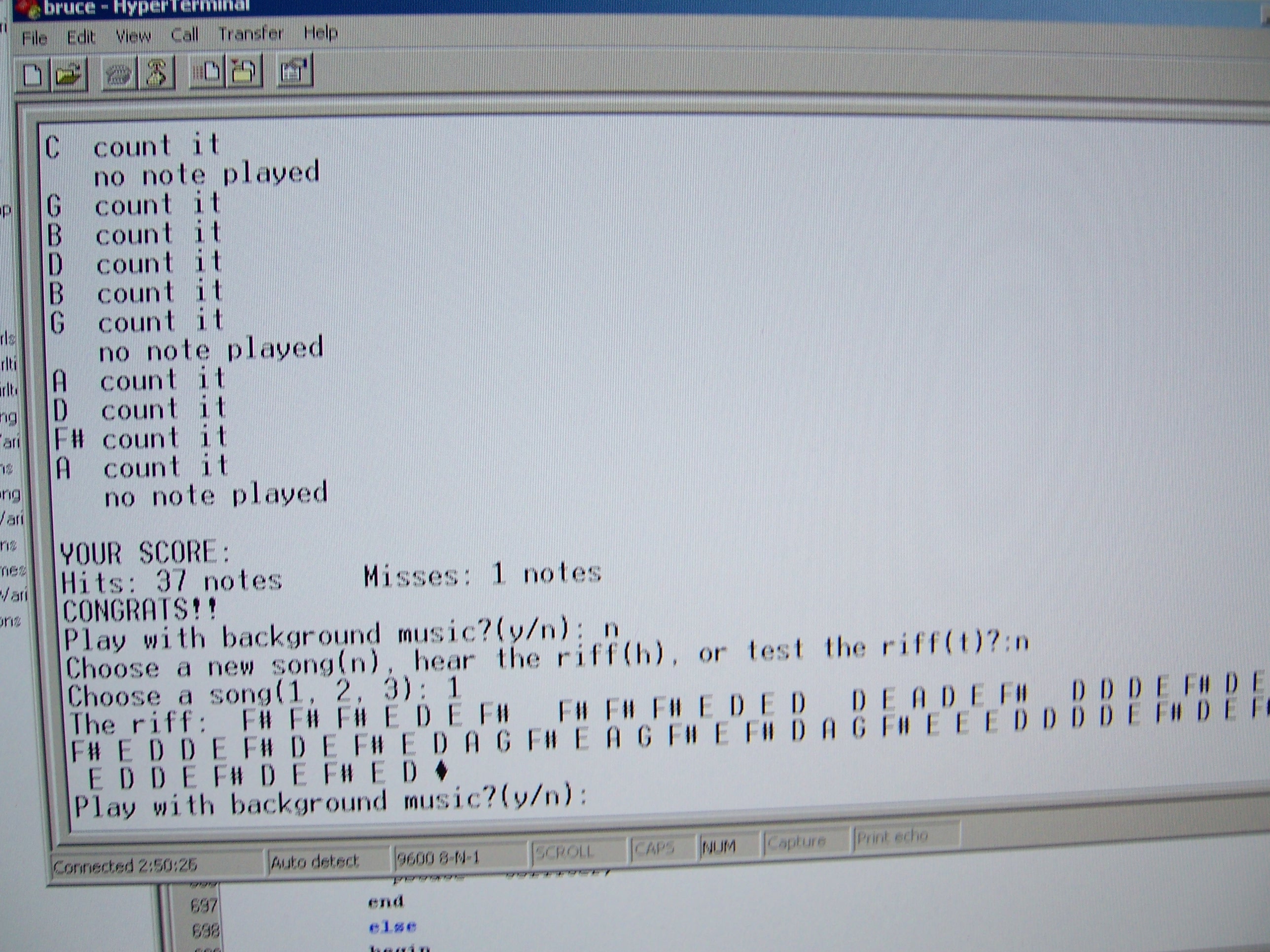
Figure 12: The result on hyperterm
Appendix B: Schematics
See Figure 6 and 7 for the schematics.
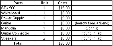
Appendix C: Cost Details
Appendix D: Work Distribution
Researching - John and Thidanun
Hardware Design - John and Thidanun
Soldering - John
Software (User Interface) - Thidanun
Software (Filter) - John
Software (DDS) - John and Thidanun
Testing - John and Thidanun
Code
The main C file: final.c
Song 1(“With or Without You”) header files: notes, time, note display
Song 2(“Brown Eyed Girl”) header files: notes, time, note display
References
Code from Prof. Land