Rhythm Ring
Interactive Rhythm Sequencer
|
| An ECE 476 Final Project by Brian Yung (bmy5) & Hanson Jiang (hcj4) |
I. Introduction
The Rhythm Ring interactive rhythm sequencer is an engaging musical device that enables the user to create a plethora of rhythms and beat patterns with the touch of their own fingers.
Besides being fun to play with, the Rhythm Ring provides a tangible method of arranging a musical rhythm. In our design, the user can arrange beats and modify them in real time by moving steel ball bearings between holes—a physical representation of notes on a musical staff. The Rhythm Ring continuously loops up to three tracks, each with its own voice. A central ring of LEDs provide the user with live feedback for current "playhead" position, and bright LEDs pulse when a note is played due to a detected bearing. The three tracks allow the playback of three different percussion sounds: snare, hi-hat, and bass drum.
We designed and built this device as a five-week final project for ECE 476 at Cornell University.
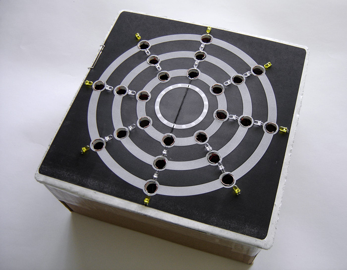
Fig. 1: The Rhythm Ring Unit
II. High Level Design
Rationale and Inspiration
The goal of this project is to provide a tangible means of arranging a continuous, dynamic rhythm. An arranger no longer needs to play a traditional musical instrument or use PC-based music software to experiment with rhythms—our device can encourage experimentation through direct, physical manipulation. The arranger can also speed up or slow down the tempo by pressing control buttons on the unit.
The inspiration for this project derives from our mutual interest in music and rhythm. Hanson plays electric guitar, baritone horn, and drums, while Brian plays the acoustic guitar and practices step dance. Because of our enjoyment of and curiosity for arranging and playing music, we decided to design a musical device as our final project. Another source of inspiration was the design and implementation of a more sophisticated sequencer called the BeatBearing, created by Mr. Peter Bennett at the Sonic Arts Research Centre at Queens University Belfast. He is an innovator of interactive devices and has been promoting the concept of the Tangible User Interface (TUI).
Concept
A platform contains three concentric circular tracks, with each track representing a different synthesized sound. Ball bearings can be placed in eight equally-spaced holes on each track. An embedded sensor network detects if ball bearings are present in any of the 24 holes (eight holes per track). The sensor network is composed of a series of wire pairs. Each hole has one wire along the edge of each half the circle. When a conductive steel ball bearing is placed in a hole, it connects the two wires around the hole’s rim.
When the device is turned on, it begins at a pre-defined position on the circle and sweeps along the tracks in a circular motion. As it sweeps around the circle, it keeps track of the current position along the circumference of the circle. In the center of the board, there are 32 green LEDs (later reduced to 16) arranged in a circle with only one of the LEDs lit at a time, showing the current position.
Since the holes are equally spaced throughout the circular tracks, the position of each hole can be calculated by dividing the length of the track into eight segments. We can then define these positions and compare them with the current position counter in the program. When the program reaches one of the eight predefined positions, it will check for the presence of a ball bearing in any of the three tracks at that position. If the program detects a ball bearing in a particular track, it will play the corresponding sound and flash the LED near the ball bearing. If multiple tracks have ball bearings at that position, it will superimpose the sounds by summing their audio samples. When the program reaches the original position on the circle at which it began, it repeats the loop and continues operating until the device is turned off or reset.
Background Mathematics
The bulk of the mathematics necessary for this project involves audio synthesis and signal processing. The rest of the mathematics used consist of simple algebraic computations and timing calculations for Timer 0 and Timer 2. We describe specific calculations for Timer 0 and Timer 2 configurations in the Program Design section.
Audio Synthesis of Percussion Sounds
We began by looking at the spectral content of some recorded percussion sounds from Apple's GarageBand creative music application and then Fourier-analyzing them in the open-source audio editor Audacity. Unlike plucked strings, percussion instruments do not have a simple wave-like form. Drum sounds typically contain many frequencies, as shown by the peaks in the frequency spectrum highlighted with red lines in the plot below. This implies that such a sound could be synthesized using multiple sinusoids.
Fig. 2: Frequency Spectrum of a Hi-hat from GarageBand, Plotted in Audacity
Looking at the time domain of the audio signal, we see an exponential decay until the sound dies out completely and becomes silent. With percussion sounds, these decays tend to be faster and less regular than those of plucked strings. Additionally, percussion sounds tend to have a large “attack,” followed by a fast decay at the beginning and then a slower decay after the beginning portion of the signal.
Fig. 3: Time-domain Waveform of Bass Drum from GarageBand, Plotted in Audacity
After weeks of experimentation and analysis, we came to the conclusion that the Karplus-Strong (KS) algorithm and Direct Digital Synthesis (DDS) may require too much computation time to produce even moderate-quality percussion sounds within the roughly 720 cycles between each 22.050 kHz sampling deadline. We initially planned to use a 44.100 kHz sampling rate, since that would allow us to reproduce up to 22.050 kHz frequencies (the Nyquist limit for perfect reconstruction), but we scaled back to a sampling rate of 22.050 kHz in order to free up processor cycles for all the other computations necessary for our project. In addition to being set back by the limited computing power of our MCU, the acoustic theory behind the KS method seemed to be beyond the grasp of our understanding as we struggled to produce a range of good-quality percussion sounds.
Instead, we decided to take what we learned from our experimentation with the KS algorithm and DDS to develop a simpler audio generation method (avoiding floating point operations and division) that can produce an acceptable-quality percussion sound. By summing sinusoids of various frequencies close to the ones found in the recorded-instrument frequency spectrums, and by using various fast and slow decay factors, we generated MATLAB code to generate audio waves suitable for sampling at 22.050 kHz. The following is an excerpt from our bass drum sound synthesis MATLAB method:
n = 4000;
for j=1:n/2
slowdecay(j) = 1-j/(n/2);
end
for j=1:n/200
fastdecay(j) = 1-j/(n/200);
end
for j=1:n
bass[j] = slowdecay(j)*(sin(0.018*j) + sin(0.022*j)) + fastdecay(j)*(sin(1.2*j) + sin(5.5*j)
end
We then sum multiple sinusoids together using the equation: sin((f/fs)n + 2π), where f is the frequency of the sinusoid and fs is the sampling frequency. Next, we apply decay factors by setting up an exponential multiplier: multiplier = 1 - (1/b), where b is larger than 1 but smaller than the sample size.
To further reduce the audio output routine resource footprint, we decided to pre-calculate 4000-sample wave lookup tables for each instrument using code similar that of the excerpt above (full MATLAB code for table generation is in the Appendix). We defined each sample table as an array of unsigned chars and stored each array in flash memory, filling 12kB of memory on top of our program code. Since our program only occupies about 4kB without the lookup tables, we are not in danger of hitting the 32kB flash memory limit.
We also considered the math necessary to convert these digital samples to an analog audio signal. Since these values are stored as lookup tables in the program, we first set them as unsigned chars ranging from 0-255 with a base level of 127. We then feed the samples into the DAC, which converts them to a positive analog current. Finally, a large capacitor removes the DC component resulting from the offset of 127, giving us an equal positive- and negative-range audio signal.
Another consideration was the possibility of clipping due to superimposing up to three sound samples at a time (if all three tracks have ball bearings present at one position). To avoid distortion due to overflow in this situation, we divide all samples in the lookup tables by 4 by shifting right by 2 bits. Since shifting right by 2 is much faster than dividing a value by 3, we accept the small loss in dynamic range in exchange for reduced MCU overhead.
Standards
The primary standard to which we adhered involves the protection of users from eye safety hazards. The IEC 825-1 (International Electromechanical Commission) "Eye Safety Classification of Some Consumer Products" describes specifications for laser and LED emission safety requirements to minimize risk of retinal damage. The wavelength, exposure duration, pulse characteristics, distance from the eye, and image size of any laser or LED light source are all factors that can affect the safety of a consumer product that uses such components. Because we use superbright LEDs in our project, we complied with the safety standards addressed in IEC 825-1 while developing the code and determining the LED placement. We reduced the intensity of and exposure to the LEDs by either diffusing them through a medium in the case of the playhead LEDs (although these LEDs emit a very safe amount of light), or by pointing them away from the user in the case of the superbright bearing LEDs.
Relevant Existing Patents, Copyrights and Trademarks
The concept of this project derives from an innovative project called BeatBearing, designed and created by Peter Bennett, a Ph.D. student working in the Sonic Arts Research Centre at Queens University Belfast. The project uses a tangible user interface to implement a rhythmic sequencer.
Charles Allen from Maxim-IC discovered the technique of Charlieplexing to specifically drive a large number of LEDs using relatively few input/output pins on a microcontroller. The technique is formally documented on Application Note 1880 (AN1880) from Maxim-IC.
III. Design Implementation
Hardware Design
Platform (Human Interface Board) Construction
The Rhythm Ring's physical interface platform is based on an Elmer's one-sided adhesive foamcore board that measures 11” x 11” x 0.25” (cut with an X-acto model-building saw). We designed the layout of the tracks and the other components using Adobe Illustrator and printed the layout to use as a temporary construction mask by taping it to one side of the board.
After applying the temporary mask, we cut out the holes on the tracks with a Swiss Army knife to make coarse cuts, and a Dremel tool to sand the rim of the circle. The playhead holes (the 16 smaller holes in the innermost ring) were drilled using a small drill bit on the Dremel. We drilled these holes through the foamcore, but unlike the bearing holes, we left the playhead LED holes covered by our final decal. This allowed us to diffuse the LEDs by placing them right underneath the printed decal so that the playhead LEDs would not compete for attention with the track LEDs.
Once all holes were drilled, we printed and applied our final decal. We carefully cut the bearing holes out of the paper with a Swiss Army knife.
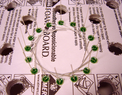
Fig. 4: Playhead LED Initial Assembly
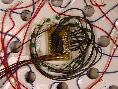
Fig. 5: Playhead LEDs with 16:1 Mux
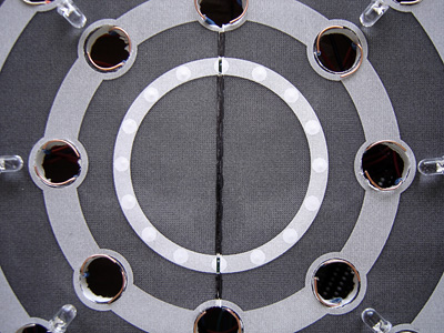
Fig. 6: Playhead LEDs, Top View

Fig. 7: Final Human Interface Board Decal
Sensor and LED Networks
With the track holes drilled, two exposed wires were placed in each hole to construct the sensor network. The end of one wire is curled along the edge of one half of the hole, while the end of the other wire is curled along the other half. These wires were placed in all 24 bearing holes (8 per track). These sensors must allow the microcontroller to detect if a ball bearing is present. To do this, we use the 0.75"-diameter steel ball bearings to connect the two exposed wires in each hole, pulling the voltage at the tapped junction up to Vcc. When no ball is present, a 330Ω resistor pulls the junction down to ground. Each sensor junction is connected to one input of an 8:1 mux (we use one mux per track). To detect a bearing at a certain location, we use the mux to select that particular sensor and send the voltage at that point to an input pin on the MCU. Charlieplexing allows N pins to selectively drive N(N-1) LEDs.
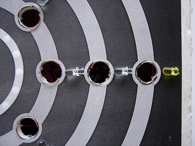
Fig. 8: One Column of Bearing Sensors and Superbright LEDs
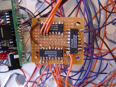
Fig. 10: The Three 8:1 Bearing Sensor Muxes
Charlieplexing
With a limited number of input/output pins on the ATMega32, our design leverages a circuit technique called Charlieplexing. Charlieplexing allows a network of LEDs to be driven using fewer I/O pins than if they were directly connected one-to-one with each pin. The key concept in Charlieplexing is utilizing the high impedance state of our MCU's tri-state pins. On the ATMega32, an input/output pin can be switched to high impedance mode by setting it to an input.
| Active LED |
PIN A |
PIN B |
PIN C |
PIN D |
| LED1 |
0 |
1 |
Z |
Z |
| LED2 |
0 |
Z |
1 |
Z |
| LED3 |
0 |
Z |
Z |
1 |
| LED4 |
1 |
0 |
Z |
Z |
| LED5 |
Z |
0 |
1 |
Z |
| LED6 |
Z |
0 |
1 |
Z |
| LED7 |
1 |
Z |
0 |
Z |
| LED8 |
Z |
1 |
0 |
Z |
| LED9 (Unused) |
Z |
Z |
0 |
1 |
Table 1: Truth table for LEDs using Charlieplexing with 4 pins.
With Charlieplexing, 4 pins can be used to individually turn on a maximum of 9 LEDs. In our implementation, we use four pins to control only eight LEDs (four pins control one of three 8-LED tracks). Charlieplexing works in this implementation by setting only one of the four pins high so that only one of the nine LEDs turn on. To implement our track LEDs, we make three Charlieplexed LED networks and we allow only one LED to turn on per track. Figure 19 in the Appendix shows the three networks connected to the ATMega32 ports.
For example, if we want LED1 to turn on, the program will set PINA to output low, PINB to output high, and PIN C and D to inputs (high impedance). As one can determine from Figure 19, LED1 will get a positive voltage across it, turning it on. All of the other LEDs will have either a voltage of ≤0V across them or a pin at high impedance, causing them to remain off.
We calculated the resistor values using the typical forward voltage drop and current handling specifications from the manufacturer. For example, the blue superbright LEDs have a maximum reverse voltage of 5V (perfect for our application), a typical forward voltage drop of 4V, and a continuous current rating of 20mA. Since we are supplying 5V to the LEDs, we calculate the necessary drain resistance using Ohm's law: (5V - 4V)/20mA = 50Ω. We use a 75Ω resistor since they are readily available and using a higher drain resistance is safe (the LED will simply run at less-than-maximum brightness, which is acceptable and possibly safer for superbright LEDs).
Digital-to-Analog Converter and Audio Output
Since the ATMega32 does not have an on-board digital-to-analog converter (DAC), we used an 8-bit parallel-input DAC (National Semiconductor DAC0808) from the ECE 476 Digital Lab's stock. The DAC takes in 8-bit values from an output port (PORTA in our program) for conversion to an analog current. We give the DAC0808 a Vref+ and Vcc of 5V, and a VEE of 0V. We connected the DAC's output to a simple high-pass filter that employs a 330 µF electrolytic capacitor and the inherent resistance of the connected speakers or amplifier (typically in the range of several kΩ). This removes the DC offset that we introduce by sending only values from 0-255 to the DAC input (resulting in only positive output current and voltage). The cutoff frequency of this high-pass filter is approximately 0.02 Hz. Since the DAC specifications report a relatively stable output current of 2 mA, we added a 1kΩ load resistor between the capacitor's cathode and ground in order to provide a ±2V audio output swing. The analog output signal is sent to an audio jack, which the user can connect to any speaker system with a standard ⅛" audio plug.
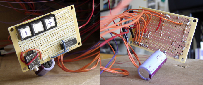
Fig. 11: DAC, Audio Output, and Control Button Board (Front and Back)
Discarded Attempts and Learning Experiences
As mentioned in the conclusion, we successfully implemented most of the features that we envisioned at the beginning. The only feature that has significant room for improvement is audio quality. At the beginning, we sought to use the Karplus-Strong algorithm, which is known for simplicity in implementation while generating very realistic sounds. However, when we tried to implement the algorithm in MATLAB, we could not produce a good range of percussion instrument sounds. We were able to make some realistic hi-hat variants, but we experienced great difficulty while trying to make snare drum and bass drum sounds. We spent approximately two weeks going through the theory involved and banded waveguide technique, but implementation quickly grew complicated and messy. Therefore we chose to abandon the algorithm due to our lack of knowledge in acoustics and we developed a much simpler method of generating sound samples. Although good plucked-string sounds are very simple using the Karplus-Strong algorithm, percussion sounds are more challenging. Some students in our class were trying to do the same thing and also expressed frustration with obtaining the sounds they wanted.
Program Design
Header Files
We use the following common header files:
- Mega32.h
- stdio.h
- stdlib.h
- math.h
We generated the following percussion sample tables in MATLAB (code and waveforms included in the Appendix), converted them to comma-separated variable format, and then made them into header files:
- snaretbl.h
- hihattbl.h
- basstbl.h
Main Routine Operation
The main routine handles the current track position. Timer 0 is configured to run at 250 kHz (prescaler of 64) and set to compare match (CTC) mode with OCR0 set to 249. This sets the Timer 0 Output Compare ISR to fire every 1 ms. Timer 0 ISR decrements a track timer until it reaches zero, and then resets the track timer. When the track timer reaches zero, it increments the program's global x-position. Since there are 8 beat slots for each track, we determine our place in each track with a base-32 x-position counter (each of the 8 sound beats is followed by 3 "silent beats"). We originally designed our program for a 32-LED playhead ring, but due to the un-solderable density of 32:1 muxes, we decided to reduce the number of playhead LEDs to 16. The base-32 x-position counter could be reduced to base-16, but we decided not to change it since it didn't affect operation.
Secondly, the main routine determines when to trigger the superbright beat LEDs and when to begin playing sound. It determines whether or not one of the 8 beats has been reached by checking if the current x-position modulo 4 equals zero, which occurs every fourth x-position out of 32. When the modulo result is zero, the program will trigger the subroutines to flash and dim the track LEDs and to enable sound output for tracks that have a ball bearing in the current x-position. The program then reads the ball bearing sensors in the next column and stores the results to the global bearing table.
Playhead LEDs
The playhead LED ring consists of 16 common 5mm green LEDs arranged in a circle at the center of the board. We drive these LEDs one at a time using a 16:1 mux from Intersil. Since only one LED will be on at a time, we can tie all 16 LED cathodes together and connect them to ground through a single 330Ω resistor. The 16:1 mux takes 4 control lines from the MCU and delivers 5V to any of the 16 LEDs depending on the half-byte control input. A subroutine sets these control bits at every other base-32 x-position (since we have only 16 playhead LEDs). A switch statement consisting of cases for every other x-position value sets the necessary PORT outputs.
Reading Bearing Sensors
Each track has 8 sensors which need to be read one at a time. Therefore we have three 8:1 muxes (one per track) which all receive the same 3 control bits from the MCU, since we read one column at a time. Each of the 8 mux inputs is connected to the junction between a reader wire and a 330Ω resistor tied to ground. A steel ball bearing will raise the voltage at the reading junction to 5V, which the 8:1 mux connects to one of three track-reading pins on the MCU. The program reads one column ahead of the current one and stores the state of that sensor (either 1 or 0) in the bearing table for playback on the next beat.
Dimming LEDs
Each of the 24 superbright LEDs illuminates and then dims when a bearing is present at the corresponding hole and the playhead reaches the corresponding column. In order to control the perceived brightness of an LED, we leverage a shortening duty cycle method (effectively pulse width modulation). An int provides 16 bits which we can use to provide 16 levels of brightness ranging from completely on to completely off. At the beginning of an LED illumination, we initialize the duty cycle to full on by setting all 16 bits high. The program reads each bit successively and calls set_led() to turn the appropriate LED either on or off (a zero bit in the duty cycle register translates to off). By switching the LED on or off very rapidly (close to or faster than the human eye's integration period), we can make the LED appear to glow steadily at a certain brightness.
After turning an LED on and off at a certain duty cycle several times, we shift a single zero into the duty cycle and repeat the output loop. We must use each duty cycle several times (about 20 or more times) since the whole process occurs very quickly and the LED would appear to simply turn on and off if we did not repeat the output of a single duty cycle multiple times. We can vary the number of loops per duty cycle in order to accommodate different tempos. Faster tempos will require faster dimming in order to fit an LED illumination inside one beat period. Slower tempos afford slower dimming, which makes the dimming effect more noticeable.
Audio Output
As mentioned earlier, we store pre-generated percussion audio samples in three header files. The program loads the 4000-char arrays in snaretbl.h, hihattbl.h, and basstbl.h into flash memory. On the ATMega32, we configured Timer 2 to run at 2 MHz (prescaler of 8) and we set CTC mode with OCR2 set to 90. This configures the Timer 2 Output Compare ISR to fire every 45 µs, or at a frequency very close to 22.050 kHz. With the interrupt set at this rate, the program must send out one 8-bit audio sample every time the interrupt fires as long as a bearing is present in the current column.
When the playhead reaches a column of track holes, the program resets a sample counter to zero and asserts a flag to enable sound computations in the Timer 2 Output Compare ISR. The ISR clears an 8-bit audio sample buffer and then adds the current sample from the tables corresponding to any present ball bearings (stored as 1s in the bearing table 2D array). The program reads from the audio sample look-up tables using the sample counter as the array index. If multiple ball bearings are detected, the values will be superimposed by adding them to the audio sample buffer. The superimposed sample is then written to PORTA, which goes to the DAC. The sample counter will continue to increment each time the ISR fires until it reaches 3999 (the 4000th sample) or until the playhead reaches the next column, in which case it will reset the "sound playing" flag so that the next column's playback can begin.
IV. Results and Demonstration
[31.4MB Video] Demonstration of the Rhythm Ring. (Requires QuickTime 7 or later.)
We were pleasantly surprised with the final design and construction of our project. At the beginning of the project, we tried to envision what our ideal final product would look like and how it would behave. Our end product met most of our envisioned goals. The Rhythm Ring shows the current playhead position accurately using the central playhead ring. When the playhead reaches track sensors with ball bearings, the bearing LEDs illuminate and dim, and the 22.050 kHz audio code executes on time. Even with a range of slow and fast tempos, all LEDs and audio output remained in synchronization.
Audio quality is an appropriate metric for performance. We implemented the final audio more "by ear" than by absolute accuracy with regard to the 'correct' frequencies for the percussion instruments we tried to mimic. Perceptually 'good' sounds were more important to us than 'accurate' sounds. Considering that the fundamental frequencies and harmonics of the snare, bass drum, and hi-hat will vary due to the way they are played or set up, we decided to not to be too concerned with choosing particular frequencies to model the sounds. However, the frequencies we used to generate sinusoids in MATLAB were still within a few hundred Hertz of the general range of common frequencies for the three percussion instruments.
By the end of our implementation and construction phase, we began to package our project. Because of the myriad of wires beneath the platform, we covered the components and wires underneath using an enclosure described in the Hardware section. This is to ensure safety by preventing electrostatic discharge (ESD) and short circuits. ESD and short circuit protection concerns arose primarily because those were the most likely issues to affect our project. As far as we can tell, there are no other safety concerns inherent to our project (except a possible risk of seizures for epileptic users running the device at full speed).
We are generally very pleased with what we accomplished and we enjoyed designing, building, and playing with the Rhythm Ring. After packaging, our project is relatively portable as well, as long as we have a pair of speakers and two power supplies (12V and 5V DC). Prior to our demonstration, we arranged some interesting rhythms and beats that could fit into musical genres including hip-hop, techno, and rock. This demonstrated the the flexibility and usability of our product.
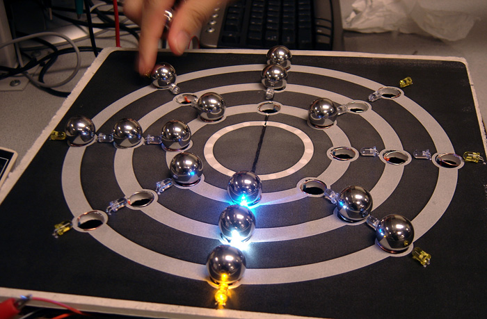
Fig. 12: Rhythm Ring in Action
V. Conclusion
Overall, we were very pleased with how well our hardware and software implemented the functionality of an interactive musical sequencer similar to that of Peter Bennett's BeatBearing.
Some aspects of our project were somewhat disappointing. The audio quality of our percussion sounds was not at the level we had hoped for. However, considering the time and resource constraints, lack of acoustics and signal processing experience, and the usage of a relatively low-quality single-supply DAC, we were satisfied with the final product that we submitted. If we had time to improve the audio quality, we would further investigate the Karplus-Strong algorithm and make another attempt at implementing a banded wave-guide model of percussion instruments.
In terms of intellectual property, we did not use any code from the public domain. We wrote our own code and built our own hardware from scratch. In a sense, we reverse-engineered the basic functionality Peter Bennett’s BeatBearing project, but we did so without any information other than what was shown in his demonstration video on YouTube. Nonetheless, we give Peter Bennett credit for the basic idea behind our project. Our design has some unique features, such as circular tracks, superbright LED feedback, control buttons for tempo adjustment, a circular "playhead" indicator which shows the current playback position, and full implementation and execution on an ATMega32 microprocessor. Our project does not require the use of a computer or any extra hardware, but it is consequently less flexible than the BeatBearing.
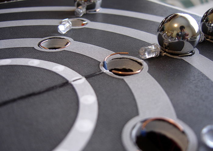
Fig. 13: Close-up of Ball Bearing Sensor and Superbright LED
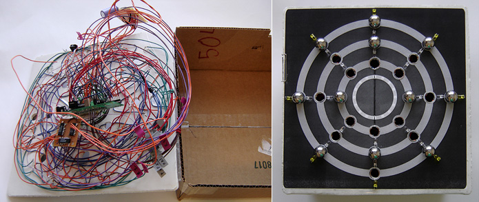
Fig. 14: The Final Enclosure (Open and Closed)
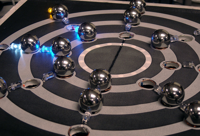
Fig. 15: Dimming LEDs During Playback
VI. Budget and Parts List
Our budget was restricted to $75, and we remained well below that limit at a total expense of $54.90. Obtaining many parts from the lab helped us keep our budget relatively low, and we further minimized costs by "shopping around" for parts that weren't readily available. For example, a typical good-quality DAC can cost more than $8. Using the lab-stocked National Semiconductor DAC0808 saved us a significant amount of money. We also chose to use foamcore board and salvaged cardboard for our enclosure platform rather than more expensive options like Plexiglas. We also salvaged most of the boards that we used for soldering ICs and other small components.
| Item |
Unit Cost |
Quantity |
Total Cost |
Source |
| Foamcore Board (30"x20") |
1.25/1 |
1 |
1.25 |
Cornell Store |
| Mux: 8:1 3-state 16-DIP |
0.50/1 |
3 |
1.50 |
Digi-Key |
| Mux: 16:1 Analog 28-SOIC |
5.72/1 |
1 |
5.72 |
Digi-Key |
| Steel Balls: 0.75" D |
11.48/25 |
25 |
11.48 |
McMaster-Carr |
| Superbright LED: 5mm Yellow 3000mcd |
0.20/1 |
8 |
1.60 |
MPJA |
| Superbright LED: 5mm Blue 3900mcd |
0.25/1 |
8 |
2.00 |
MPJA |
| Superbright LED: 5mm White 5000mcd |
0.20/1 |
8 |
1.60 |
MPJA |
| LED: 5mm Green |
1.95/100 |
16 |
0.31 |
MPJA |
| Atmel ATmega32 |
8.00/1 |
1 |
8.00 |
476 Lab Stock |
| Power Supply |
5.00/1 |
2 |
10.00 |
476 Lab Stock |
| ECE 476 Custom PCB |
5.00/1 |
1 |
5.00 |
476 Lab Stock |
| 8-bit DAC: National Semi DAC0808 |
1.74/1 |
1 |
1.74 |
476 Lab Stock |
| Header Sockets/Pins |
0.05/1 |
74 |
3.70 |
476 Lab Stock |
| Small Solder Board (2") |
1.00/1 |
1 |
1.00 |
476 Lab Stock |
| Component PCB (Various Sizes) |
Unknown |
2 |
0.00 (salvaged) |
Spare Parts Box |
| Cardboard Box |
Unknown |
1 |
0.00 (salvaged) |
Home |
| Blood, Sweat, and Tears |
Priceless |
5 weeks |
Undefined |
Brian & Hanson |
| Grand Total |
|
|
54.90 |
|
Table 2: Parts and Costs List
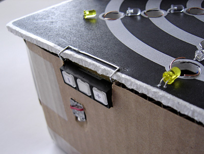
Fig. 16: Paperclip-derived Brace for Control Button Support
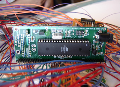
Fig. 17: ECE 476 Custom PCB with Atmel ATMega32 MCU
VII. Ethical and Legal Considerations
We closely abided by the IEEE Code of Ethics while designing and building our project. We hold these ethics in high regard because of the personal obligation that all engineers have to serve the community through the advancement of technologies.
Throughout the design phase, we ensured that we gave credit for ideas and techniques wherever it was appropriate. For example, we cited Peter Bennett and Charles Allen for their work and contribution in their respective fields. While in lab, we tried to share our discoveries and experiences (e.g. Charlieplexing and our attempts to implement the Karplus-Strong algorithm).
However, the most helpful and beneficial components of lab time (for everyone) were the constructive criticism and the sharing of projects and underlying technologies. During the last week before the project due date, many students shared about their projects with others as they worked side by side. Friendly exchanges were frequent as group members soldered components in the back of the lab room. This sharing of knowledge can inspire interest in what others have been working on, and could lead to more innovative and team-oriented project ideas in the future. To encourage this type of sharing, the class practiced fair treatment in the lab and did not allow racial, ethnic, or gender differences to take away from educational enjoyment while developing our projects.
VIII. Appendix
Schematics
Fig. 18: Full Schematic Overview [Full-resolution Schematic Here]
Fig. 19: Schematic Detail 1. Superbright Track LEDs
Fig. 20: Schematic Detail 2. Track Ball Bearing Sensors
Fig. 21: Schematic Detail 3. Audio Output, Playhead LEDs, and Tempo Control Buttons
ATMega32 Source Code
//-----------------------------------------------------------
// Brian Yung (bmy5) and Hanson Jiang (hcj4)
// ECE 476 Final Project - Spring 2008
// Rhythm Ring: Interactive Rhythm Sequencer
//-----------------------------------------------------------
#include <Mega32.h>
#include <stdio.h>
#include <stdlib.h>
#include <math.h>
// Audio sample tables generated with MATLAB (generatePercussionTable.m)
#include <snaretbl.h> // 4000 samples = 4 kB
#include <hihattbl.h> // 4000 samples = 4 kB
#include <basstbl.h> // 4000 samples = 4 kB
//-----------------------------------------------------------
// Definitions
//-----------------------------------------------------------
// Ball Table and Column Positions
unsigned char bearing_tbl[3][8];
unsigned char xpos, curxpos, nextxpos;
// LED Control Variables
long dutycycle;
unsigned char dutycycle_b0;
unsigned char led_period, led_dimming;
char dc1, dc3;
int dc2;
// Timing Variables
int tracktimer, beatperiod;
unsigned char time0;
// Button Input and Debouncing Variables
unsigned char butnum, lastbutnum;
// Audio Variables
int soundctr;
int audio_buffer;
char sound_playing;
// Variables for test_led() and show_off()
char a1, a2, a3;
char showtime, showrow;
char showrows[7] = {0, 1, 2, 1, 0, 1, 2};
unsigned char xpostemp;
// Initialization Variables
char r, c;
//-----------------------------------------------------------
// Function Prototypes
//-----------------------------------------------------------
void initialize(void);
void flash_led(void);
void test_led(int delay);
void set_led(char state, char r);
void show_off(void);
void scanbuttons(void);
void read_nextcol(void);
void update_playhead(void);
//-----------------------------------------------------------
// Main Routine
//-----------------------------------------------------------
void main(void)
{
initialize(); // run initialization routine
while(1)
{
// Update position
if (tracktimer == 0)
{
xpos++;
if (xpos == 32) xpos = 0; // loop around (base 32)
tracktimer = beatperiod>>2; // reset tracktimer to beatperiod/4
update_playhead(); // Update playhead LED
}
// Run single flash_led() cycle
if(led_dimming == 1) flash_led();
// Scan buttons
scanbuttons();
// At each of the 8 beats, check for bearings in next column
// Activate LED and audio if bearings exist in current column
if (xpos%4 == 0)
{
// Start playing sounds
soundctr = 0; // reset sound counter
sound_playing = 1;
// Sets flags & loop vars for flash_led()
led_dimming = 1;
dc1 = 0;
dc2 = 0;
dc3 = 0;
// Initialize duty cycle to full-on
dutycycle = 0xffff;
// Calculate current column number (0-7)
curxpos = xpos>>2;
nextxpos = curxpos + 1;
if(nextxpos == 8) nextxpos = 0; // loop around (base 8)
// Read bearings in next column
read_nextcol();
} //if
} //while
} //main()
//-----------------------------------------------------------
// Subroutines
//-----------------------------------------------------------
// Flash LED
//----------------------------
void flash_led(void)
{
// Dimming loop implemented with if statements for "rapid function call" execution
if(dc1<16)
{
// Output each complete duty cycle a certain number of times
if(dc2<led_period)
{
// Output each bit of dutycycle to appropriate LEDs
if(dc3<16)
{
dutycycle_b0 = (dutycycle>>dc3) & 0x01;
set_led(bearing_tbl[0][curxpos] & dutycycle_b0, 0);
set_led(bearing_tbl[1][curxpos] & dutycycle_b0, 1);
set_led(bearing_tbl[2][curxpos] & dutycycle_b0, 2);
// Inner loop condition (dutycycle reader)
dc3++;
}
// Middle loop condition (dutycycle repeat)
if(dc3 == 16)
{
dc2++;
dc3 = 0;
}
}
// Outer loop condition (dutycycle shifter)
if(dc2 == led_period)
{
dc1++;
dc2 = 0;
// Shift zero into dutycycle from left
dutycycle = dutycycle>>1;
}
} //if
// Reset led_dimming flag when done
if(dc1 == 15) led_dimming = 0;
} //flash_led()
// Test LEDs
//----------------------------
void test_led(int delay)
{
// Initialize duty cycle to full-on
dutycycle = 0xffff;
// Flash all LEDs and dim them
for(a1=0; a1<16; a1++)
{
for(a2=0; a2<delay; a2++)
{
for(a3=0; a3<16; a3++)
{
dutycycle_b0 = (dutycycle>>a3) & 0x01;
set_led(dutycycle_b0, 0);
set_led(dutycycle_b0, 1);
set_led(dutycycle_b0, 2);
}
curxpos++;
if(curxpos == 8) curxpos = 0;
}
dutycycle = dutycycle>>1;
} //for
} //test_led()
// Show Off LEDs
//----------------------------
void show_off(void)
{
xpostemp = xpos;
// Flash all LEDs and dim them
for(showtime=0; showtime<7; showtime++)
{
showrow = showrows[showtime];
// Initialize duty cycle to full-on
dutycycle = 0xffff;
for(a1=0; a1<16; a1++)
{
update_playhead();
xpos++;
if(xpos == 32) xpos = 0;
for(a2=0; a2<100; a2++)
{
for(a3=0; a3<16; a3++)
{
dutycycle_b0 = (dutycycle>>a3) & 0x01;
if(showrow == 0) set_led(dutycycle_b0, 0);
if(showrow == 1) set_led(dutycycle_b0, 1);
if(showrow == 2) set_led(dutycycle_b0, 2);
}
curxpos++;
if(curxpos == 8) curxpos = 0;
}
dutycycle = dutycycle>>1;
} //for
} //for
xpos = xpostemp;
} //test_led()
// Set Beat LED
//----------------------------
void set_led(char state, char r)
{
// Turn one individual bearing LED on or off
// r = row of LED to set (0-2), state: 1 = on, 0 = off
// Translate r into port/pin output state
switch(r)
{
case 0: // Track 1 (Inner)
if(state == 1) // Turn on LED at current column
{
switch(curxpos)
{
case 0:
DDRB.0 = 1;
DDRB.1 = 1;
DDRB.2 = 0;
DDRB.3 = 0;
PORTB.0 = 0;
PORTB.1 = 1;
PINB.2 = 0;
PINB.3 = 0;
break;
case 1:
DDRB.0 = 1;
DDRB.1 = 0;
DDRB.2 = 1;
DDRB.3 = 0;
PORTB.0 = 0;
PINB.1 = 0;
PORTB.2 = 1;
PINB.3 = 0;
break;
case 2:
DDRB.0 = 1;
DDRB.1 = 0;
DDRB.2 = 0;
DDRB.3 = 1;
PORTB.0 = 0;
PINB.1 = 0;
PINB.2 = 0;
PORTB.3 = 1;
break;
case 3:
DDRB.0 = 1;
DDRB.1 = 1;
DDRB.2 = 0;
DDRB.3 = 0;
PORTB.0 = 1;
PORTB.1 = 0;
PINB.2 = 0;
PINB.3 = 0;
break;
case 4:
DDRB.0 = 0;
DDRB.1 = 1;
DDRB.2 = 1;
DDRB.3 = 0;
PINB.0 = 0;
PORTB.1 = 0;
PORTB.2 = 1;
PINB.3 = 0;
break;
case 5:
DDRB.0 = 0;
DDRB.1 = 1;
DDRB.2 = 0;
DDRB.3 = 1;
PINB.0 = 0;
PORTB.1 = 0;
PINB.2 = 0;
PORTB.3 = 1;
break;
case 6:
DDRB.0 = 1;
DDRB.1 = 0;
DDRB.2 = 1;
DDRB.3 = 0;
PORTB.0 = 1;
PINB.1 = 0;
PORTB.2 = 0;
PINB.3 = 0;
break;
case 7:
DDRB.0 = 0;
DDRB.1 = 1;
DDRB.2 = 1;
DDRB.3 = 0;
PINB.0 = 0;
PORTB.1 = 1;
PORTB.2 = 0;
PINB.3 = 0;
break;
} //switch(curxpos)
} //if
else // Switch LED off via high-impedance
{
DDRB.0 = 0;
DDRB.1 = 0;
DDRB.2 = 0;
DDRB.3 = 0;
PINB.0 = 0;
PINB.1 = 0;
PINB.2 = 0;
PINB.3 = 0;
}
break;
case 1: // Track 2 (Middle)
if(state == 1) // Turn on LED at current column
{
switch(curxpos)
{
case 0:
DDRB.4 = 1;
DDRB.5 = 1;
DDRB.6 = 0;
DDRB.7 = 0;
PORTB.4 = 0;
PORTB.5 = 1;
PINB.6 = 0;
PINB.7 = 0;
break;
case 1:
DDRB.4 = 1;
DDRB.5 = 0;
DDRB.6 = 1;
DDRB.7 = 0;
PORTB.4 = 0;
PINB.5 = 0;
PORTB.6 = 1;
PINB.7 = 0;
break;
case 2:
DDRB.4 = 1;
DDRB.5 = 0;
DDRB.6 = 0;
DDRB.7 = 1;
PORTB.4 = 0;
PINB.5 = 0;
PINB.6 = 0;
PORTB.7 = 1;
break;
case 3:
DDRB.4 = 1;
DDRB.5 = 1;
DDRB.6 = 0;
DDRB.7 = 0;
PORTB.4 = 1;
PORTB.5 = 0;
PINB.6 = 0;
PINB.7 = 0;
break;
case 4:
DDRB.4 = 0;
DDRB.5 = 1;
DDRB.6 = 1;
DDRB.7 = 0;
PINB.4 = 0;
PORTB.5 = 0;
PORTB.6 = 1;
PINB.7 = 0;
break;
case 5:
DDRB.4 = 0;
DDRB.5 = 1;
DDRB.6 = 0;
DDRB.7 = 1;
PINB.4 = 0;
PORTB.5 = 0;
PINB.6 = 0;
PORTB.7 = 1;
break;
case 6:
DDRB.4 = 1;
DDRB.5 = 0;
DDRB.6 = 1;
DDRB.7 = 0;
PORTB.4 = 1;
PINB.5 = 0;
PORTB.6 = 0;
PINB.7 = 0;
break;
case 7:
DDRB.4 = 0;
DDRB.5 = 1;
DDRB.6 = 1;
DDRB.7 = 0;
PINB.4 = 0;
PORTB.5 = 1;
PORTB.6 = 0;
PINB.7 = 0;
break;
} //switch(curxpos)
} //if
else // Switch LED off via high-impedance
{
DDRB.4 = 0;
DDRB.5 = 0;
DDRB.6 = 0;
DDRB.7 = 0;
PINB.4 = 0;
PINB.5 = 0;
PINB.6 = 0;
PINB.7 = 0;
}
break;
case 2: // Track 3 (Outer)
if(state == 1) // Turn on LED at current column
{
switch(curxpos)
{
case 0:
DDRC.0 = 1;
DDRC.1 = 1;
DDRC.2 = 0;
DDRC.3 = 0;
PORTC.0 = 0;
PORTC.1 = 1;
PINC.2 = 0;
PINC.3 = 0;
break;
case 1:
DDRC.0 = 1;
DDRC.1 = 0;
DDRC.2 = 1;
DDRC.3 = 0;
PORTC.0 = 0;
PINC.1 = 0;
PORTC.2 = 1;
PINC.3 = 0;
break;
case 2:
DDRC.0 = 1;
DDRC.1 = 0;
DDRC.2 = 0;
DDRC.3 = 1;
PORTC.0 = 0;
PINC.1 = 0;
PINC.2 = 0;
PORTC.3 = 1;
break;
case 3:
DDRC.0 = 1;
DDRC.1 = 1;
DDRC.2 = 0;
DDRC.3 = 0;
PORTC.0 = 1;
PORTC.1 = 0;
PINC.2 = 0;
PINC.3 = 0;
break;
case 4:
DDRC.0 = 0;
DDRC.1 = 1;
DDRC.2 = 1;
DDRC.3 = 0;
PINC.0 = 0;
PORTC.1 = 0;
PORTC.2 = 1;
PINC.3 = 0;
break;
case 5:
DDRC.0 = 0;
DDRC.1 = 1;
DDRC.2 = 0;
DDRC.3 = 1;
PINC.0 = 0;
PORTC.1 = 0;
PINC.2 = 0;
PORTC.3 = 1;
break;
case 6:
DDRC.0 = 1;
DDRC.1 = 0;
DDRC.2 = 1;
DDRC.3 = 0;
PORTC.0 = 1;
PINC.1 = 0;
PORTC.2 = 0;
PINC.3 = 0;
break;
case 7:
DDRC.0 = 0;
DDRC.1 = 1;
DDRC.2 = 1;
DDRC.3 = 0;
PINC.0 = 0;
PORTC.1 = 1;
PORTC.2 = 0;
PINC.3 = 0;
break;
}
}
else // Switch LED off via high-impedance
{
DDRC.0 = 0;
DDRC.1 = 0;
DDRC.2 = 0;
DDRC.3 = 0;
PINC.0 = 0;
PINC.1 = 0;
PINC.2 = 0;
PINC.3 = 0;
}
break;
} //switch(r)
} //set_led()
// Button Scanning
//----------------------------
void scanbuttons(void)
{
// D.6 = Slower, D.7 = Faster
if(PIND.6 == 1 && PIND.7 == 0) butnum = 1;
else if(PIND.6 == 0 && PIND.7 == 1) butnum = 2;
else if(PIND.6 == 1 && PIND.7 == 1) butnum = 3;
else butnum = 0;
// Button D.6 cycles through available tempos
// Button D.7 switches between voices (drums and guitar)
if(butnum != lastbutnum) // Simple debouncing
{
if(butnum == 1) // Slower (Increase beat period up to 1000)
{
if (beatperiod < 1000)
{
test_led(30);
beatperiod += 100;
led_period += 5;
}
} // if
if(butnum == 2) // Faster (Decrease beat period down to 100)
{
if (beatperiod > 100)
{
test_led(30);
beatperiod -= 100;
led_period -= 5;
}
} // if
if(butnum == 3) show_off();
} //if
lastbutnum = butnum; // Save previous button for debounce
} //scanbuttons()
// Read Next Column
//----------------------------
void read_nextcol(void)
{
switch(nextxpos) // read next column
{
case 0:
PORTD.0 = 0;
PORTD.1 = 0;
PORTD.2 = 0;
break;
case 1:
PORTD.0 = 1;
PORTD.1 = 0;
PORTD.2 = 0;
break;
case 2:
PORTD.0 = 0;
PORTD.1 = 1;
PORTD.2 = 0;
break;
case 3:
PORTD.0 = 1;
PORTD.1 = 1;
PORTD.2 = 0;
break;
case 4:
PORTD.0 = 0;
PORTD.1 = 0;
PORTD.2 = 1;
break;
case 5:
PORTD.0 = 1;
PORTD.1 = 0;
PORTD.2 = 1;
break;
case 6:
PORTD.0 = 0;
PORTD.1 = 1;
PORTD.2 = 1;
break;
case 7:
PORTD.0 = 1;
PORTD.1 = 1;
PORTD.2 = 1;
break;
default:
PORTD.0 = 0;
PORTD.1 = 0;
PORTD.2 = 0;
break;
}
// Store state of ball sensor at next column for each track
bearing_tbl[0][nextxpos] = PIND.3;
bearing_tbl[1][nextxpos] = PIND.4;
bearing_tbl[2][nextxpos] = PIND.5;
} //read_nextcol()
// Update Playhead LED
//----------------------------
void update_playhead(void)
{
// Set 16:1 mux based on x-position every 1/2 beat
switch(xpos)
{
case 0:
PORTC.4 = 0;
PORTC.5 = 0;
PORTC.6 = 0;
PORTC.7 = 0;
break;
case 2:
PORTC.4 = 1;
PORTC.5 = 0;
PORTC.6 = 0;
PORTC.7 = 0;
break;
case 4:
PORTC.4 = 0;
PORTC.5 = 1;
PORTC.6 = 0;
PORTC.7 = 0;
break;
case 6:
PORTC.4 = 1;
PORTC.5 = 1;
PORTC.6 = 0;
PORTC.7 = 0;
break;
case 8:
PORTC.4 = 0;
PORTC.5 = 0;
PORTC.6 = 1;
PORTC.7 = 0;
break;
case 10:
PORTC.4 = 1;
PORTC.5 = 0;
PORTC.6 = 1;
PORTC.7 = 0;
break;
case 12:
PORTC.4 = 0;
PORTC.5 = 1;
PORTC.6 = 1;
PORTC.7 = 0;
break;
case 14:
PORTC.4 = 1;
PORTC.5 = 1;
PORTC.6 = 1;
PORTC.7 = 0;
break;
case 16:
PORTC.4 = 0;
PORTC.5 = 0;
PORTC.6 = 0;
PORTC.7 = 1;
break;
case 18:
PORTC.4 = 1;
PORTC.5 = 0;
PORTC.6 = 0;
PORTC.7 = 1;
break;
case 20:
PORTC.4 = 0;
PORTC.5 = 1;
PORTC.6 = 0;
PORTC.7 = 1;
break;
case 22:
PORTC.4 = 1;
PORTC.5 = 1;
PORTC.6 = 0;
PORTC.7 = 1;
break;
case 24:
PORTC.4 = 0;
PORTC.5 = 0;
PORTC.6 = 1;
PORTC.7 = 1;
break;
case 26:
PORTC.4 = 1;
PORTC.5 = 0;
PORTC.6 = 1;
PORTC.7 = 1;
break;
case 28:
PORTC.4 = 0;
PORTC.5 = 1;
PORTC.6 = 1;
PORTC.7 = 1;
break;
case 30:
PORTC.4 = 1;
PORTC.5 = 1;
PORTC.6 = 1;
PORTC.7 = 1;
break;
default:
// Do nothing for 1/4 beats
break;
} //switch
} //update_playhead()
//-----------------------------------------------------------
// Initialization
//-----------------------------------------------------------
void initialize(void)
{
// PORTA = Output for Audio
DDRA = 0xff;
PORTA = 0x00;
// PORTB.0-3 = Output for LED Track 1
// PORTB.4-7 = Output for LED Track 2
DDRB = 0xff;
PORTB = 0x00;
// PORTC.0-3 = Output for LED Track 3
// PORTC.4-7 = Output for Playhead LED Mux
DDRC = 0xff;
PORTC = 0x00;
// PORTD.0-2 = Output for Sensor Column Select Mux
// PIND.3-5 = Input for Sensor Row Read
// PIND.6-7 = Input for Control Buttons
DDRD = 0b00000111;
PIND = 0x00;
PORTD = 0x00;
// Timers
// Setup timer0 for 1 ms timebase
TIMSK = 0b10000010; //turn on [timer0 cmp match] and [timer2 cmp match] ISRs
OCR0 = 249; //set the compare reg to 250 time ticks
// Set prescaler to 64 and turn on clear-on-match
TCCR0 = 0b00001011;
time0 = 250;
// Setup timer2 for 45 us timebase (1/22.05kHz)
OCR2 = 90; //set the compare reg to 91 time ticks
// Set prescaler to 8 and turn on clear-on-match
TCCR2 = 0b00101010;
// Initialize positioning
xpos = 29;
curxpos = 29;
nextxpos = 0;
// Initialize LED variables
led_dimming = 0;
led_period = 15;
// Initialize sound variables
soundctr = 0;
audio_buffer = 0;
// Initialize tempo
beatperiod = 300; // default period = 750 ms
// Initialize tracktimer
tracktimer = beatperiod>>2; // initialize tracktimer to beatperiod/4
// Initialize button vars
butnum = 0;
lastbutnum = 0;
// Set up ball bearing state table
// Initialize all values to zero
for(r=0; r<3; r++)
{
for(c=0; c<8; c++) bearing_tbl[r][c] = 0;
}
// Enable interrupts
#asm ("sei");
// Test LEDs
test_led(150);
}
//-----------------------------------------------------------
// Interrupt Service Routines
//-----------------------------------------------------------
// Timer 0 compare ISR
interrupt [TIM0_COMP] void timer0_compare(void)
{
// Decrement the time if not already zero
if (time0>0) --time0;
if (tracktimer>0) --tracktimer;
// Reset 1 ms counter
if (time0 == 0) time0 = 250;
} //timer0_compare()
// Timer 2 compare ISR
// Output audio (if appropriate) at sampling rate of 22.050 kHz
interrupt [TIM2_COMP] void timer2_compare(void)
{
// Play audio if playback flag is high
if(sound_playing == 1)
{
// Clear audio buffer
audio_buffer = 0;
// Add bass if bearing present
if(bearing_tbl[0][curxpos] == 1) audio_buffer += bass[soundctr]>>2;
// Add snare if bearing present
if(bearing_tbl[1][curxpos] == 1) audio_buffer += snare[soundctr]>>2;
// Add hi-hat if bearing present
if(bearing_tbl[2][curxpos] == 1) audio_buffer += hihat[soundctr]>>2;
// Output current audio sample to DAC
PORTA = (char)audio_buffer;
// Check to see if reached end of sound samples (4000 samples per beat)
if(soundctr == 3999) sound_playing = 0; // End of samples, stop audio output
else soundctr++; // If end of samples not yet reached, increment counter
} //if
} //timer2_compare()
MATLAB Audio Waveforms and Source Code
Fig. 22: MATLAB-generated Audio Waveforms for Bass Drum, Snare Drum, and Hi-hat (from Left to Right)
% generatePercussionTable.m
% Brian Yung and Hanson Jiang
clear all;
% Generate snare drum values
for i=1:2600
snareslowdecay = (1-i/2600)
if(i<50)
snarefastdecay = 1-i/50;
else
snarefastdecay = 0;
end
lowdecay = (rand + sin(0.042*i) + sin(0.04*i))/2;
fastdecay = (sin(0.8976*i) + sin(0.837758*i))/2;
snare(i) = round(255*0.25*(snareslowdecay*lowdecay + 0.5*snarefastdecay*fastdecay) );
end
snare(2601:4000) = 0;
tsnare = transpose(snare);
sound(snare./255,22050);
% Generate hihat values
for i=1:1500
hihatlowdecay(i) = (1-i/1500);
if(i<70)
hihatfastdecay(i) = 1-i/70;
else
hihatfastdecay(i) = 0;
end
lowdecay = sin(2.5*i)*rand;
fastdecay = (sin(2.5*i) + 2*sin(0.2*i) + 2*sin(0.4*i))/3;
hihat(i) = round(255*0.5*(0.5*hihatlowdecay(i)*lowdecay + 0.25*hihatfastdecay(i)*fastdecay) );
end
hihat(1501:4000) = 0;
thihat = transpose(hihat);
sound(hihat./255,22050);
% Generate bass drum values
for i=1:4000
basslowdecay(i) = (1-i/4000);
if(i<20)
bassfastdecay(i) = 1-i/20;
else
bassfastdecay(i) = 0;
end
lowdecay = (sin(0.018*i) + sin(0.022*i))/2;
fastdecay = (sin(1.25664*i) + sin(5.5*i))/2;
bass(i) = round(255*0.5*(basslowdecay(i)*lowdecay + 0.6*bassfastdecay(i)*fastdecay) );
end
sound(bass./255,22050);
tbass = transpose(bass);
IX. Datasheets
- [PDF] MM74HC251N: 8-Channel 3-State Multiplexer
- [PDF] DAC0808: 8-bit Parallel-Input Digital to Analog Converter
- [PDF] DG406DY-ND: 16-Channel CMOS Analog Multiplexer
- [PDF] ATMega32: Microcontroller
X. Tasks
We split our work load fairly equally, which gave both of us a chance to work on nearly every aspect of the project. Consequently, several tasks listed below are shared.
Brian Yung
- Programming (focus on initial program structure and audio output)
- Audio synthesis research and modeling in MATLAB
- Soldering and assembly
- Testing and debugging
- Report writing and editing
- Schematic Design
Hanson Jiang
- Programming (focus on LED control, bearing sensors, and overall structure)
- LED control and Charlieplexing research
- Soldering and assembly
- Testing and debugging
- Report writing and editing
- Web report design
Fig. 23: Brian, Hanson, and a Chubby Bird from New York City (Left to Right, Please)
XI. References
- [Link] Peter Bennett's Project Site (Includes BeatBearing)
- [Link] Maxim-IC Application Note 1880: Charlieplexing - Reduced Pin-Count LED Display Multiplexing
- [Link] Instructables: How to drive a lot of LEDs from a few microcontroller pins. (Charlieplexing)
- [Link] Instructables: Minidot 2 - The holoclock (LED dimming via duty cycles)
- [Link] Stephen Dill, "Percussion Synthesis"
- [Link] ECE 476: Fixed Point DSP functions
in Codevision C and assembler
- Karplus, K., Strong, A. Digital Synthesis of Plucked-String and Drum Timbres. Computer Music Journal, Vol. 7, No. 2. 1983. p43-55.
- Cook, Perry R., Smith, Julius O. Theory of Banded Waveguides. Computer Music Journal, Vol. 28, No. 1. 2004. p37-50.
- [Link] All Electronics
- [Link] Digi-Key
- [Link] McMaster-Carr
- [Link] MPJA

|