
Introduction
The TriWheeler is a radio-controlled robot with three wheels. The lack of the fourth wheel is far from the only thing that renders it distinctively different from typical radio-controlled units. In addition to the capability of being freely controlled with a remote control, The TriWheeler has a smart autonomous mode that allows the unit to move freely without running into major obstacles. Furthermore, The TriWheeler features 3 speeds and the cruising speed could be easily adjusted using the remote control on the fly.
High Level Design
Inspiration | Logical Structure | Standards
Inspiration
The idea of our project stems from the concept of an autonomous vehicle. Having closely followed the 2007 DARPA Urban Challenge (Cornell has a participating team and did quite well), it is apparent that a future of driverless cars is soon upon us. With a deadline approaching in 5 weeks and a limited budget, certainly anything close to that extend is improbable and highly unrealistic. We decided to pursue a similar concept on a much, much smaller scale instead. A radio-controlled robot seemed reasonably doable and was eventually chosen.
In an attempt to make the project extra interesting, we took a rather unconventional approach and decided to build the radio-controlled robot with only three wheels--two front and one rear. The two front wheels would be each driven by a DC motor, whereas the rear wheel merely serves as a point of support to the frame of the robot. The autonomous component of The TriWheeler would come from the use of detection sensors and an accompanying algorithm that helps the unit avoid oncoming obstacles.
Logical Structure
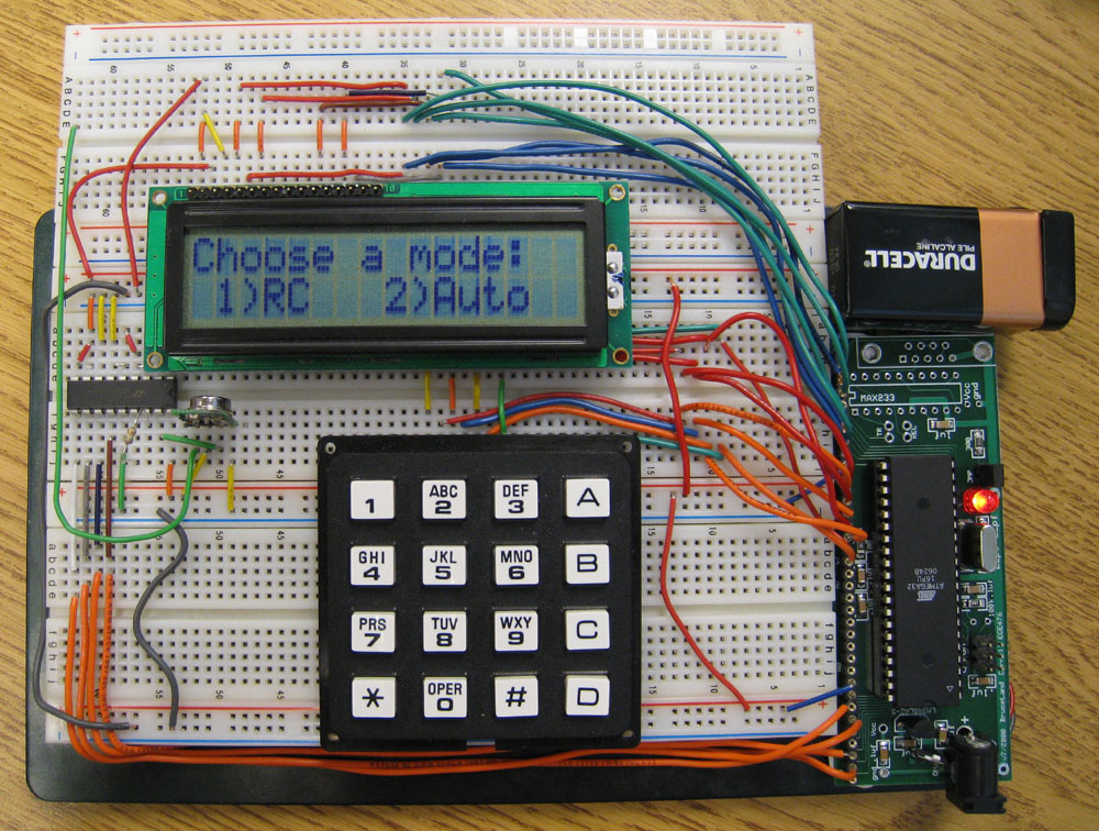
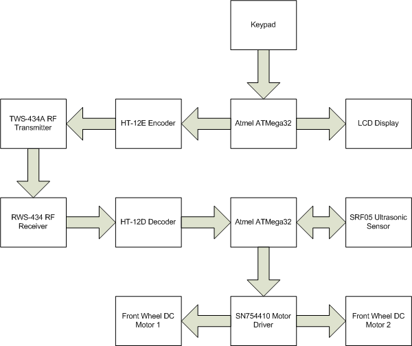
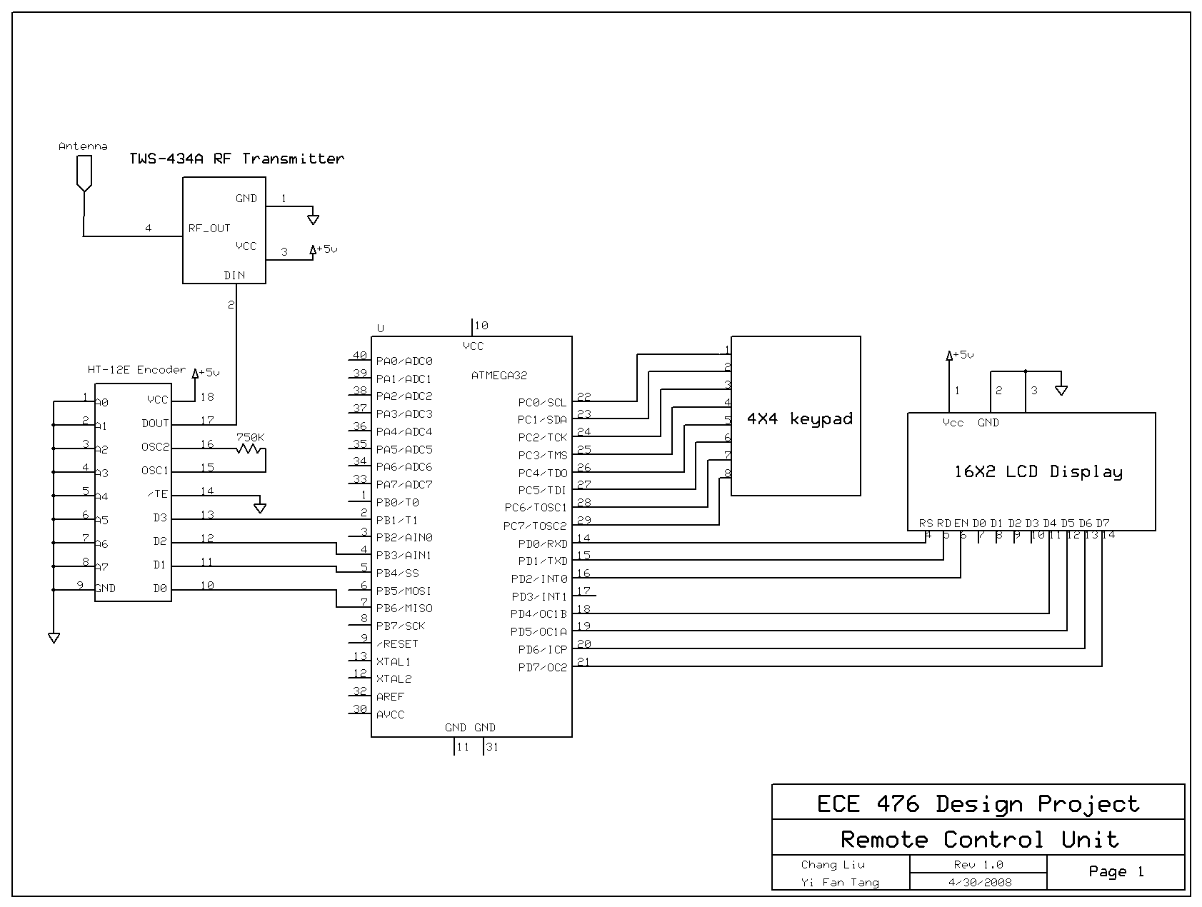
The project has two major parts: the remote control unit and the receiver unit. The keypad of the remote control unit serves as the single input device; it controls the movement of robot under manual mode and is also used to navigate the interface of the remote control displayed on the LCD. Commands from the keypad are processed by the ATMega32 microcontroller unit, encoded and then transmitted by the RF transmitter. On the receiving end, received commands are decoded, processed by the microcontroller and translated to a series of corresponding movements. Under the autonomous mode, sensors activate and detect continuously at timed intervals. At the same time, their outputs are monitored by the detection algorithm that is ran on the onboard microcontroller. The algorithm acts accordingly and ensures the robot stays clear of obstacles. The logical structure of The TriWheeler at a high level perspective is shown in the graph below.
Standards
The TWS-434A RF transmitter used in the unit complies with FCC standards and does not interfere with other licensed transmitters. It transmits within the acceptable range of frequencies specified in part 15 of the FCC.
Implementation
Hardware Design: Motor Control | Signal Transmission | Detection Mechanism
Software Design: Speed Control | Signal Handling | Detection Algorithm
Motor Control
Since we decided to build a robot with two front wheels each with its own DC motor, we were presented with a number of options to implement the steering system. Eventually we figured it is probably the best to run both motors simultaneously in opposite directions. This scheme provides us with an extremely responsive steering system. It later proved to be quite valuable as it complements certain shortfalls of our detection algorithm, especially when the TriWheeler is set to move at the high-speed mode.
Much of the motor control was accomplished through the use of the SN754410 Quadruple Half H-Bridge IC, essentially a single package that contains four h-bridge switches. The SN754410 package is particularly attractive to our project because not only it is cheap and readily available, the use of it dramatically reduces the amount of motor control circuitry that we need to build onboard the receiver unit. Furthermore, the use of h-bridges allows us to drive the DC motors conveniently in both clockwise and counterclockwise directions. Each half h-bridge contained in the package is capable of driving one DC motor in a single direction. In our implementation, two half h-bridges were used in conjunction with each other to provide bidirectional motion control.
Each half h-bridge contained in the SN754410 package has an nA input and an nY output. The nY outputs of a pair of half h-bridges are connected to the positive and negative inputs of the motor. The activation of either nY pins would trigger and start the motor. The direction of turning depends on the polarity of the motor pin that was connected to. This scheme allows the TriWheeler to move in forward and backward directions. To steer the TriWheeler sidewise, we manipulate the outputs of the half h-bridges such that one motor moves forward while the other moves backward. The output value of half h-bridges is controlled by the nA pin. The following table illustrates the four combinations of nA values as well as the resulting operations.
| Operation | 1A | 2A | 3A | 4A |
|---|---|---|---|---|
| Move Forward | 1 |
0 |
1 |
0 |
| Move Backward | 0 |
1 |
0 |
1 |
| Turn Left | 0 |
1 |
1 |
0 |
| Turn Right | 1 |
0 |
0 |
1 |
In addition to motion control, we also devised a multi-speed scheme using the SN754410. Notice from the pin layout, the SN754410 package contains two inputs, 1,2EN and 3,4EN. These two inputs are the enable bits for h-bridges 1, 2 and 3, 4, respectively. By varying the duty cycle of the PWM signal sent to these two enable inputs, the speed of the TriWheeler could be adjusted. This is equivalent to having the motor on only for a certain amount of time and on average, the speed is reduced. We set the period of the PWM signal to 0.64 s. From our experimentation, lower values seems to not as effective--probably due to the inertia associated moving motors. We implemented three different speeds for the TriWheeler and the speed could be conveniently adjusted from the remote control unit at any time.
Signal Transmission
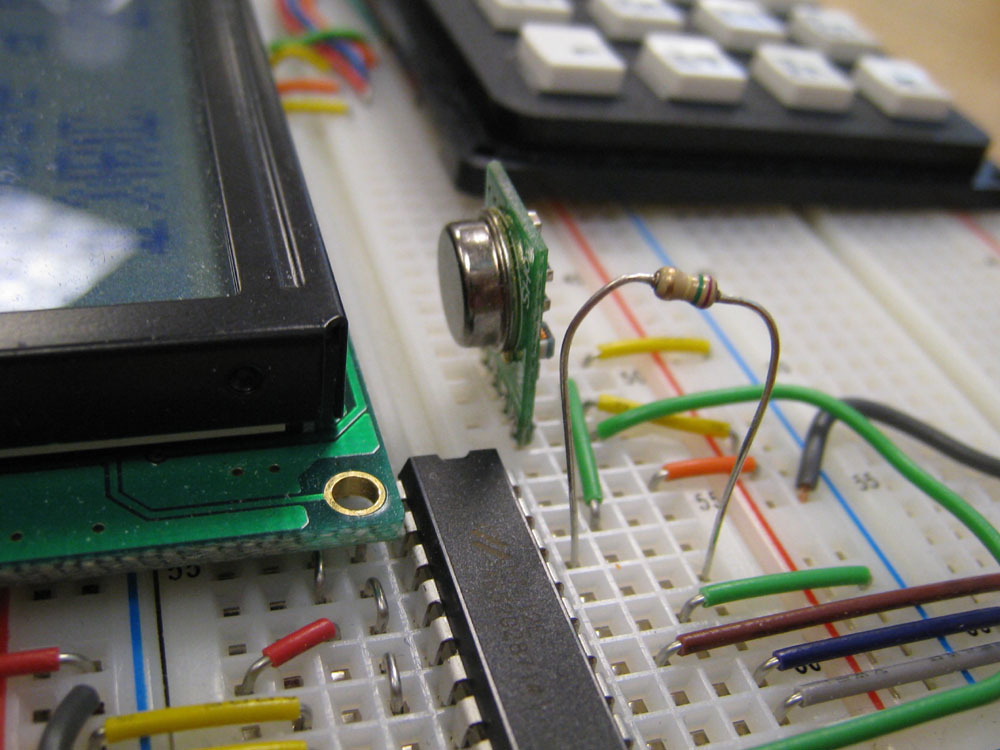
The signal transmission process from the remote control unit to the receiver unit is accomplished by using the HT-12E/H-12D encoder/decoder pair in conjunction with the TWS-434A/RWS-434 transmitter/receiver pair. Each control command is represented by a unique 4-bit message and after a command has been fetched from the keypad and processed by the ATMega32 microcontroller, it is immediately encoded by the HT-12E encoder. The encoded data are sent via the RF transmitter and a header bit is added for verification purpose. After receiving the data, the decoder proceeds to check for data integrity. The data are discarded if any error is detected and are otherwise decoded and then sent to the microcontroller onboard the receiver unit for further processing.
Detection Mechanism
The next major design decision was to choose the proper detection mechanism. Again, we considered a number of possibilities. Our initial plan was to use an infrared detector to estimate the distance to oncoming obstacles. After some further research however, we realized infrared was not robust and sufficiently versatile for our purpose. The consistent detection of distance is an essential prerequisite for automation and has a considerable amount of impact on the overall performance of the unit. Since infrared detectors depends highly on the surface material (due to potential absorption concerns), clearly this is not a very feasible option.
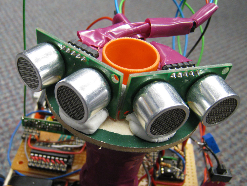
Our next candidate was ultrasound. Unlike infrared, ultrasound is unaffected by the different types of surface material we are likely to encounter. Ultrasound detectors are typically rather expensive. However fortunately, we were able to obtain a pair of SRF05 ultrasound sensor from a friend who possesses an extensive set of sensors.
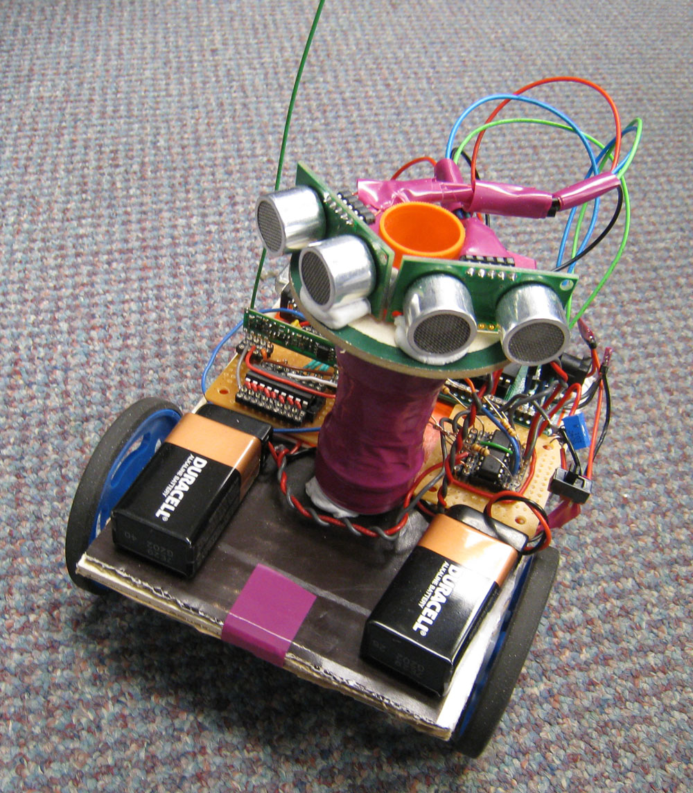
The pair of sensors were stabilized on a raised platform towards the front of the TriWheeler for optimized detection. The sensors are placed at an angle as shown in the picture. This particular arrangement is to accommodate our detection algorithm, which we will soon detail. The SRF05 sensor detects objects within range by sending out 8 consecutive cycles of ultrasound burst at 40 KHz. Immediately following this, the single output bit of SRF05 is raised to high while the sensor listens for feedback from these pulses. If an echo is detected, the output is set to low. The width of the output is therefore proportional to the distance to the detected object. Under autonomous mode, the SRF05 unit continuously performs this cycle and the output is processed by the ATMega32 microcontroller unit. Using the timer function, the microcontroller measures the width of the output in precise time unit. This value is equivalent to the actual distance from the object as the speed of sound is a constant.
Speed Control
Having described motor control on the hardware level, the speed control is a bit more straightforward. Speed control is achieved by sending PWM signals of varying duty cycles to the enable bits (1,2EN and 3,4EN) of SN754410 and therefore adjusting the rotation rate of motors to a desirable level. We used timer 1 and had ATMega32 set to Frequency Correct PWM, non-inverting Compare Output Mode with a prescaler of 256. In non-inverting Compare Output Mode, each time a match is detected between TCTN1 and OCR1A, the output compare (OC1A) is cleared if it is counting up and set if counting down. ICR1 is set to 20000 and a PWM with a frequency of 1.5625 Hz is produced. To produce the three speed levels, OCR1A was set to 3 different values. Theoretically, the actual speed should be linearly related to the OCR1A value. For instance, an OCR1A value that is half of ICR1 turns on both motors on average half the time and therefore, we expect to see the unit moving at precisely half of the top speed. However, this was not what we observed. The unit generally moved faster than we expected, probably due to the intrinsic inertia associated with the running motors. We calibrated the OCR1A values such that the three speed settings made sense and actual speed could be distinguished from each other without any ambiguity. The top speed has OCR1A set to 19900, the medium speed setting has an OCR1A value of 7500 and the lowest speed setting sets OCR1A to 2000.
Signal Handling
The remote control unit is set to send each command at a fixed frequency of 10 Hz, or in other words, every command is sent continuously for 100 ms. This design is to accommodate the signal transmission process such that it does not exceed the hardware processing capability. The microcontroller onboard the remote control unit times 100 ms by having Timer 0 set up in the Compare Match mode. On the receiver unit side, the decoder is wired to pins 6 and 7 of the microcontroller. The microcontroller of the receiver unit operates at a higher frequency than that of the remote control unit for a speedy response and it reads the decoder output every clock cycle.
Detection Algorithm
The detection algorithm is the heart of TriWheeler's autonomous mode. It is responsible for a number tasks. Upon the entering of autonomous mode, a 20 us pulse is generated using Timer 0 and sent to activate the ultrasound sensor pair. As previously described, the ultrasound sensor works by sending 8 consecutive cycles of ultrasound burst and listens for feedback echoes. During this listening period, no additional bursts should be sent or false detection may arise. Whenever an oncoming obstacle is detected, the output of the sensor is reset to low. Once activated, the sensor repeats this process and monitors continuously without intervention. The detection algorithm schedules the periodic listening of sensor outputs at 10 us time intervals. Two of such timers were set up to monitor each of the two ultrasound sensors. Each time an interrupt take place, the ultrasound sensor output is sampled. Thus to estimate the distance from the object, all we have then to do is to calculate the number of observed 10 us intervals by reading the values of the timer. The calculated distance values are then compared with the threshold distance value, which was set to 10 cm within the vicinity of the robot.
From the SRF05 ultrasound datasheet, we gathered that the distance can be estimated with: (the number of 10 us intervals observed) / 5.8. Through actual experimentation however, we found that a more precise formula turns out to be (the number of 10 us intervals observed) / 9. The difference is likely due to various delays in the process. The two sensors are positioned with a slight angle between them on a raised platform at the front of the TriWheeler such that one is responsible for detecting the front-left side and the other monitors the front-right side. Whenever an object is detected within the threshold distance (10 cm), the robot will immediately start turning and try to steer free of the obstacle. The actual direction of the turn is determined by first sensor that made the detection. If the left sensor first detects the oncoming object within the threshold distance, the robot will keep turning right until neither of the sensors could detect any object within the threshold distance.
With these conditions, the TriWheeler properly functions most of the time but could occasionally get stuck and end up continuously making rapid, alternating left and right turn adjustments. We noticed that this is particularly evident when the robot is approaching sharp corners; both sensors tend to make simultaneous detections and then attempt to correct the steering by sending conflicting correction turns. We addressed this problem by adding an additional routine to the algorithm. If at any time, both sensors made detections within a very short, preset threshold time, the sensor that made the first detection dominates the other and receives the priority of making turn adjustments. During the execution of these turn adjustments, both sensors are temporarily turned off and the robot attempts to complete a full U-turn. Upon the completion of which, both sensors are again reactivated. The addition of this routine to the detection algorithm resulted in a much more robust algorithm.
Results

Demonstration of TriWheeler's autonomous mode. Also available on Youtube.
While the TriWheeler generally met our initial expectations, it is not without flaws. Since each one of the two front wheels is driven by its own motor, on occasions (particularly evident when the motor battery is heavily drained) the TriWheeler tends to move in a slightly curved path. This problem was not quite expected as we were careful to choose identical motors and both motors were powered by the same 9-volt battery. Furthermore, our detection algorithm, though functioning, can still be improved. The algorithm we devised ensures that TriWheeler steers clear of obstacles by only making directional adjustments. We were considering making speed adjustments as well but were not able to make progress simply due to the time constraint. In addition, our current command set from the remote control unit is limited to a maximum size of 16 because the decoder/encoder pair used takes only four bits of data. Replacing the decoder/encoder pair would render additional commands available for us to use under the manual mode.
Conclusion
Concluding Remarks | Ethnical and Legal Considerations
Concluding Remarks
Overall, we were quite happy with the result. Though what we have achieved pales in comparison to the many near-autonomous vehicles at the 2007 DARPA Urban Challenge, we were very satisfied with what we managed to achieve in 5 weeks with limited resources. Of course, there are always places that could have been improved and new features to be added. We originally planned to use one ultrasound sensor and mount it on a flat, rotating platform driven by a servo motor and have the other sensor monitoring lower region straight ahead the robot. We were unable to pursue this design due to budget concerns as well as the fast-approaching deadline and had to eventually drop the idea entirely. Despite spending considerable time on choosing the proper detector, we were not able to settle until well into the 5-week period. This caused much unnecessary distress and could have been easily avoided. Again, proper time management is key to success.
Ethnical and Legal Considerations
The IEEE Code of Ethics was strictly observed and closely followed throughout the entire duration of the project. We made certain that the working environment was safe for us as well as our peers. While working in the lab, we treated other students with respect and shared lab equipments with courtesy. When handling heavy equipments, we made sure that minimal disturbance was caused. We designed and built our project with extra care such that there exist no foreseeable safety concerns. As far as we know, the TriWheeler would not cause harm or injury to any person or otherwise under normal operation. All components used in our project are compliant to current rules and regulations and there are no legal considerations.
Appendix
Source Code | Schematic | Budget | Tasks | Datasheets | Acknowledgements
Source Code
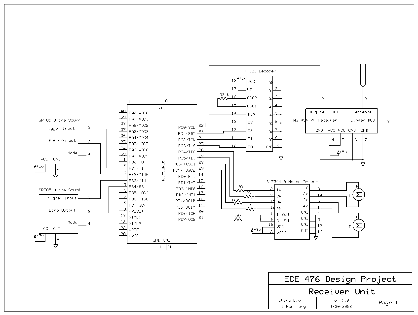
Schematic
Budget
The following table provides details of the parts used as well as the budget of the entire project. Our allowance for this semester is $75 and any exceeding amount adversely affects the final evaluation of the project.
| PART | QUANTITY | UNIT COST | TOTAL COST | SOURCE |
|---|---|---|---|---|
| ECE 476 Prototype Board | 2 |
$5.00 |
$10.00 |
ECE 476 Lab |
| 16 MHz Crystal Oscillator | 2 |
$0.00 |
$0.00 |
ECE 476 Lab |
| 9-Volt Battery | 3 |
$2.00 |
$6.00 |
Cornell Store |
| DIP Socket | 6 |
$0.50 |
$3.00 |
ECE 476 Lab |
| SIP/Header Socket | 182 |
$0.05 |
$9.10 |
ECE 476 Lab |
| Atmel ATMega32 | 2 |
$8.00 |
$16.00 |
ECE 476 Lab |
| LCD Display | 1 |
$8.00 |
$8.00 |
ECE 476 Lab |
| Keypad | 1 |
$6.00 |
$6.00 |
ECE 476 Lab |
| Switches | 2 |
$0.00 |
$0.00 |
ECE 476 Lab |
| Resistors, Capacitors | various |
$0.00 |
$0.00 |
ECE 476 Lab |
| Whiteboard | 1 |
-- |
-- |
Owned |
| Small Solder Board | 2 |
$1.00 |
$2.00 |
ECE 476 Lab |
| TWS-434A RF Transmitter | 1 |
-- |
-- |
Donated |
| RWS-434 RF Receiver | 1 |
-- |
-- |
Donated |
| HT-12D Decoder | 1 |
$1.90 |
$1.90 |
Rentron |
| HT-12E Encoder | 1 |
$1.90 |
$1.90 |
Rentron |
| SRF05 Ultrasonic Sensor | 2 |
-- |
-- |
Donated |
| SN754410 Motor Driver | 1 |
$1.65 |
$1.65 |
Rentron |
| DC motor | 2 |
-- |
-- |
Owned |
| Back Wheel | 1 |
-- |
-- |
Scrap |
| Front Wheel | 2 |
-- |
-- |
Owned |
| Cardboard | 1 |
-- |
-- |
Scrap |
| Total | $65.55 |
Tasks
The TriWheeler is the result of team effort. Both team members collaborated at all stages of the design project. Tommy was mostly responsible for software and Calvin spent more time on hardware and the project web page.
Datasheets
Acknowledgements
We would like to thank Bruce Land for providing various supplies at the lab. Thank you to our lab TA Sam Lee and Adrian Wong for the generous help and continuous support throughout the semester. Thank you to all of the TAs for keeping the lab open and generally available.