|
The goal of this project was to build a versatile, yet easy to use, sensor-triggered camera controller for high speed photography. |
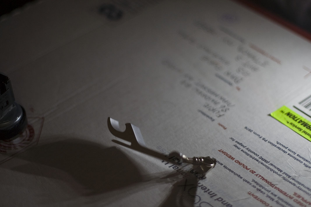
Photograph of a falling bottle opener taken with our system. |
High Level Design
Inspiration
Our motivation came from photographs that captured a very small moment in time, such as a water droplet splattering from a faucet or a balloon during the split second that it was bursting. Human reaction, and even a camera's shutter mechanisms, are too slow to reliably capture such precise moments in time. To overcome these limitations, we decided to employ a microcontroller hooked into various sensors and a high intensity LED array to control the shutter of the camera. Photographers interested in taking such pictures normally have to spend a lot of money on specialized equipment and lighting controllers, or they have to take hundreds of pictures and hope to get lucky. Our goal was to cheaply create a reliable system for high speed photography.
Concept
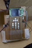
We decided to build our system using an interface similar to that of a cellular phone. An inexpensive color LCD, approximately 1"x1", coupled with a keypad taken from a Motorola RAZR provided a very convenient way to control the camera. A hierarchical menu system allows the user to set thresholds for sensors as well as other parameters of the shot, and then to initiate the shot by waiting for the triggers to fire. Various sensors were built to allow the user to take shots triggered acoustically, via an IR sensor, or even based on impact using an accelerometer. Finally, our homemade flash unit creates a quick and controllable light source to illuminate moving objects at just the right time.
Implementation Details
Hardware
The hardware for this system is comprised of the following
- Sensors
- Microphone
- Accelerometer
- Infrared ranging unit
- Camera shutter control circuit
- High powered LED flash unit
- 132x132 12-bit color LCD
- Keypad
Microphone
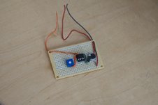
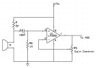
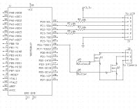
The microphone circuit consists of an electrolet microphone and an op-amp set up to be a non-inverting amplifier. The microphone is powered from the MCU board using the +5V rail. The microphone is fed through a 10uF electrolytic capacitor which serves as a decoupling capacitor. The signal is then put into the non-inverting input of the op-amp. The op-amp output is fed back through a potentiometer which serves as a variable gain for the circuit. The potentiometer output is fed back into the inverting input of the op-amp which provides the gain. The LM358 does not provide rail to rail voltages and is only able to provide a maximum of 3.7V output. However, we care very little about total output because we simply need to detect sounds such as snaps or claps. A user defined threshold for taking the picture is provided through the menu system on the LCD. Additionally, a meter on the LCD shows the peak value of the ADC input over 1 second intervals, allowing correction for ambient noise.
IR Sensor
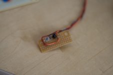
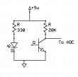
The IR sensor is a very simple device that works by reflecting infrared light off of an object and detecting the reflecting with a photo-transistor that is tuned to the same frequency of light. The LED is mounted next to the photo-transistor, however, the emitted light from the LED does not directly shine into the photo-transistor. Appropriate values for resistance are in series with both the LED to limit current and the photo-transistor in order to show a voltage drop based on distance to the object in front of the sensor. The effective range of the sensor is a few centimeters. Object detection can be enhanced by placing a reflective surface between the object and the sensor. When the object passes between the sensor and reflective surface, a large drop will be observed in the output signal.
Accelerometer
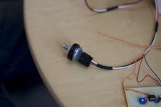
The accelerometer is very simple to use. The one being used is designed for automotive applications and is packaged in an extremely sturdy casing. This serves us well because we are using it to sense impacts of various types. The interface for the sensor is also very easy to use; the output signal is a voltage linearly related to the detected acceleration. Like the other sensors, an on-screen meter allows the user to set the threshold based on the detected peak values over 1 second intervals.
Flash Unit
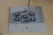
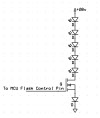
The flash unit consists of 5 3Watt LEDs in series with a BUZ73 power nmos transistor and a 1N4001 diode. The entire series is powered with a 20V power charger for an old laptop. This charger is an ideal power source because it provides a high current output along with a high voltage, all in a relatively compact form factor. Each LED drops about 3.7V, and the diode drops between .7 and 1V depending on the voltage. This helps to regulate the amount of current going through the LEDs. The LEDs are mounted on a piece of scrap aluminum with thermally conductive adhesive which prevents the LEDs from overheating.
LCD & Shutter Control
The shutter is controlled by a single npn mosfet. The camera is designed for remote shutter operation using a 2.5mm stereo mini-jack. When the middle pin is shorted with the first pin, the shutter is opened. The npn mosfet serves as a simple switch that shorts than pin when the gate is driven high by the MCU. The LCD is powered by an external 2xAA battery pack which provides the 3.3V needed by the sparkfun carrier board. Because the MCU drives its pin to 5V and the LCD takes a 3.3V signal input, a 1k resistor was placed in between the MCU and the LCD which drops the signal to an appropriate voltage for the LCD.
Software
The simplest implementation of this project could be realized with very little programming on top of what was done in labs. In essence the project consists of polling the A/D converter to detect thresholds being exceeded and then using a state machine to open the shutter, light the flash, and close the shutter. What made the software aspect of this project interesting and difficult was our menu system.
Our menu was organized hierarchically and had 10 different pages, some static and others animated. This was implemented as a giant state machine where transitions were triggered by button presses and the state changes caused the LCD to be updated. In addition to the menu state machine, we also used a keypad state machine adapted from the keypad library used in lab 2. The final state machine controlled the camera hardware by stepping through the process of taking a picture: opening the shutter, waiting for the sensor to be triggered, lighting the flash, and finally turning off the flash and closing the shutter. The menu and keypad state machines were based on 200ms and 30ms timers respectively, and the camera state machine was based off of a 10 microsecond timer to allow for finer control of the flash unit.
Menu State Machine
The menu state machine keeps track of many state variables including the current page and menu choice for navigation pages, as well as the selected input box for settings pages. Navigation pages can be controlled by up/down buttons to change menu choices, as well as select and back buttons to navigate to various pages of the menu. Some pages allow the user to choose settings for the camera such as the thresholds for sensors or the length of the flash. Thresholds are set by using the up and down buttons to move an indicator next to an analog meter which shows the current sensor signal. This allows the user to set a threshold appropriate for the ambient noise in the sensor's environment. Other inputs, for example the exposure time or the length of the flash, are set numerically using a 10 digit keypad. When camera settings are changed they can be saved to eeprom for persistence between uses. We also use the menu to begin a shot and then display an animated progress bar to let the user know the camera system in working.
The main loop checks to see if the menu needs to be updated every 200ms. If the user has pressed a button or if the page has animated content, then the menu needs to be updated by changing state and drawing the new menu to the LCD. Drawing functionality is extracted to a separate library in order to enhance code readability. Likewise camera control (getting and setting parameters, starting and stopping shots, etc.) is kept in a separate library.
Keypad State Machine
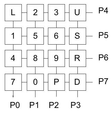
The keypad state machine runs at a higher frequency than the menu because the buttons need to be debounced quicker than the LCD needed to be updated. Using the keypad library from lab 2 as a reference, we designed a state machine to poll the 4x4 button matrix described above first horizontally and then vertically. If a button press was detected, a flag was set upon button release to indicate that the menu should be updated. A look-up table was used to translate 8-bit keypad readings into the corresponding buttons.
Drawing Functions
The details of drawing to the LCD were implemented using utilities adapted from the LCD library by Refik Hadzialic (see below for reference). Basic operations of this library include clearing the screen, drawing the various menu pages, and highlighting different choices on those pages. In some cases, especially the navigational pages, drawing was abstracted to allow various pages to be drawn using the same method. The settings pages were more unique and often required their own drawing methods.
The LCD library was based on code found at www.e-dsp.com. The code was used as a basis for getting the LCD working, however, much of it was changed in order to expand functionality and improve the speed and usability of the drawing functions. The init() function was changed to make it easier to follow, as well as enable 12-bit color versus the 8-bit color that was originally implemented. James Lynch's tutorial was also helpful in making these changes. Additional functions that were added include LCD_put_bitmap() which draws an image to the specified coordinates. Functions are provided to draw from arrays in both flash and RAM. A set_drawing_area() function was also created to reduce redundant code found in many of the functions. This command also helps to speed up drawing, because previously each pixel was drawn individually, even though the LCD controller allows for setting of a region to draw in, followed by a command to write information into that area by simply sending bytes sequentially. Draw box uses the set_drawing_area function to color regions. To convert the code from the 8 bit color to 12 bit color, special consideration had to be made going from only having to send 1 byte for a pixel to 2 bytes for a pixel. Each pixel is represented by 3 sets of 4 bytes, one for red, green, and blue. Colors represented as integer values have to be parsed into the proper format for sending to the LCD. The last modification that was made was implementing a set of functions for drawing characters to the screen.
Camera Control
We attempted to separate the actual control parameters and camera functions from the graphical interface by storing and updating the camera variables through a separate library. All thresholds and other settings were kept in eeprom and the menu system accessed them only through getter and setter methods in the camera library. The camera library also directly controlled the camera state machine through the checkShot() method. Separating these functions from the main menu loop helped to keep code clean and readable.
Main Control Loop
The program begins in menu.c by initializing state variables for the various state machines as well as MCU control registers. Timer 0 was set to use a clock prescalar of 64 and trigger a compare on match interrupt every 250 ticks, thereby resulting in a 1ms timer. This was used to clock the keypad and menu state machines. Timer 2 also used a prescalar of 64 but interrupted ever 25 ticks to create a 100 microsecond clock for more precise timing in the camera loop. The ADC was configured to use AVCC (5V) for calculations, and a prescalar of 128 on the XTAL frequency.
The main while loop checks and resets the timers. When the LCD is checked every 200ms it is updated if a button has been pressed (as indicated by the refreshLCD flag) or if the menu is on a dynamic page (as indicated by the onDynamicPage() method). Then the camera state machine is checked every iteration to provide the finest grain control. Finally the maximum ADC values are checked so that the analog meter on the threshold settings pages can be updated.
Results
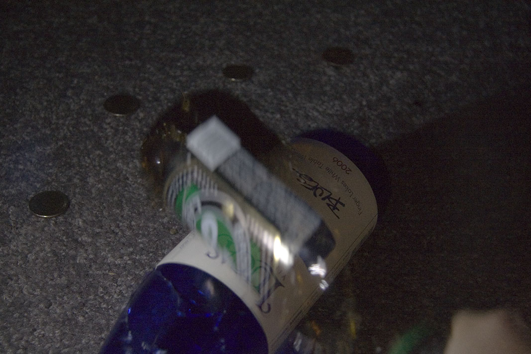
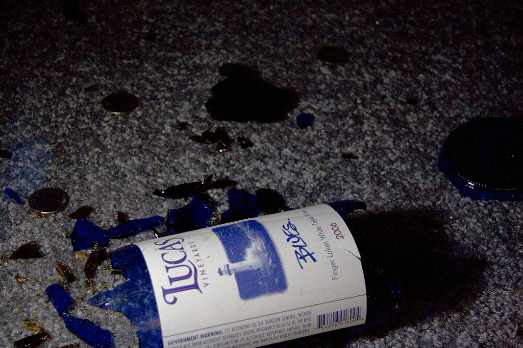
Using the system we made, we were able to capture very fleeting moments in time. From testing with the oscilloscope, we measured that there is only a few hundreds of microseconds between the triggering event and the start of the flash. This is a great improvement over what the camera alone can do, which at best is 100ms, but was shown to be as high as 200ms. For capturing the types of images we wanted to take a 100ms delay before opening the shutter is completely unusable. The flash unit cuts the delay down to fractions of a millisecond which allows us to capture the precise moment that a wine bottle breaks.
Our design lacks the needed flash power to take really fast pictures. To get enough light output to take a decently exposed photo we had to run the flash for about 1ms or more. A dedicated flash unit for an SLR camera is able to output many times more light in under 1/15000th of a second. However, a midrange consumer-grade flash unit costs about $250; ours was put together for less than $25.
Safety for this project is left to the user. It is never a good idea to look directly into any bright lights for any amount of time. However, considering the light output of our flash unit versus a normal xeon flash lamp found on most modern cameras, we feel that it would be extremely hard to do any permanent damage to ones eyes; the duration and intensity of the light just is not great enough to cause anything more than seeing a few spots.
|
|
Before and after of two bottles breaking and triggering the microphone sensor. Note the cracks forming in the wine bottle in the before picture
Conclusion
We were very happy with how our project turned out: we felt like we met almost all of our expectations. We were not able to produce professional quality photos, but this was expected since we saved hundreds of dollars compared to what the professional systems cost. We were able to control our camera with the microcontroller and take high speed shots in response to audio, accelerometer, and light triggers, and our makeshift flash unit provided the immediate illumination we needed.. The graphical menu was very intuitive and easy to use, and the device could be powered by a battery for portable use.
There are a few things we would change if we were to do this again. We did not have time to put the project in a case and ideally we would have preferred it to be more asthetic. Some convenient additions would be connectors for the CAT5 cables which connect the sensors to the MCU. It would also have been nice to get the keypad from the Motorola RAZR to work reliably, but in the practice we usually just press the buttons directly since that always works. We also did not implement the "number of shots" functionality since we found its uses to be rather rare. It could be helpful for extended exposure shots where you might want to take photos at a regular interval, but for the high-speed shots it is not possible to open and close the shutter fast enough to capture multiple shots.
We are sure this product will prove itself to be useful in the future, especially as a tool for photography enthusiasts. We hope others who are interested in this hobby will find our project useful and we would be happy to answer any questions regarding the system via the email addresses listed above.
Ethical and Legal Considerations
Our project avoids many of the ethical issues that were discussed in class this semester due to its nature as a recreational tool. Though it is unlikely that our project will be tested by tough moral and ethical questions, that is not to say that during the development process we did not have to make ethical choices. We made sure to cite the authors whose code we borrowed and whose example we followed. One circumstance that was probably unique to our group is that Dan had experimented with the STK500s prior to taking this course and had actually toyed with the idea of building a photography system. Though he never actually built the system, he did purchase some of the parts during his junior year and wrote some code to experiment with them. This raised an ethical question for us since we were afraid that his previous experience would preclude us from choosing this project, but we believe we made the correct decision by approaching the professor early in the semester and explaining the situation rather than hiding the facts. Luckily we were told to go ahead with the project and we have not had to worry about whether or not we were ethical in our choice of project.
From a legal perspective, we used the code we borrowed within the limitations of the stated agreements and cited whenever possible. We do not believe our project is patented nor do we plan to pursue any patents on it. We did not use any standardized technologies in our project.
Appendices
Circuit Diagrams | Budget | References | Tasks | Code Listing
Diagrams
Budget
| Part | Cost |
|---|---|
-- |
$46.75 |
| Custom PC Board | $5 |
| 2x Small Solder Board | $4 |
| Large Solder Board | $2.50 |
| Power Supply | $5 |
| ATMEGA32 | $8 |
| 20x Header Pin | $1 |
| 2x DIP Socket | $1 |
| 5x Luxeon 3Watt LED | $20.25 |
| Electrolet Microphone | Previously had |
| 2.5mm Stereo cable & jack | Previously had |
| LM358 | From lab |
| IR LED | From lab |
| IR Photo-transistor | From lab |
| BUZ73 | From lab |
| 1n4001 Diode | From lab |
| Resistors & Capacitors | From lab |
| Sensata Automotive 10g single-axis accelerometer | Surplus from FSAE car lab |
| LCD & carrier board | Previously had |
| 19.5V Power Supply | Leftover from an old broken laptop |
| Scrap aluminum | Scrap from the FSAE lab |
| Push buttons | Previously had |
References
- Epson LCD Controller
- Display information
- Philips LCD Datasheet
- LCD Product Page/Useful information
- LCD sample code
- Luxeon III Datasheet
Tasks
- Scott
- Menu system
- Drawing library
- Input system
- Keypad
- Dan
- Microphone circuit
- IR Sensor
- LCD interface software
- LED flash unit
- misc. hardware
Code Listing
The code for this project can be downloaded here. This code is licensed under the GNU General Public License.
©2008 Dan Furie and Scott Linderman

