
Radio Frequency Beacon Finder
This project is a radio frequency receiver that will help the user the trace the direction and distance of transmitter beacon(s) operating at 433MHz frequency.
In this ECE 476 final project, we have built a radio frequency receiver unit with an LCD screen that will display information about the RF signals that it is picking up in the vicinity: beacon ID, packet loss from a particular beacon, and the overall signal strength within the vicinity. All of which are useful information to help guide the user to the location of the beacons. The user will be able to determine the direction of the beacons by comparing the signal strength as he or she sweeps the directional Yagi beam antenna.
Eric Yu (eky2)
Eric Chin-Hung Chen (cc459)
High Level Design
Inspiration |Background| Logical Structure | Tradeoffs | Standards
Project idea inspiration
We got our inspirations for this project idea from one of the group members – Eric Yu – who has the extremely sloppy habit of leaving and losing his personal belongings on a regular basis. We thought that it would be a very good idea if there is a device that will be able to display the whereabouts of small attachable radio frequency tags or beacons on his personal belongings. Ideally, the device will be able to track multiple beacons, and display direction and distance of each beacon relative to current position of the receiver. As we will find out later, there are many functions which we will have to trade-off due to fundamental hardware and theoretical limitations.
Background
An antenna is a piece of wire that carries an alternating current. The alternating current generates an electromagnetic field which varies along with the current. Another wire of similar length at a distance away may be induced by this electromagnetic field and a copy of the current would run in the wire, but weaker. This is the theory of radio frequency communication.
There are many different ways of making antennas, and antennas of different shapes respond differently to radio signals – namely, their radiation pattern is different. The simplest of all antennas, the whip antenna, is just a piece of wire of a particular length. This length is specific to the frequency of that the radio wave operating in:
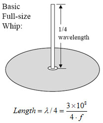
Where f is the frequency
(Source: Antennas for Low Power Applications, Kent Smith, RFM Corp.)
The whip antenna has a radiation pattern like the following:
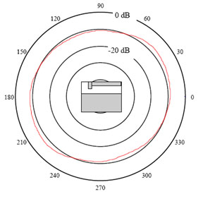
(Source: Antennas for Low Power Applications, Kent Smith, RFM Corp.)
From the radiation pattern, we can see that the whip antenna has almost equal gain in all directions. This means that it responds equally well to radio waves from all directions.
Another antenna design that is of particular interest to our project is the Yagi-Uda directional beam antenna. A directional beam antenna means that it has particularly high gain in response to radio waves from a particular direction, much like the following radiation pattern:
(Source: RFCafe)
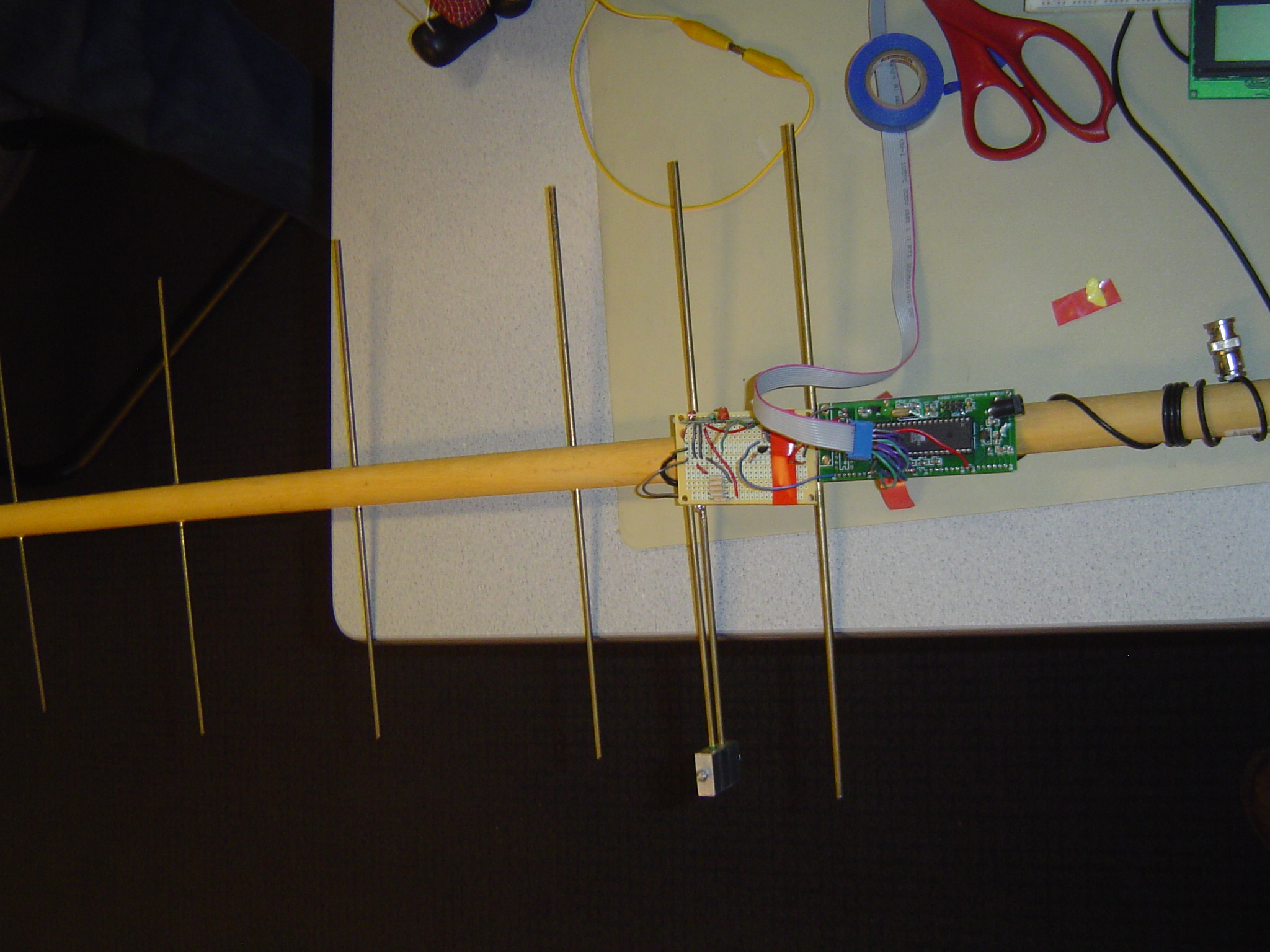
A Yagi-Uda antenna has three type of antenna elements: reflector element, driven element, and the direct elements. The driven element is the one that is connected to the receiver module. The reflector element is the lone one that is the most distant from the driven element, and director elements are on the other side of the driven element, each shorter and closer to the element preceding it. Here is an image of the 6-element Yagi that we will be using for this project:
(Source: Sky Scan Science Awareness Project)
There are many more parameters to designing a Yagi-Uda antenna, such as rod diameter, number of driven elements, etc. Free applications are available on the web to calculate the dimensions of a Yagi antenna, such as the Quickyagi modeling
software from WA7RAI. However, a quick formula is available:
Reflector length: 0.495 * wavelength
Driven length: 0.473 * wavelength
Director 1: 0.440 * wavelength
Director 2: 0.435 * wavelength
Director 3: 0.430 * wavelength
Director 4: 0.423 * wavelength
While the spacing can be calculated by this:
Reflector to Driven: 0.125 * wavelength
Driven to Director 1: 0.125 * wavelength
Director 1 to Director 2: 0.250 * wavelength
Director 2 to Director 3: 0.250 * wavelength
Director 3 to Director 4: 0.250 * wavelength
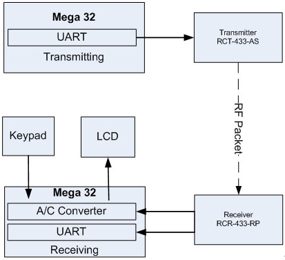
Logical Structure
Hardware and Software Trade-offs
During the course of our project, there were many design considerations and especially hardware-software tradeoffs that affected the type of technology we used. Our project proposal underwent several evolutions as a result of trying to meet these limitations.
Initially, we wanted to incorporate commercially available RFID tags for our beacons. For the purpose of increased distance up to several hundred feet, these tags would be active RFID tags. Active RFID tags are different from conventional passive RFID tags because they actually contain a built-in power source to help amplify their signal across long distances. This would have the advantage in that we would not have to develop the RF tags. Commercially available tags are also extremely small to begin with and would fir our initial idea of attachable tags on personal items better.
Unfortunately, this was not implemented because we realized the difficulty in decoding and accessing these tags. The tags themselves are not encoded to a standard that is readily accessible and attempts in doing so may turn out to be time consuming and not worth the effort. Secondly, active RFID tags are extremely expensive and can cost up to $20 per tag. When taking our purposes into consideration – tracking down RF beacons – we decided that a simple RF transmitter using the Radiotronix RCT-433 module would be a better fit for our project. These transmitters also could not be as small as the TFID tags. In the end, we had to sacrifice having readily available and miniature RFID tags for ease of development and lower costs.
The second trade-off we encountered was in designing our software. This trade-off fundamentally changed our project and redefined what we could achieve with existing technology on hand. One of the main draws of our initial project proposal was that we would be able to estimate the distance and direction of the RF beacons through calculation involving time-of-flight. Our initially plan involved two RF receivers placed at each end of the receiver module. By measuring the time it took the signal to travel from the beacon to each of the receiver antenna, we could extract information on how far away the beacon is. Furthermore, we could also theoretically derive the relative direction of the beacon by comparing the time-of-travel (thus the distance) at the two receiver antennas and using triangulation. Ideally, these could have all been easily implemented, but we came to the realization that at such small distances, the time of flight would be at the scale of nano-seconds and very easily influenced by error and noise. It is not a degree of accuracy that can be processed by the cheap ATMEGA-32. This is even more true for estimating the direction because the difference in the time-of-flight between the two antennas would be miniscule and almost impossible to calculate accurately for our system.
We would choose to implement the time-of-flight with triangulation idea next time if better hardware were available to us. But at the present stage, we have to settle for analyzing relative signal strength of all RF signals operating at 433MHz within a proximity to the RF receiver station. This would at least give us and the user an idea about where the beacon is by heading towards the direction of greater signal strength according to the receiver. To help achieve this, we have selected the Yagi-Uda directional beam antenna design as indicated in previous sections.
Technology Standards
The technology standard we have to consider in our project is the FCC standards and regulations regarding wireless and radio frequency devices. We have to read the FCC regulations carefully to make sure that our project does not violate federal laws regarding this matter.
Software and Hardware Implementation
Software Design
Radio Frequency Transmissions
For the transmission and receiving of the radio frequency packets, we used Meghan Desai’s “Wireless Rx/Tx Protocol,” which is available here. During transmission, we do not care so much for the actual content of transmission because we are more interested in how efficient the content is transmitted as a measure of signal strength. The transmission side would assume a pre-set transmitter ID (Default: 9) and send packets of length 1 at regular intervals. The packet content is simple counting up numerically from 1 to 255: the range of a char variable.
Measurements
Simple polling was activated on the receiver side’s micro-controller chip for the analog-to-digital conversion operations. The ADMUX was set to 01100000 to activate the A/D converter and use the internal 5V as its reference voltage. At the input Pin A.0 is the raw analog output from the RCR-433 receiver module. However, the signal strength would not be able to distinguish between signals coming from our own beacon and signals from other systems operating at the same frequency. The converted value of the analog antenna signal is displayed onto the LCD display.
The software also tracks the rate of packet loss from a specific RF beacon. This is achieved by comparing the counting-up value in the data payload of each packet transmitted. By comparing a packet’s number and the number of the previous packet received, we can determine how many packets were lost in the process between this transmission and the one before it. Our device is programmed to ignore any packets with length longer than 1, thus filtering out a good fraction of outside interference. This is based on the principle that packets of length 1 are quite useless for other applications so only beacons belonging to our system would have such packet length.
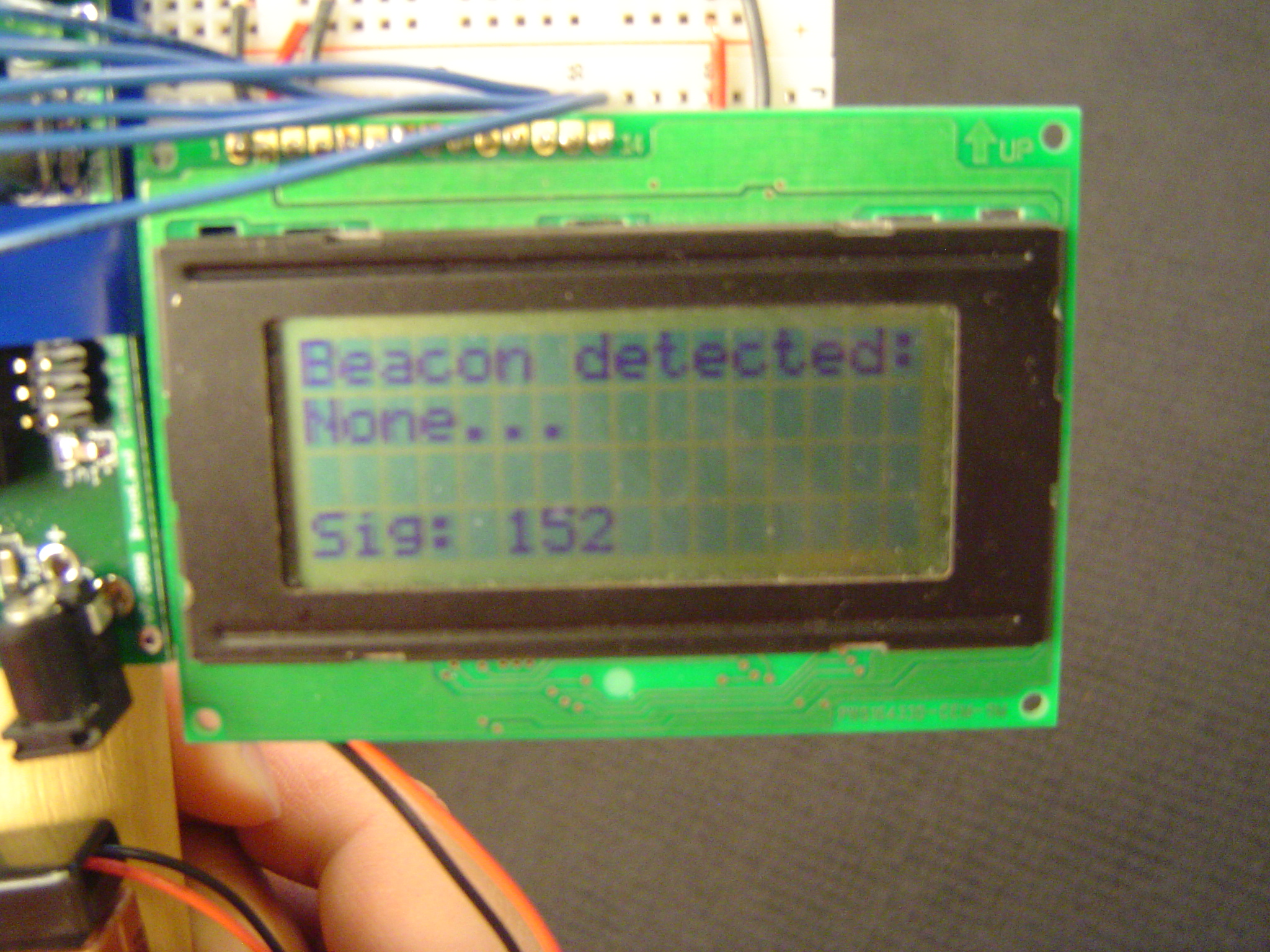
User Interface
A simple user interface involving a 16x4 LCD display will display useful information regarding signals it is receiving. It will always display “Beacon detected:” When the microcontroller determines that it has not detected any beacon it is responsible for (outside interference in the same frequency is ignored), it will display “Not found” If a beacon it is responsible for is in close vicinity and successfully transmits one packet free of data corruption, it will display the ID of that beacon. In line three, it will display information regarding packet loss.
The user can use the hexadecimal keypad and press A at any time to modify the beacon that the device is tracking. Valid beacon IDs are from 0 to 9.
“Not tracked ID” is displayed if the device detects a great signal presence (above 190) to warrant the existence of a signal nearby, but the decoded ID does not fit the beacon that is being tracked. Another case when “Not tracked ID” is displayed is when the device fails to decode the ID regardless of which ID it is.
Once the signal strength falls beneath a set level of 160, the microcontroller will determine the beacon has left the proximity or has been turned off, and the display will revert back to “None…”
Hardware Design
Antenna
Using the whip antenna equation mentioned previously in the high level design section, we can calculate that our whip antenna should be around 18.3 cm long. We cut out a length of wire that is this long and attached it to our receiver module.
For the Yagi antenna, following the formula mentioned in the previous section will give us the following dimensions for a 6-element antenna:
Lengths:
Reflector = 34.29cm
Driven = 32.7 cm
Director 1 = 30.5cm
Director 2 = 30.16cm
Director 3 = 29.85cm
Director 4 = 29.3cm
Separation:
Reflector to Driven = 8.6cm
Driven to Director 1 = 8.6cm
Director 1 to Director 2 = 17.1cm
Director 2 to Director 3 = 17.1cm
Director 3 to Director 4 = 17.1cm
Fortunately, Dr. Bruce Land already has a Yagi antenna which fits the above description that is he is willing to lend to our group (for this project only) at no cost. The antenna is to be returned to him at the end of the project.
Transmitter
![]()
The transmitter beacon uses the Radiotronix RCT-433 RF transmitter module and transmits data at 433MHz. The circuit design is almost entirely derived from Tytus Mak and Daniel DiBernardo’s design project from Spring 2007 Touch Screen Controlled R/C Car, which in turn is also borrowed from Donn Kim and Antonio Dorset’s Dual Control R/C Car. We made one change to the circuit because there is no 47uH inductor element. One way to do it would have been to custom-make an inductor using wound wire. Because inductance add up in series much like resistance, we found that wiring five 10uH inductors in series will give us 50uH.
Although 50uH is 3uH greater than what is specified on the circuit diagram, the results were acceptable and used this inductor design for both our transmitter and receiver.
Receiver
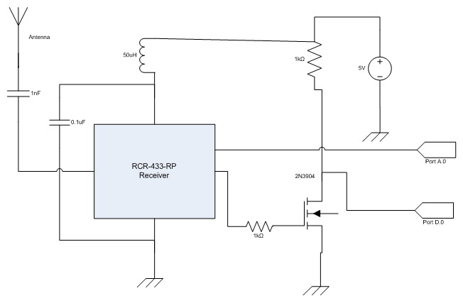
Here is the design we used for our receiver, which, like our transmitter, is also taken from Tytus Mak and Daniel DiBernardo’s project from last year. The receiver uses the RCR-433 receiver module, also available from Radiotronix. However, we made one change to the receiver design in that we also used the pin 6 output: raw analog signal from the RF receiver and connected it to Pin A.0 of the microcontroller (the A/D converter input).
User interface hardware
Our project also includes a 16-button hexpad for user-input purposes, and a 16 x 4 LCD display. Both of these were used in class labs throughout the semester. The hexpad and the LCD display are directly connected the microcontroller as indicated by the logic structure in High Level Design.
Things that did not work
We were able to avoid problems in the actual design of the system because we have pre-determined and weighed beforehand what is and what is not achievable with the equipment we have available. This is all described in the software-hardware tradeoffs section.
However, as we have said, tracking by signal strength has some fundamental flaw in that if there are multiple signal sources operating at 433MHz, it is impossible to tell which source is at which signal strength. This means that tracking by signal strength only works if there is one beacon in the vicinity, or there are no other interferences operating at the same 433MHz frequency.
Also, we had difficulty converting the raw data output of the Analog/Digital converter. Ideally for radio frequency signal strength, the units to use would have been dbmW, db, or just W for watts. This is something we could look into in the future.
Results
The device operates to a reasonable speed. The LCD display for signal strength updates every second. There is really not that much of a speed metric when determining the performance of this device. Unfortunately, this device performs sub-par in the accuracy category.
This device is very accurate when there is no beacon in the vicinity. Signal strength needs to rise above 170 for the device to determine that a beacon is in the vicinity. However, this device has great difficult identifying the signal it is detecting. Apparently the device might have trouble capturing complete signals for the receiver to decode it into acceptable data for the microcontroller. If the signal integrity is poor, then no matter how close we place the antenna, it sometimes would have difficulty identifying the beacon. It will recognize that there is signal, but it will not be able to recognize the beacon if the packets cannot be interpreted. Overall, I find that our device accuracy is fairly low when detecting beacons. But the signal strength reading is adequate to a degree as long as no other devices are operating in 433MHz at the same time.
This device is safe. There is no danger of a user being electrocuted due to the 9V battery power. However, the antenna is a small hazard because of its aluminum rod elements. Care must be taken when wielding the antenna to make sure that no one gets jabbed by it.
The receiver does not interfere with operations of other projects or devices at 433MHz. However, the transmitter does and care must be taken to make sure that we do not disrupt the operation of other devices.
The transmitter is unaffected by outside interference in the radio frequency range, but the receiver will be somewhat affected. Although it will not detect a foreign signal or beacon due to the conditions we have set in our program that restricts it to only signals of length 1. However, the signal strength reading will be greatly affected by other devices operating in 433MHz.
Using this device turns out to be fairly tricky. It appears to catch readings of beacons better if it is tilted vertically, and some skill is required to position the antenna so that the beacon ID can be read. Otherwise, no skill is required to use the signal strength reader at all.
Conclusion
In conclusion for our final project, we have designed a radio frequency antenna-receiver station that will help track down radio frequency transmission beacons of our system. So far we have only built one transmission beacon due to cost concerns, but theoretically our system is capable of tracking up to 3 beacons. By tracking, we meant the sensing and measuring of total signal strength in the vicinity of the receiver and also the detection of dropped packets. This is a far-cry from our original plan that should have been able to give us the exact distance in meters and the relative direction. But of course that is marked by severe physical and equipment limitations already described in the tradeoffs section.
Indeed, there is a fundamental flaw to the idea of using signal strength, and that is the fact that it is impossible to distinguish the strength of one signal to another if they are all operating on the same frequency. Signal strength measurements itself cannot carry information about which beacon it comes from, and the digital packets cannot help separate out the superposition of all the radio waves within a set area.
If we were to do this differently, we probably would do one of the following: take a course in radio frequency circuit design (e.g. ECE488 from Prof. Swartz) or pick a different project idea. The former being that we came into this project with absolutely zero knowledge of how radio frequency circuits and communication works, and there was a lot of research we had to do. And even so, we made several incorrect assumptions about what we could do with radio frequency – for example, the capabilities of RFID – which wasted valuable time as we had to readjust our project goals several times to match with what we could achieve.
The latter (pick a different project) comes from the realization that we do not really understand radio frequency communication enough to do a project on the fundamental principles of radio frequency. Other projects involving RF communication (such as an RC car) all did not require an explicit understanding of RF communication. It was a layer which could be abstracted in the Wireless Rx/Tx protocol (by Meghan Desai) and all people had to do was program around such a module if they want to use RF. When we said different project, we meant a project which used RF communication, but did not require an understanding of RF communication, or a project which do not use RF communication at all. Preferably project using knowledge we already know, or knowledge which do not have such a steep learning curve.
Standards and Legal Considerations
Our designs conformed to all the applicable standards. The most important being the FCC’s regulations on radio frequency communications. It does not interfere with any licensed transmitters and operates solely in the range of unlicensed band 433MHz in accordance with Part 15 of the FCC regulations on wireless devices. According to FCC, we need to get authorization if we plan to sell this device or if we make more than 5 of them. Since neither are the case, we do not need FCC authorization.
Intellectual Properties
For intellectual property concerns, we promptly give all the credits to Meghan Desai’s “Wireless Protocal” for RF packet sending and receiving code. We modified the rxtx.h header file slightly because there was an erroneous character in the original code which made it impossible to assemble. Otherwise the wireless protocol driver was left intact. We also greatly appreciate lab consultant Tytus Mak for sharing with us his circuit designs for the RF receiver and transmitter modules from his project “Touch Screen Controlled R/C Car” (2007). Those designs were in turn derived from Donn Kim and Antonio Dorset’s “Dual Control R/C Car” (2006). Furthermore, we borrowed some code for the Keypad from Lab 2 “DTMF Dialer with Voice Feedback” but modified it for the purpose of a hexpad. This is what we have been throughout the semester whenever we needed to use the keypad, so there are no concerns about this.
We did not use any other code in the public domain. We did not reverse-engineer any design. We did not sample any parts. And we do not believe our project is up to the standard for a patent.
Ethics
Every step we have taken throughout the course of this project are in accordance with the IEEE Code of Ethics.
Our circuits match exactly what we claim them to be in our design portion. When we realized that our project may not live up to our initial proposal due to equipment limitations, we did not try to pretend it is doable and forge data. Instead, we acknowledged our shortcomings and adjusted our project to something more realistic.
There have been occasions of conflict of interest – particularly during our testing of the wireless transmitter. There was a chance that our transmission could disrupt the function of other project groups, so we made sure that other groups are not undergoing transmission tests at the same time by asking each group clearly before proceeding with our tests. We also promptly turned off our transmitter as soon as we have our results to prevent it from disrupting communications and wasting other people’s time.
We have made particular effort to be sure that we do not hurt other people with our antenna. The Yagi antenna has several protruding aluminum rods aligned and one wrong move and it could end up in someone’s body. We took extra caution when waving it around, never making any great sudden movements and warned people when we are coming by them with the antenna. All other points in the IEEE Code of Ethics were followed in a similar fashion.
Photos
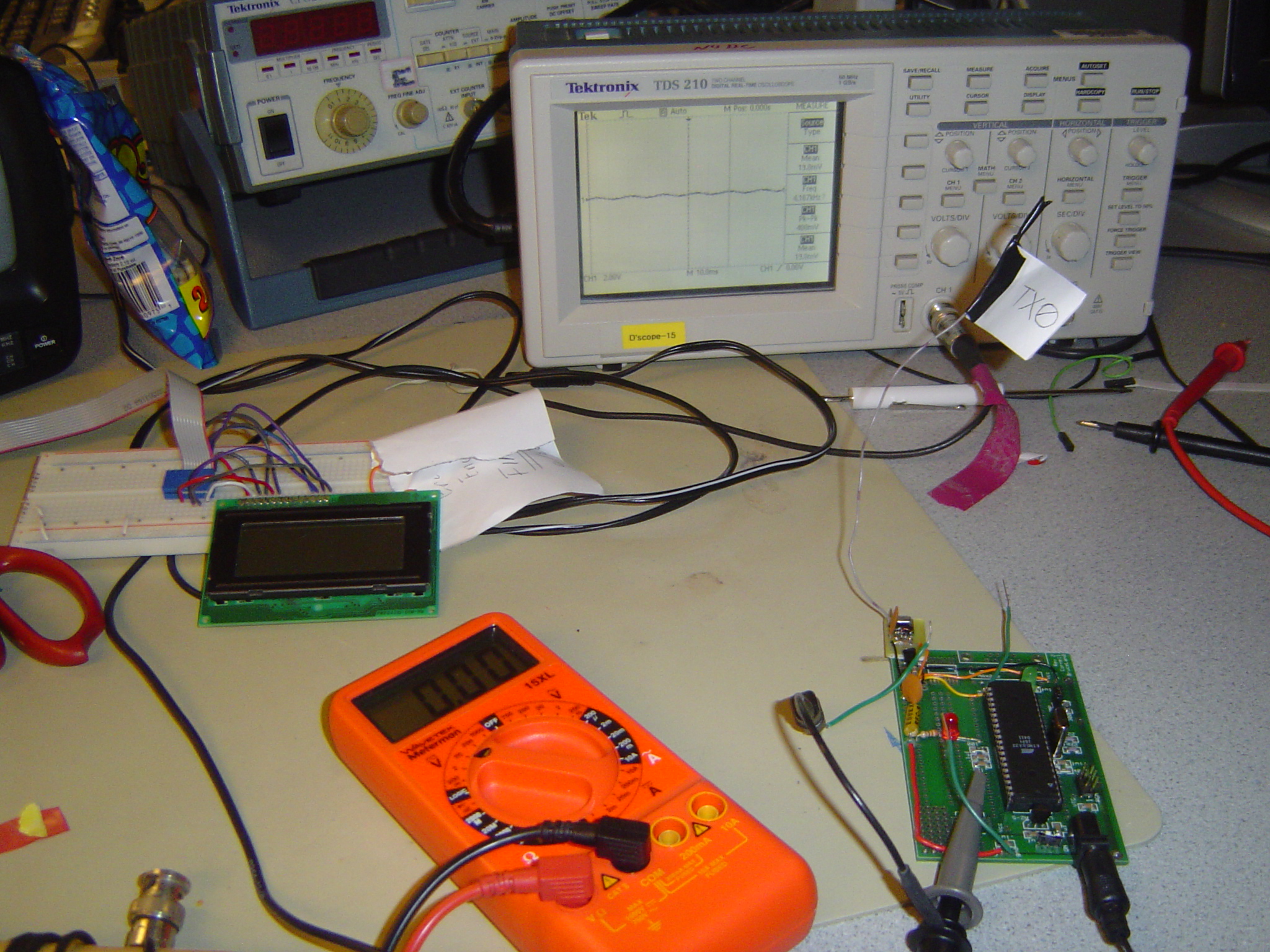
Testing the parts out on the oscilloscope

Eric Yu observing the oscilloscope
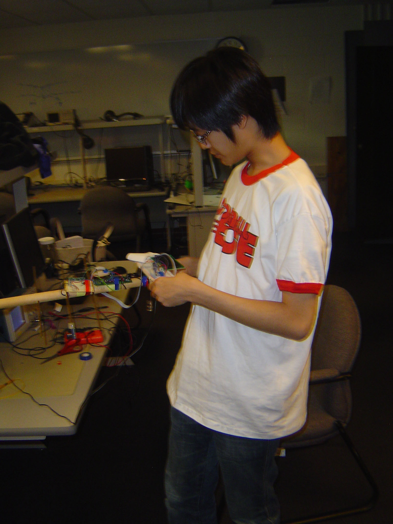
Eric Yu testing the project out
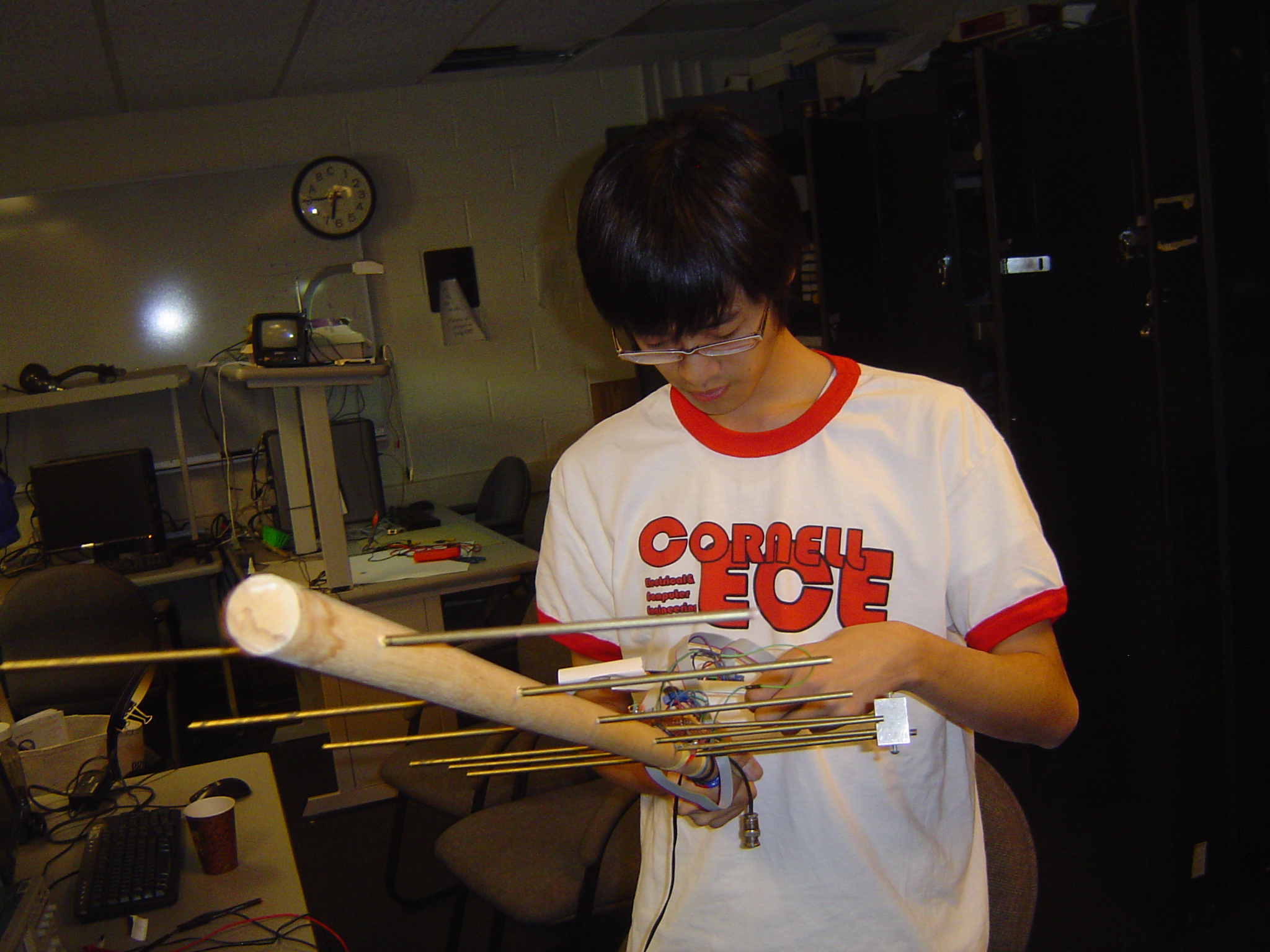
Eric Yu testing the project out (2)
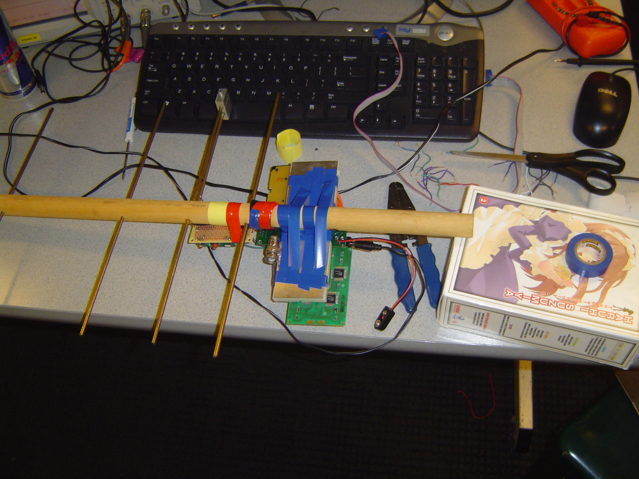
Further consolidating the structure of the project with tape

Further consolidating the project with tape (2)

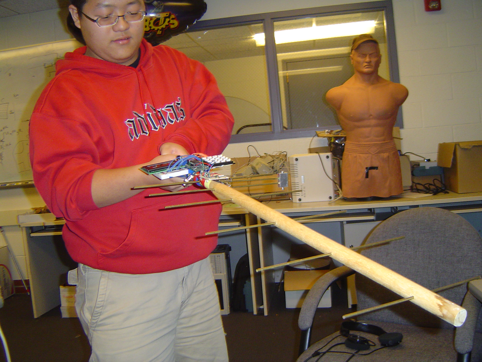
Eric Chen taking the project out for a test run

Appendix
Appendix 1: The Code
Transmitter code: tx.c
Receiver code: rx.c
Transceiver driver code: rxtx.c
Appendix 2: Schematics
High-level Design:
Transmitter:
![]()
Receiver:
Appendix 3: Parts List
Parts name |
Source |
Cost |
| ATMega32-16PU | Atmel (via Bruce Land) | $8 * 2 = $16 |
| Small solder board | Bruce Land | $1 * 2 = $2 |
| 9V Battery | Best Buy | $2 * 2 = $4 |
| Proto-board | Bruce Land | $5 * 2 = $10 |
| RCR-433 Receiver | Radiotronix (via Bruce Land) | $4 * 2 = $8 |
| RCT-433 Transmitter | Radiotronix (via Bruce Land) | $4 |
| LCD | Bruce Land | $ |
| 40-pin DIP | Bruce Land | $0.5 * 2 = $1 |
| Antenna | Borrowed from Bruce Land | $0 |
| Keypad | Bruce Land | $6 |
| Wire, capacitors, misc electronics | Bruce Land | $0 |
Total = $63
Appendix 4: Work Distribution
Eric Yu
Antenna (whip antenna only), receiver, and transmitter construction
Overall programming
Final report writing
Website construction
Eric Chin-Hung Chen
ATMega32 Protoboard construction (x2)
User interface programming
LCD display set-up
Final report writing
Diagram and schematic drawing
References
Books:
Antenna Book. Newington, CT: The ARRL, 2003.
Weisman, Carl. The Essential Guide to RF and Wireless. Uppder Saddle River, NJ: Prentice Hall, 2002.
Datasheet:
RCR-433-RP
RCT-433-AS
Code/designs borrowed from others:
Tytus Mak and Daniel DiBernardo “Touch Screen Controlled R/C Car”
Meghan Desai “WIRELESS TRANSMIT AND RECEIVE (WITxRx)“
Donn Kim & Antonio C. Dorset “Dual Control R/C Car”
Background sites/paper:
Antenna:
http://www.rfm.com/corp/appdata/antenna.pdf
http://www.skyscan.ca/Antennas.htm
RF:
http://www.access.gpo.gov/nara/cfr/waisidx_01/47cfr15_01.html
http://www.rfcafe.com/references/electrical/antenna_patterns.htm
Others:
http://www.nbb.cornell.edu/neurobio/land/PROJECTS/Protoboard476/index.html
http://instruct1.cit.cornell.edu/courses/ee476/labs/s2008/lab1.html
http://www.raibeam.com/wa7rai.html
http://www.ieee.org/web/membership/ethics/code_ethics.html
