|
Intelligent Wireless Pedometer |
Ping-Hong Lu |
|
Intelligent Wireless Pedometer |
Ping-Hong Lu |
Introduction | High Level Design | Hardware Design | Software Design | Result | Conclusion | Appendix
| Introduction |
For our ECE 476 Final Project, we have built an intelligent, wearable pedometer. This wireless pedometer can calculate many useful statistics such as the number of steps a user has taken, the distance and the speed the person has walked/run, as well as the number of calories the person has burned. This information is wirelessly transmitted to the base-station, and it is displayed on the PC in a useful manner. This project is in collaboration with the Ambumedics Project with John Belina.
Traditionally, pedometers only measure the number of steps a user has taken. Recently, more advanced pedometers include GPS units to calculate the distance a person has travelled, but using GPS substantially increase the cost of the product. Our project uses a low-cost accelerometer to determine the distance, speed, number of steps taken, and calories burned of a user instead.
| High Level Design |
The project will consist of two main components, the wearable sensor and the base-station. The wearable sensor includes an accelerometer, an Atmel Mega 644V microcontroller and an RF transceiver. The base-station will consist of an Atmel Mega 644V, RF transceiver, and MAX233 chip for RS-232 serial communication. The wearable sensor will take the raw data produced by the accelerometer and make determinations on the speed, distance, and number of steps the user has taken. The wearable component will send its interpreted data wirelessly to the base station for aggregating and displaying pertinent data to the user. The following is a high-level block diagram of the system we built.
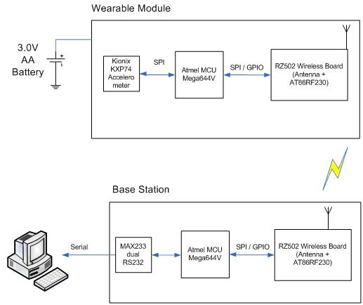
Figure 1 - High-level block diagram of the wireless pedometer system
The wearable module is powered from a 3V battery source with two AA batteries in series. The device is tied around the user's leg, with the accelerometer strapped on the top of the user's shoe. The calculations on step detection, distance, and speed are done on the wearable sensor, and the result is transmitted wirelessly to the base-station. The result is displayed on the PC through RS232 serial communication with MAX233. The following image shows the actual hardware used.
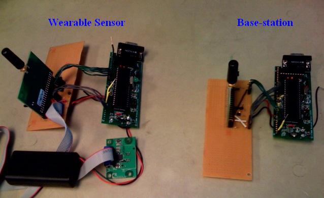
Figure 2: Image of the actual pedometer system
Although the wearable sensor seems bulky and impractical to wear, keep in mind that this is only a prototype. If all components are populated on a single PCB using small packages (DFN or BGA), the size can be significantly reduced. Unfortunately we do not have the budget to fabricate a PCB that costs thousands of dollars for a prototype spin :). For now, the most important aspect is to make the system work with the available resources given to us.
| Hardware Design |
Wearable Sensor | Base-station
The two major hardware components in this project are the wearable sensor module and the basestation, which are detailed below. A previous 476 project (Movement of Music) is used as a helpful reference for the hardware design.
The wearable sensor includes the accelerometer, AT Mega644V MCU and the RZ502 wireless module, as illustrated in the block diagram in Figure 1. The following image shows the wearable sensor and its various components.
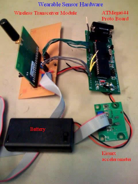
Figure 3: Wearable sensor hardware
Tri-Axis Accelerometer
The accelerometer we chose is KXP74 from Kionix. It is a ±2g tri-axis digital accelerometer. This is an ideal part for our application for the following reasons:
The accelerometer comes in a 5x5x1.2 mm DFN package only, which can make hand soldering fairly stressful. Luckily, Kionix provides free evaluation board (EVAL-74) with a standard 10-pin connector. The following shows the schematic of the evaluation board, and its connection to the AT Mega644V board.
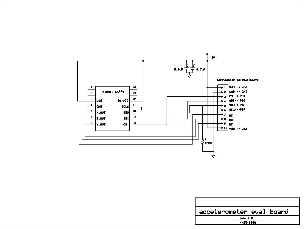
Figure 4 - Schematic of the KXP74 tri-axis accelerometer
Wireless Transceiver
We have based our wireless design on Andrew Godbehere’s and Nathan Ward’s previous 476 project, which uses Atmel’s 2.4GHz radio transceiver AT86RF230. This wireless chip has several advantages:
However, we wanted to avoid the troubles of hand soldering 32-QFN package. Luckily, the AT86RF230 chip also comes in an Atmel evaluation board (RZ502). Since this is a conjoint project with John Belina’s Amubumedics Project, we are able to borrow two extra RZ502 boards that Amubumedics Group previously owned. The following is the schematic for the RZ502 wireless transceiver board from Atmel’s application note.
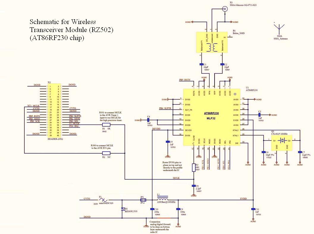
Figure 5 - Schematic for wireless transceiver Module (RZ502) from Atmel’s Application Notes
ATMega644V MCU board
The ATMega644V board is populated using Bruce’s Prototype Board for Atmel Mega32. We have used ATMega644V instead of ATMega32 because:
The following is the schematic of the ATMega644V MCU Prototype board.

Figure 6 - Schematic for ATMega644V prototype board on the wearable sensor
The accelerometer and the wireless transceiver is connected to the MCU through Port B using SPI for data transmission. Port C is used as GPIOs to command the transceiver. Please note that the schematic only shows the MCU connections to the accelerometer and the transceiver, external components for the MCU that are on Bruce’s prototype board are not shown. Please refer to Bruce’s Prototype Board webpage for that information.
We are using a 8MHz crystal on the Mega644V, instead of a 16MHz crystal usually found on the Mega32. This is because Mega644V can only run on 8MHz if it is in low-power mode running at 3V. For our pedometer application, detecting step information for a fast runner will require a maximum sampling rate on the order of hundreds of ms. As a result, operating the MCU at 8MHz is more than sufficient, and it is possible to make the speed tradeoff for lower power consumption.
The base-station is essentially the same as the wearable sensor, except that it does not require the connection of an accelerometer. The following image is the actual base-station hardware.

Figure 7 - Base-station hardware
Originally, the SDK500 with Mega32 is intended to use as the base-station for its simplicity. Nonetheless, the wireless transceiver RZ502 which is connected to the MCU through SPI can only run on 3V. This proposes the problem of maintaining separate power supplies for the SDK and the wireless transceiver. Moreover, using different voltage levels requires additional level shifting circuitry between SPI communications. As a result, we decided to build the base-station using the same hardware as the wearable sensor for consistency. The schematic for the base-station is depicted below.
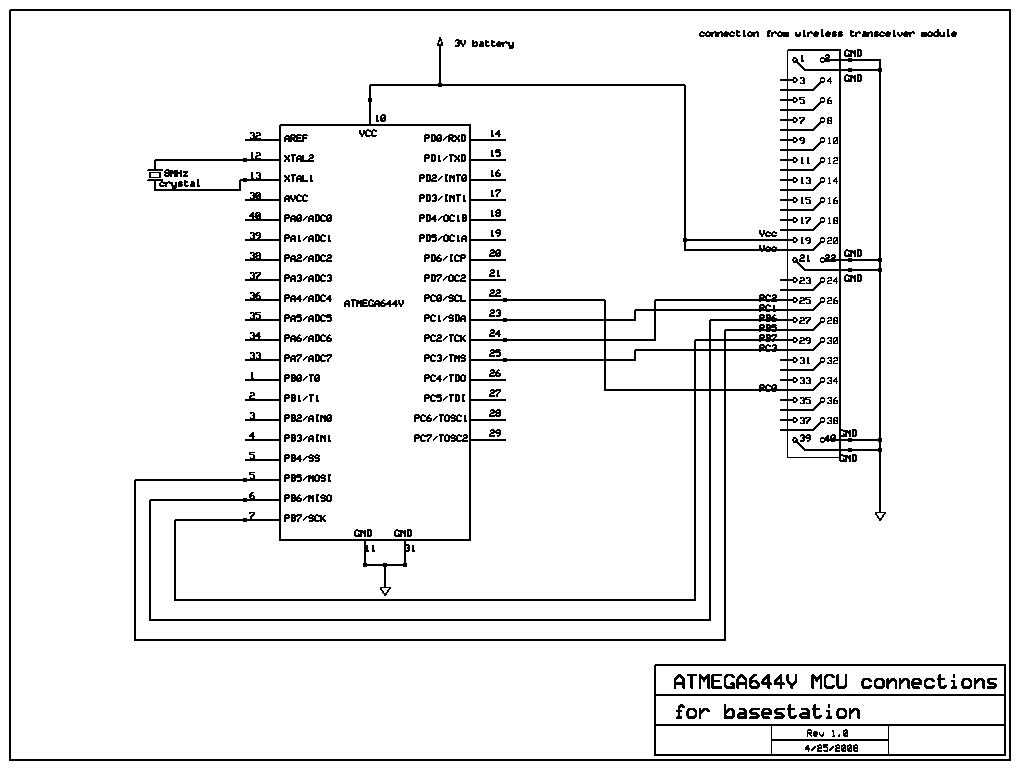
Figure 8 - Schematic for ATMega644V prototype board for the base station
Similarly to the wearable sensor, external components for the MCU that are on Bruce’s prototype board are not shown. Please refer to Bruce’s Prototype Board webpage for that information. The MAX233 chip is also populated on the prototype board for serial communication to the PC.
| Software Design |
Two Mega644V’s were used, each with its own code which was split into two separate CodeVisionAVR projects. One Mega644V, which was part of the wearable hardware, interpreted raw data from the Kionix KXP74 three-axis accelerometer and used the Atmel AT86RF230 transceiver to send information such as the distance the user has traveled or the user’s speed. This software is built upon code from "Movement of Music" 476 project for the RF transceiver and the accelerometer, which were libraries in header files. The other Mega644V was part of the base station hardware, and it received information from the wearable hardware as well as performing calculations for the amount of calories burned. In order to carry out this calculation, it prompts the user for their weight from a terminal emulation programmed via a serial port. The base station also utilized the Atmel AT86RF230 transceiver header file. All code was written in the C programming language through the CodeVisionAVR IDE.
Wearable Hardware’s Data Acquisition
The Mega644V on the wearable hardware polls the Kionix KXP74 accelerometer for information every 16 ms. All communication between the two devices are carried out over a SPI interface with the Mega644V acting as the master and the KXP74 acting as one of the two slave devices, the other being the RF transceiver. Each axis must be polled separately with a minimum of 40 μs in between polls to give enough time for each poll to complete. SPI initialization code written for a previous ECE 476 project by Andrew Godbehere and Nathan Ward was used upon start up to initialize the clock phase/polarity and to correctly set the operating modes of the accelerometer.
Step and Distance Calculation
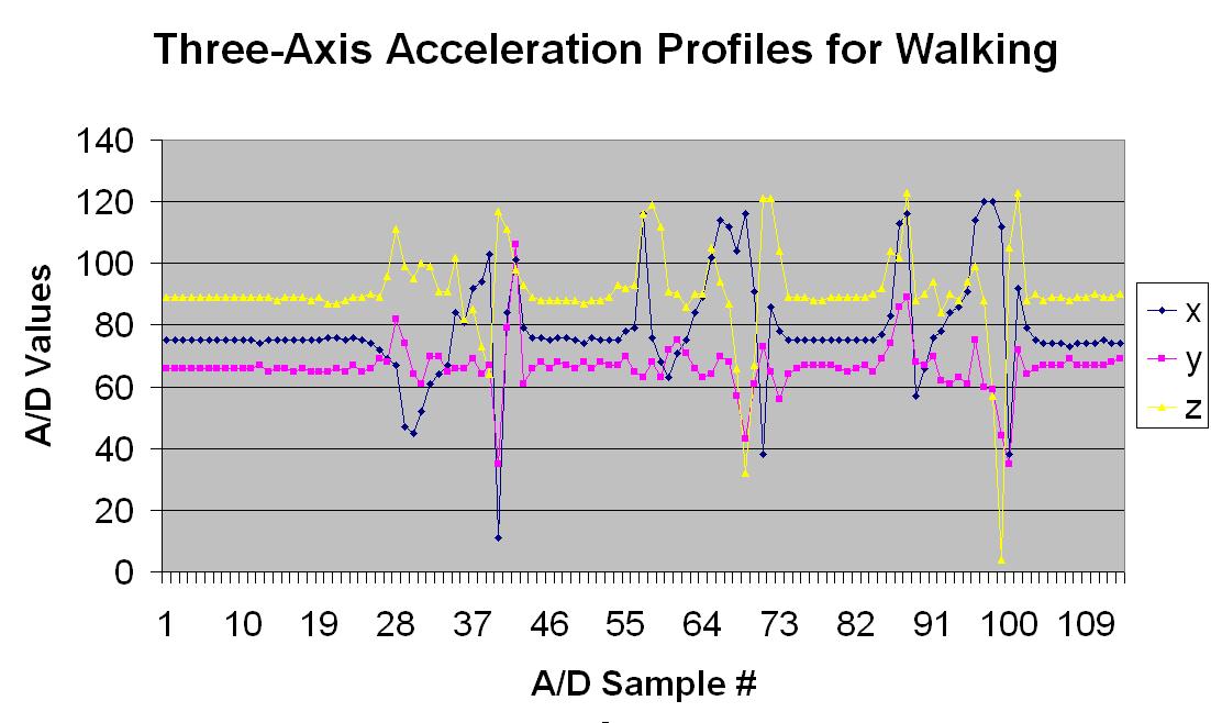
Figure 9: 3-axis acceleration profile when walking
It was noted that each distinct step was always characterized by two accelerations on the X-axis along with one steep deceleration in the Z-direction. This was used in coming up with the finite state machine depicted below.
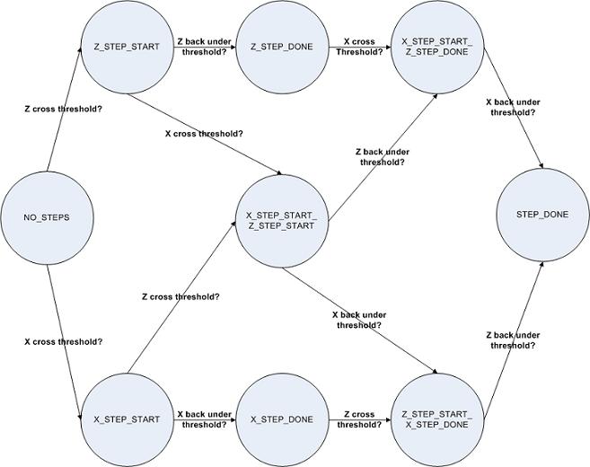
Figure 10: State machine for step detection
In addition to the detection of the steps, a distance calculation was also a part of the pedometer. To properly calculate the distance traveled, one needs to take into account the X and Z accelerations because the foot (and sensor) does not remain parallel to the ground during the entire step. To complicate matters, the faster one walks, the more different the foot positions are. This method of calculation is extremely complex which was not desirable for our simple 8-bit MCU controlled real-time embedded system, and so it was decided that a much simpler approach would be used. Our method consisted of simply using the X-direction’s acceleration readings to determine the distance traveled, as well as scaling that reading up whenever it was determined that the user was running instead of walking. The calculation for distance from a known velocity and time is integrating the velocity and evaluating the time interval in question, or in other words taking an integral. To approximate a good parabolic equation's integral, Simpsons's rule was used on every set of three samples, with the third sample of one data set being the first sample of the next data set. The method of differentiating walking versus running was by using a counter in between steps and depending on the count value, it could be determined how fast the user was moving. The exact values of the X-axis readings for 1 meter was calibrated by many trials of walking at a slow pace. In order to take into account physiological differences in users and the orientation of how the sensor sat on the user’s foot, a simple adaptive calibration was done upon start up where the initial default X value was recorded and all step detections as well as distance calculations were done when outside of that default position.
Simpson’s Rule
By finding the area under the curve of the accelerometer data in Figure 9, we can determine the distance the user has travelled. In order to perform this calculation accurately, Simpson’s Rule is used to improve our numerical approximation. Simpson’s Rule states that:
![]()
where f(x) is a signal such as: 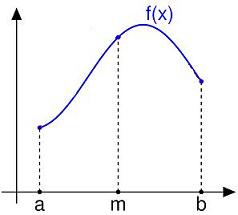
In our case, f(a) is the initial value of the axis acceleration, f((a+b)/2) is the middle value, and f(b) is the end value As a result, we need to take 3 samples of the acceleration information in order to perform such integration. The time interval between each sample is 16ms, hence our numerical integration becomes:
![]()
Wireless Link
The AT86RF230 transceiver is a slave SPI device on both Mega644V chips. The useful library exists in the aforementioned header file (at86rf230.h) that takes care of register initializations and transmit/receive functionality. A general SPI initialize function exists for the radio board, along with a clock setting API. There are separate functions to initialize the radio for transmit and receive, and a simple transmit-before-receive technique is used to ensure synchronization among the transmitter and receiver. This technique consists of the receiver module changing its settings as a transmitter, sending a “data request” message, and then turning itself back as a receiver and waiting 10ms for a response. If no response is received within 10ms, it will try the process again in the next running of the task. On the transmitter end, if the task has information to send, it will first change its settings to become a receiver and look for the “data request” message and then turns itself back into a transmitter. Only if it receives this message, does the module actually transmit RF data.
In addition to the SPI, there are some control lines that control the radio’s reset, transmit, and interrupt requests that indicate successful transmissions to the microcontroller. These are hardwired to PORTC.0-3 on each of the Mega644V’s.
While the communication protocol employed in the project is not 100% 802.15.4 compliant, it is a simpler subset, and with additional changes can become fully compliant with the 802.15.4 standard. Aside from the transmit-before-receive scheme, no other error checking is in place. As a result, if this project is running where other 2.4GHz devices are operating, it may receive garbage data and try to interpret them in the context of our project. However, we have not noticed significant performance degrade/malfunction when we tested our project in the 476 digital lab where Wi-Fi is present.
Details of the radio/Mega644V interface such as required delay times between radio state transitions are included in the AT86RF230 datasheet.
| Results |
The accuracy of the step detection as well as the distance calculations were within acceptable accuracy limits. The following table summarizes the experiments done for walking slowly, walking fast, and jogging. The overall accuracy for the number of steps and distance in each category are included in the table.
Table 1: Percentage error for different walking speeds
| Slow Walking (~2-3mph) |
Fast Walking (~4mph) |
Jogging |
|
| Percentage Error in distance | 2% | 2% | 4% |
| Percentage Error in step count | 7% | 10% | 14% |
The wireless communication drops a few frames, estimated to about 10% of all packets. This is the result of possible interference with other 2.4 GHz devices such as wi-fi. In addition, the communication protocol had no retry mechanism in place. Since our focus of the project is not on entirely based on wireless, we did not implement any detailed wireless stack. Information are transmitted and received with a simple handshaking acknowledgement. However, because the wearable sensor side is carrying out distance, step, and speed calculations, the missed packets do not affect the accuracy of the data shown to the user. In addition, the transmitter sends data so frequently and the user's movements are much slower than the 8 MHz CPU, the dropped frames are not visible to the user. The following table shows the accuracy of our wireless pedometer. Experiments are done on a 30-meter distance in the lab with 5 trials for each speed.
| Conclusion |
The pedometer performed well beyond our expectation. The dropped wireless packets did not affect the visible results to the user, who sees a continuous update of distance, steps, speed, and calories burned. The method of calculating distance by performing approximate intregals using Simpson's rule proved to be accurate within reason and was very consistent over countless trials. The same can be said for the step detecting state machine which is accurate within a ten steps over 60 meters. While encountering sporadic hardware problems throughout testing, the final product is well protected and secured safely ensuring no hardware malfunctions. In addition to accuracy, our project is compliant with regulations for transmitting wireless signals.
Future Works
This project was done as a proof-of-concept, but it is conceivable that with some additional work, this could be turned into a commercial product. The Atmel AT86RF230 comes in a smaller form factor as does many of the other parts used. While the Mega644V was ideal for this prototype because of its lower operating power than the Mega32, a different microcontroller all together would probably be a better fit for a commercial product because additional robustness needs to be added. For instance, being a 2.4GHz product, the communication protocol needs error checking from other interfering sources such as wireless router and cordless telephones, i.e. some level of checksum/retry mechanism needs to be added. The other major area of work would be to have a more complex step/distance detection that is able to handle all ranges of walking and running at different speeds. This would involve accounting for the different angles involved in the walking/running. Other additional work! should be put into packaging the product.
Standards
These are the standards that may apply to our project:
Ethical Consideration
Due to the wearable nature of this project, many ethical considerations were taken into account. First and foremost, the safety of the user and those around them are of greatest importance. To ensure protection for the user, layers of separation were used to isolate the user from both heat and electric current. However, if the product were to be commercialized, many more issues would have to be taken into consideration such as the packaging and the usability of the device, i.e. adjustable fit and non-interference with the user’s natural walking/running motions. As for dangers from emission, harmful emissions are dependent on the emission power, and 2.4GHz technology was designed to emit very little power. In comparison, a cellular telephone emits about two thousand times the power emission of a simple 2.4GHz device.
| Appendix |
Source Code
wearable sensor code
base-station code
wireless header
accelerometer header
Part List
Part |
Part Number |
Source |
Quantity |
Cost ($) |
Total |
ATMega644V |
ATMega644/V |
Atmel |
2 |
Spares from Andrew Godbehere |
0 |
Tri-Axis digital SPI Accelerometer |
KXP74 (eval-74 board) |
Kionix |
1 |
Sampled |
0 |
Wireless transceiver and Antenna Module |
RZ502 board (AT86RF230 chip) |
Atmel |
2 |
Previously owned in Ambumedics Project |
0 |
Bruce Land Prototype Board |
NA |
ECE 476 Lab |
2 |
$5 |
10 |
MAX233 Serial chip |
MAX233 |
MAXIM |
1 |
Sampled |
0 |
Solder Board |
|
ECE 476 Lab |
2 |
$2.50 |
5 |
RS232 connector |
|
ECE 476 Lab |
2 |
$1 |
2 |
Sip or header socket/plug |
|
ECE 476 Lab |
40 pin |
$0.05 |
2 |
DIP socket |
|
ECE 476 Lab |
4 |
$0.50 |
2 |
Various connectors and discrete components |
|
|
10 |
$0.50 |
5 |
Battery and battery holder |
Two AA 1.5V in series |
Electronic store |
1 |
$5 |
5 |
Enclosure for the wearable circuitry |
|
|
|
Free food box |
0 |
Velco for the enclosure |
|
|
|
$3 |
3 |
|
|
|
|
Total Sum |
$31 |
References and Acknowledgements
This project is built upon a past ECE 476 project (Movement to Music) by Andrew Godbehere and Nathan Ward. Additionally, Andrew Godbehere has provided tremendous amount of help to get us started on the project, as well as providing us with ATMega644V parts, and we are extremely grateful for his guidance.
Thank you to Bruce Land for his assistance and providing the supplies in the lab, and the TAs who kept the lab open late for us. Thank you to John Belina for supplying us with the wireless transceiver module and making this project possible. Thank you Kionix for generously providing accelerometer samples.
Tasks
While Andrew is more involved with the hardware and Ping is more involved with the software component, all aspects of this project are jointly developed.
| Misc. Images |
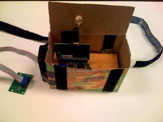
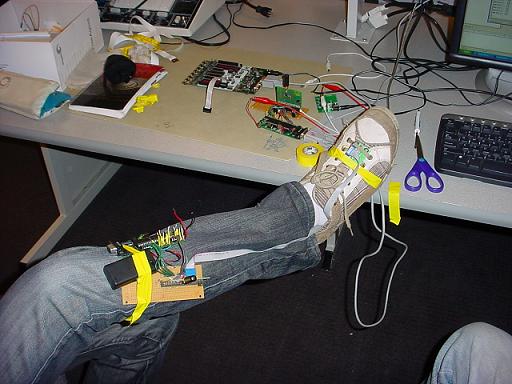
Wearable Sensor in our custom-made enclosure from a cardboard box
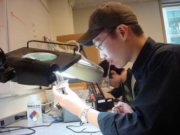
Trying to program the wearable sensor
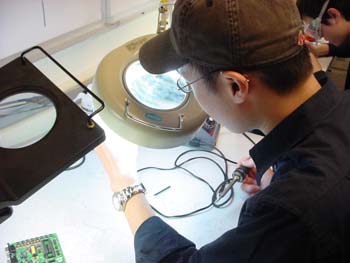
Ping and Andrew soldering
Ping hard at work
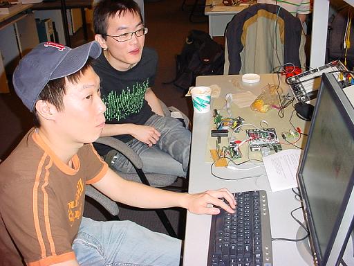
Ping and Andrew working hard, barely noticed someone's taking a picture
ECE 476
Cornell University