ECE 476 Final Project
SCHEME INTERPRETER
Hyunsik E Minh (hem24)
Jiho "Ray" Choi (jc646)
Introduction
The purpose of this project is to create a Scheme interpreter using C language and Mega32 microprocessor. Using limited resource and memory in the microprocessor, the interpreter should function and work for basic Scheme commands. The main target of the project is to use the memory of the microprocessor as fully as possible to make the interpreter perform major functions. Also, there will be limitation of the number of loops and memory that the interpreter could face memory shortage. In order to relieve the memory restraint to certain level, both FLASH and EEPROM have to be used.
High Level Design
- Rationale -
The idea of the project started from the pseudo code of Scheme interpreter using C++. For the final project of the microcontroller class, our group hoped to find a project that could maximize the use of memory and microcontroller. Also, from the project, we hope to experience intense C coding experiment and understanding of new language, Scheme. Creating a Scheme interpreter using C, running in Atmel Mega32 microcontroller chip challenged the group to write a extensive and complicated C code that could run and interpreted by Code Vision AVR and microcontroller while understanding the structure and functionality of Scheme language. Compared to most of the group where they would have hardware complexity and difficulty, even though we don’t have something tangible hardware other than Mega32 chip and STK500 board, this project will have software complexity and challenges.
It would be extremely hard to create an interpreter without a pseudo code, but with experience in the previous class, the pseudo code enabled our group to understand and finish the project. Thus, we have to give credit to the professor Kyu-Seok Shim (Seoul National University) for providing pseudo code and lecture notes on Scheme language and interpreter.
- High Level Overview -
The high level design of this project is mainly the interpreter code and tokenizer. As UART and computer keyboard inputs are used, part of the code is to read and write the data in and out. The serial communication between PC and MCU has been used and the code has been obtained from course material (provided by Prof. Bruce Land) and modified to satisfy the need of our project. The code for interpreter has been started from the scratch with the reference of pseudo code.
The first and probably one of the most important part of the project is to create a tokenizer that could identify the input and create a tokenized version of input so that it could be used by interpreting step. As interpretation total rely on the output of the tokenizer, it is extremely important to have a correct tokenizer and the function that could read and output next token. Detail structure and explanation of how tokenizer works will be discussed in the software design section.
The interpreter can be divided into many sub-parts: Preprocessing, Make-hash, Build node tree (Read) and Evaluation. Each step of interpretation will be discussed again in software section.
- Trade Off -
As there were many different software problems, errors, and issues arose while creating an interpreter, we spend all our effort and time to make the interpreter to function correctly. Thus, as trade-off, it was impossible for us to spare time to create possible hardware related to the project, such as external memory, LCD and keypads.
- Standards, Copyrights & Patents -
For Scheme language, there are official IEEE standard and and a de facto standard called the Revisedn Report on the Algorithmic Language Scheme, abbreviated as RnRS, where n is the number of revision. R5RS standard is the most widely implemented and R6RS has been ratified on August 28th, 2007 for next major revision. As regarding the intellectual property, the e-mail has been sent to get consent for using course material (lecture note, peudo code) to professor at Seoul National University.
Hardware Design
The hardware design of this project is simple. STK500 board with Atmel Mega32 microcontroller unit has been used with serial cable connecting PC and the STK500 board. In order to enable the UART, the jumper has to be connecting PORT D pin 0 and pin 1 to the RS232-spare header. Also set up the termial to 9600 baud, no parity, one stop bit, and no flow control. There is no other hardware requirement to run the interpreter.
Software Design
This project is very programming-intense that our group spent most of our time programming and fixing the code. The trickiest part was fitting the data structure into the limited memory and preprocessing the command and creating some functions such as GetNextToken. Also, the pseudo code provided by Prof. Kyu-Seok Shim in Seoul National University has been an important source for our interpreter.
- Data Structure -
There are two main data structures which are the node tree and the hash table.
Initially, the interpreter allocates a large number of nodes consisting three pointers, left child, right child and next. Left child and right child are for pointing other nodes or symbols, and next is for the nodes waiting at the free list. After receiving input commands, node trees would be constructed to store arrays and user defined functions. Unused nodes would wait for further commands at the free list.
When a new command comes, the interpreter stores new symbols into the hash table. The hash table is efficient in that the access time is much shorter than the regular table with search algorithms. The hash function would be specified carefully to minimize collisions. To distinguish nodes from symbols, we would use positive indices for node ids, and negative indices for the hash table. Each entry of the hash table has its symbol and a link of value. The variables would be linked to the index of the hash table or the root node of the array, and user defined functions would be linked to the root node of the node tree where the function has defined.
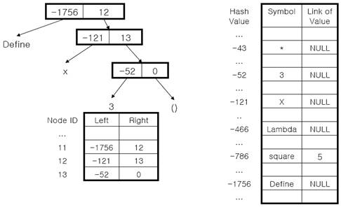
Figure 1. Tree Structure and Hash Table
- Limited Memory -
In order to perform as an interpreter we need to have a hash table and node tree that could store the value and also evaluate. However, there is limited memory within the Mega32 chip (2048 bytes for SRAM). Because of memory shortage, the program frequently showed errors and did not function correctly. Also, there could be limited number of lines and complexity of the function that could be used due to memory shortage. Specifically, the data stack size was too small, so there was the limit to the number of recursive function calls. In order to release such restriction on memory, we put the entire node tree and the hash table into EEPROM which has 1024 bytes of memory. This enabled us to increase the data stack size to the reasonable size that the program works for basic functionalities.
- Tokenizer -
The tokenizer is the most basic and important part of the project. It divides the command into tokens, and returns the next token every time it is called. Tokens could be divided by a space, parenthesis, and a quotation mark. The tokenizer searches the command for those three characters, and returns a string between two of them. Parenthesis and a quotation mark are also tokens, so it returns them as a token, too.
- Preprocessing -
The first step of creating an interpreter is to get the input string and preprocess it. We need to make sure to differentiate different inputs and put it into a readable and interpretable form. In order to enable serial communication, the code used in Lab 3 has been used. We modified the code to meet the need of our project. This source code for serial communication has been provided by Prof. Bruce Land. After receiving the command, the interpreter starts preprocessing. It converts the command into the standard format. The standard format includes using the quote function instead of a quotation mark for an array and using the lambda format for the user defined functions. Also, after preprocessing, the command would have only one space between every two tokens.
For example, if the command is (define (square x) (* x x)), after preprocessing it would be ( define square ( lambda ( x ) ( * x x ) ) ).
- Make Hash -
This function reads the command after preprocessing, and insert new symbols to the hash table.
- Node Tree Construction -
It is done by the function Read. The scheme command is relatively simpler than other programming languages. The basic form is (func arg1 arg2 … argN) where each argument could be the other command. The left child of the node points to each token, and the right child of the node points to the next node.
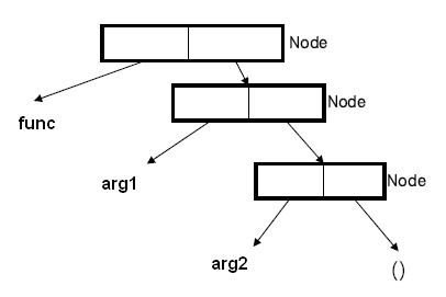
Figure 2. The Basic Form of The Node Tree
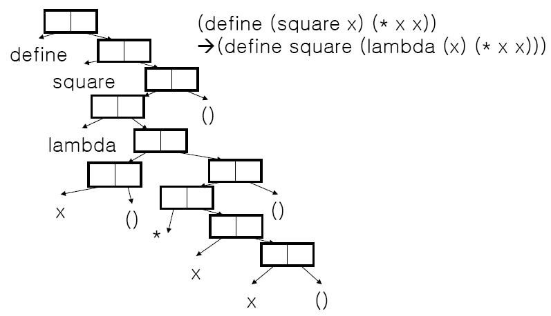
Figure 3. The Example of The Node Tree
- Evaluation -
The left child of the root node would be the symbol of "func". It evaluates arguments by recursively calling the function Eval, and then finally evaluate the command.
Function |
Behavior |
+ |
returns arg1 + arg2 |
- |
returns arg1 - arg2 |
* |
returns arg1 * arg2 |
< |
if arg1 > arg2, returns #t, else #f |
> |
if arg1 < arg2, returns #t, else #f |
= |
if arg1 = arg2, returns #t, else #f |
eq? |
if arg1 and arg2 are pointing to the same object, returns #t, else #f |
equal? |
if arg1 and arg2 are the arrays consisting of the same elements, returns #t, else #f |
number? |
if arg1 is a number, returns #t, else #f |
symbol? |
if arg1 is not a number, returns #t, else #f |
quote |
returns arg1 which would be an array or a symbol |
car |
returns the first element of arg1 which is an array |
cdr |
returns the array after removing the first element from arg1 which is an array |
cons |
prepends arg1 to arg2 which is an array, and returns arg2 |
display |
returns the value of arg1 |
define |
set a pointer of arg1 to arg2 |
cond |
condition statement |
lambda |
returns itself which would indicate it is a user-defined function |
- User Defined Function -
If we define a function using some symbols as its argument, we need to set the pointers of those symbols to the arguments we are using every time we use the function. However, the symbol could already point to something, and we could not just change the pointer of the symbol. Therefore, we need to store the pointers before we evaluate the user defined functions, change the pointers to the arguments, evaluate the command, and finally reset the pointers. We have done this job by using stack of the pointers.
As written in proposal, our initial goal was to create hardware that could display and input to the interpreter using external LCD and keypad (or keyboard). Also, due to memory shortage issue, we also thought of using external SRAM to solve the problem. Along with difficulty of using external SRAM, we decided to maximize the use of memory within in the MCU chip rather than putting the external memory. That is, we want to find how far we could reach only using a single Mega32 microcontroller unit by assigning node tree and hash table to EEPROM rather than SRAM. Because of the memory problem and many bugs and errors arose, we could not have a chance to create external display and keypad but simply used UART and serial communication.
Results
By the end of the project, we manage to successfully create a Scheme interpreter using Mega32 microcontroller unit. Basic functionality described in the software section worked fine without problem. For the time when “stack overflow error” shows up, the user has to reset the program to reuse it. Also, it is possible to use a function up to 11 times recursively (for example Fibonacci function will work up to 11). If it goes over this limit, the program will reset and do not return any value. This is because we have limited data stack size in the sram memory. With external or additional memory, this interpreter will work further. Also, there is limitation on the number of commands that you can execute for each reset time, which is also due to limited data stack size, hash table size and node tree size. As mentioned above, both hash table and node tree are in eeprom (used 98.8% of eeprom) to maximize the data stack size available. Also, the array that ha!
s default characters (25 components) is pushed in to flash memory. The data stack size has been set to 1000 Bytes. To verify that our interpreter is functioning correctly, we tried various commands and syntaxes. It is true that we didn’t test the interpreter for entire possible cases.
- Example Tesing Cases -
- Simple arithmatics
ex. (+ 3 4) returns 7, (* 4 5) returns 20. - Array functions
ex. (car '(1 2 3)) returns 1, (cdr '(1 2 3)) returns ( 2 3 ). - Condition operations
ex. (cond ((= 1 2) 0) (else 1)) returns 1
ex. (number? 5) returns #t. - Finding the length of the array
(define (l x) (cond ((null? x) 0) (else (+ (l (cdr x)) 1))))
ex. (l '(1 2 3)) returns 3. - Factorial function
(define (f x) (cond ((= x 0) 1) (else (* (f (- x 1)) x))))
ex. (f 5) returns 120.
As the project is software-centered, there is no safety issue or interference with other people’s designs. The only hardware problem could be the misconnecting serial communication ports or other basic STK500 settings. Any person who knows Scheme language could use this interpreter. To use this program, the person has to have access to serial communication between STK500 board and PC.
Conclusions
Our group is pleased to complete the targeted programming and create a usable Scheme interpreter. As interpreter itself, the result met the expectation of our initial goal. The interpreter was usable to do basic functionalities within the limit of memory. The memory issue was a big concern at the beginning of the project that there was a possibility that we could not run an interpreter using Mega32 microcontroller unit. However, it came out that even though it is limited, the functionality that we wanted to achieve could be performed without using any external memory. It was hard to control the different memory sizes to satisfy our needs but we are please to have an interpreter within a single MCU.
One part we will do differently for next time is to fasten the project and to try to build some external hardware input and output (such as keyboard and LCD) so that it could be actually portable. Our group believed that rather than using external memory, it was more valuable to challenge to handle limited memory. Also, with more time, we could try displaying different errors and do garbage collection to reduce the waste on the use of nodes.
As the interpreter gives a correct result according to the Scheme syntaxes, we strongly believe that it meets the standard for Scheme language. It is true that we don’t have entire list of commands available in Scheme language, but we have sufficient commands and correct interpretation of Scheme language to use.
- Intellectual property & Legal consideration -
As mentioned in previous section, we used the code provided by Prof. Bruce Land for serial communication between MCU and PC. The code has been taken from the link in Lab3 and modified to meet the need of our project. Also, the important reference that we used throughout the project is the pseudo code from Prof. Kyu-Seok Shim in Seoul National University. Our group has produced the interpreter code that we don’t think there is any intellectual property issue. Also, as long as we followed the standard of using Scheme language, we will not have any legal consideration on this project.
- IEEE Code of Ethics -
We believe our project is consistent with all the Code of Ethics provided by IEEE. All the code of ethics have been reviewed that we don’t violate any of them. As the project consist of simple hardware setting that has been used throughout the course, we don’t believe there is any environmental issue. For programming chip and serial communication between PC and MCU, STK500 board and necessary wiring has been used for our project. There was no other possible source of safety problem that could arise from our project. Also, as we are creating an interpreter of Scheme language using C, we tried to follow the standard for Scheme language so that we don’t violate any rule or create a conflict. Our group is willing to provide the code and the sources and to accept any criticism or error to fix and correct. Any person could be able to use our code or any documentation created by our group. We tried all effort to be honest, safe and understand the possible !
hazard or any issue that could come across. Again, the project and the group stayed within the boundary of Code of Ethics throughout the project. As most of the codes were produced by the group, as we used some codes and pseudo-code provided by other people, we tried to mention and credit the people who have contributed to our project.
- Future work -
The possible future work on the project will be extending the possible command list of the interpreter and putting external memory to allow for better hardware stack size, node tree size and hash table size. In addition, it would be possible to create better test bench to fully test the interpreter.
Appendix
A. Commented Programming List [Link]
B. Pseudo Code for the project [Link]
C. Cost Detail
Part |
Quantity |
Price |
STK500 Board |
1 |
$15 |
Atmel Mega32 |
1 |
$8 |
STK500 Power Supply |
1 |
Free |
USB to Serial Cable |
1 |
Free |
Serial Cable |
1 |
Free |
2 pin Flat Jumper Cable |
1 |
$1 |
Total |
|
$24 |
D. Tasks done by each member
As the project was software-oriented, both of our group members worked on coding, testing, and debugging the project. As there are many functions that could be tested separately and even without microcontroller, different functions have assigned to each member. At the beginning of the project, Hyunsik Minh was in charge of making sure the serial communication works correctly while Jiho Choi created basic Hash table and structure that will be used. It is hard to exactly say a person worked at a certain function as most of the time we worked together to reduce the possible error in coding. With experience in creating interpreter, Jiho did many part of coding itself while Hyunsik performed testing and debugging the code.
E. Reference
a. DataSheet
- Mega32 [Link]
b. Code/Design from other source